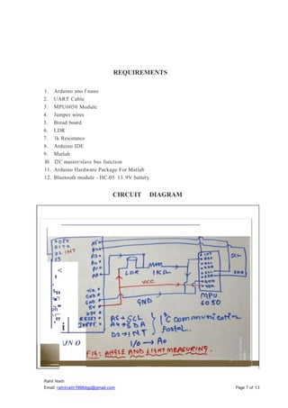
This project utilizes an Arduino Uno, LDR, and MPU6050 to measure the angle at which light intensity is maximized. By integrating data from the MPU6050's gyroscope and accelerometer with LDR voltage readings, the project aims to optimize lighting conditions for applications like solar panels. The findings indicate that the measurements of tilt angle against actual and theoretical values correlate closely, demonstrating the effectiveness of using a 3-axis accelerometer alongside an LDR.

![Rahit Nath
Email: rahitnath1998dgp@gmail.com Page 4 of 13
THEORY
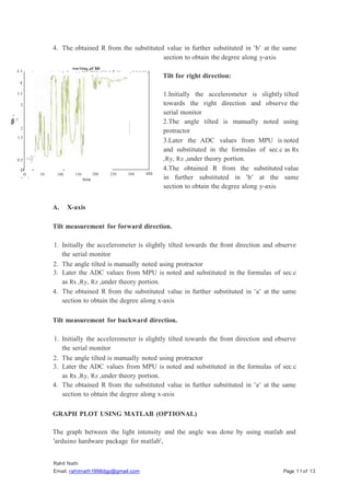
MPU6050 (ADXL335- 3-axis)
MPU6050 has an integrated 3-axis MEMS (Micro Electrical Mechanical Systems)
accelerometer and 3-axis MEMS gyroscope. The MPU 6050 is a 6 DOF (Degree of
Freedom) or a 6-axis IMU (Inertia Measurement Unit) sensor i.e. it will give 6 values
in output. Three values from accelerometer and three from gyroscope. This sensor
uses 12C protocol for communication.
Accelerometer is an electromechanical device provides the information of force acting
on or experienced by the object. Once the acceleration of the object is obtained,
successive integral computation can be used to calculate the velocity and distance
covered by the object. The rate of change of velocity gives the acceleration which can
be interpreted as the tilt angle.
The basic and important application of accelerometer is tilt measurement, tilt is the
static measurement where the gravity of the acceleration is measured and this
measurement employed in positioning, aliasing, leveling and navigation.
One of the general method of sensing tilt angle is to integrate the output of gyroscope.
A. Measuring tilt using one axis
As in the case of a dual axis accelerometer(xy) is fixed and perpendicular to gravity,
the tilt algorithm is restricted to one axis of sensitivity. The accelerometer is tilted
along x-axis and y-axis remains at Og output during the full form rotation of y-axis If
x-axis is used to analyze the tilted angle of the accelerometer then:
VoFF = VoUTx+ S *SIN0
[Where,
VoFF = offset voltage, VoUTx = voltage output from x=axis, s= sensitivity of the
accelerometer. And 0= the tilt angle.] 0= sin inv((VoFr VoUTx)/s)](https://image.slidesharecdn.com/lightintensityincidentanglemeasurement-230827141201-3185f957/85/Light-intensity-incident-angle-measurement-pptx-4-320.jpg)
![Rahit Nath
Email: rahitnath1998dgp@gmail.com Page 6 of 13
Rx = [((Vx
Ry = [((Vy
Rz = [((Vz
* Vref
* Vref
* Vref
)/2n -l) - Vzero] / Vsensitivity
)/2n -l) - Vzero] / Vsensitivity
)/2n -1) - Vzero] / Vsensitivity
R = sqrt(Rx2
+ Ry2
+ Rz2
+)
A= cos inv (Rx/R)
B= cos inv (Ry/R)
C== cos inv (Rz/R)
The value of VzERO, Yref, VsEN
S
ITNITY. Is measured
MPU6050.
from the data sheet of the
LDR
LDR stands fro light dependent resistor.
The working principle of an LDR is photo conductivity, that is nothing but an optical
phenomenon.When the light is absorbed by the material then the conductivity of the
material reduces. When the light falls on the LDR, then the electrons in the valence
band of the material are eager to the conduction band. But, the photons in the incident
light must have energy superior than the band gap of the material to make the
electrons jump from one band to another band (valance to conduction).
Hence, when light having ample energy, more electrons are excited to the conduction
band which grades in a large number of charge carriers. When the effect of this
process and the flow of current starts flowing more, the resistance of the device
decreases.](https://image.slidesharecdn.com/lightintensityincidentanglemeasurement-230827141201-3185f957/85/Light-intensity-incident-angle-measurement-pptx-6-320.jpg)