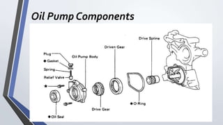
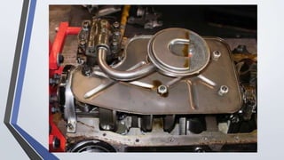
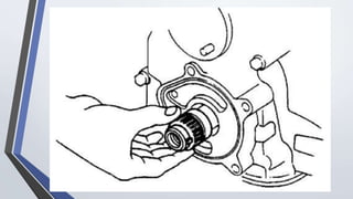
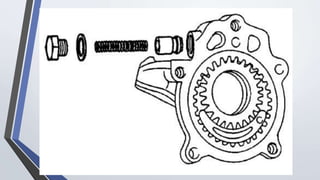
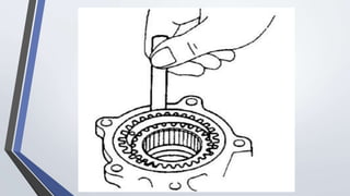
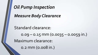
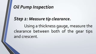
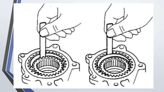
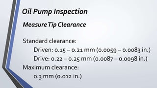
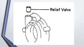
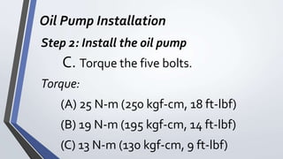
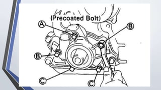
TOYOZU TECHNICAL SCHOOL
FOUNDATION, INC.
ATS NC II TRAINING SESSION
Batch 2021
OPENING PRAYER
Lord, help us in our online studies today. Give us
concentration so that may we listen, understand,
learn and have peaceful mind and may we always
remember that god is always with us
Good
Morning!
TTSFI ATS NC IITrainees
LESSON:
Check andTest Oil Pump Assembly
ATS NC IITraining Session
Objectives:
 Perform the proper procedure in checking
testing oil pump assembly.
LESSON:
Check andTest Oil Pump Assembly
INTRODUCTION
The oil pump is the heart of the
engine which it pumps vital lubricant and
supplies pressure to every moving part. The
pump is required to provide 3 to 6 gallons
of oil per minute while also maintaining
system pressure.
INTRODUCTION
Most oil pumps are driven off the
camshaft or distributor shaft. The pump
itself typically consists of two gears in a
close-fit housing. When the gear teeth
come out of mesh, they leave a space,
which is filled by oil drawn through the
pump inlet.
INTRODUCTION
Oil then travels to the space between
the gear teeth, where is it forced through
the teeth into an oil passage, creating
pressure.
INTRODUCTION
If your oil pump isn’t working
properly, it won’t be long until your engine
becomes an oversized paperweight. A
failed pump can lead to low oil pressure,
lack of lubrication, and eventual engine
failure.
Oil Pump Components
Procedure
in
Oil Pump Removal
Oil Pump Removal
TAKE NOTE:
When repairing the oil pump, the oil
pan strainer should be removed and
cleaned.
Oil Pump Removal
Step 1: Remove the oil pan.
Oil Pump Removal
Step 2: Remove the oil strainer.
Remove the four bolts holding the oil
strainer
Oil Pump Removal
Step 3: Remove the drive belts
Oil Pump Removal
Step 4: Remove the crankshaft pulley
Oil Pump Removal
Step 5: Remove the A/C compressor and
bracket
Oil Pump Removal
Step 6: Remove the oil pump assembly
A. Loosen the oil pump relief valve
plug.
Oil Pump Removal
Step 6: Remove the oil pump assembly
B. Remove the five bolts, the oil pump
assembly and o-ring.
Oil Pump Removal
Step 7: Remove the oil pump drive spline
TAKE NOTE:
If the oil pump drive spline cannot be
removed by hand, use gear puller to
remove the pump drive spline and
crankshaft together.
Procedure
in
Oil Pump
Disassembly
Oil Pump Disassembly
Step 1: Remove the relief valve.
Unscrew the relief valve plug and
gasket and remove the spring and the relief
valve.
Oil Pump Disassembly
Step 2: Remove the driven and drive
gears.
Procedure
in
Oil Pump
Inspection
Oil Pump Inspection
Step 1: Measure body clearance.
Using a thickness gauge, measure the
clearance between the driven gear and
body.
Oil Pump Inspection
Measure Body Clearance
Standard clearance:
0.09 – 0.15 mm (0.0035 – 0.0059 in.)
Maximum clearance:
0.2 mm (0.008 in.)
Oil Pump Inspection
TAKE NOTE:
If the clearance is greater than
maximum, replace the gear and/or body.
Oil Pump Inspection
Step 2: Measure tip clearance.
Using a thickness gauge, measure the
clearance between both of the gear tips
and crescent.
Oil Pump Inspection
MeasureTip Clearance
Standard clearance:
Driven: 0.15 – 0.21 mm (0.0059 – 0.0083 in.)
Drive: 0.22 – 0.25 mm (0.0087 – 0.0098 in.)
Maximum clearance:
0.3 mm (0.012 in.)
Oil Pump Inspection
TAKE NOTE:
If the clearance is greater than
maximum, replace the gear and/or body.
Oil Pump Inspection
Step 3: Measure side clearance.
Using a thickness gauge and flat
block, measure the side clearance as
shown.
Oil Pump Inspection
Measure Side Clearance
Standard clearance:
0.03 – 0.09 mm (0.0012 – 0.0035 in.)
Maximum clearance:
0.15 mm (0.006 in.)
Oil Pump Inspection
TAKE NOTE:
If the clearance is greater than
maximum, replace the gear and/or body.
Procedure
in
Pressure Regulator
Inspection
Pressure Regulator Inspection
Step 1:
Coat the valve piston with engine oil
and check that it falls smoothly into the
valve hole by its own weight.
Pressure Regulator Inspection
TAKE NOTE:
If the valve does not fall smoothly,
replace the valve and/or oil pump
assembly.
Procedure
in
Front Oil Seal
Replacement
Front Oil Seal Replacement
Step 1: Remove the oil seal
A. Remove the drive and driven gears.
B. Using a screwdriver, remove the oil
seal.
Front Oil Seal Replacement
Step 2: Install oil seal
A. Apply multi-purpose grease to a
new oil seal lip.
B. Install the new oil seal.
Procedure
in
Pressure Regulator
Assembly
Pressure Regulator Assembly
Step 1: Install the oil pressure regulator
A. Install the relief valve and valve
spring in the body and screw on the
relief valve plug with a new gasket.
B. Insert the drive and driven gears
into the pump body.
Procedure
in
Oil Pump
Installation
Oil Pump Installation
Step 1: Install the oil pump drive spline
and o-ring
A. Slide the pump drive spline onto
the crankshaft.
B. Place the o-ring into the groove.
Oil Pump Installation
TAKE NOTE:
If the oil pump drive cannot be
installed by hand. Use puller.
Oil Pump Installation
Step 2: Install the oil pump
A. Clean the threads of the upper bolt
and timing chain cover bolt hole of
any sealer, oil or foreign particles.
Remove any oil with gasoline fuel.
Oil Pump Installation
Step 2: Install the oil pump
B. Apply sealant to 2 or 3 threads of
the bolt end.
Oil Pump Installation
TAKE NOTE:
This adhesive will not harden while
exposed to air. It will act as a sealant or
binding agent only when applied to
threads, etc and air is cut off.
Oil Pump Installation
Step 2: Install the oil pump
C. Torque the five bolts.
Torque:
(A) 25 N-m (250 kgf-cm, 18 ft-lbf)
(B) 19 N-m (195 kgf-cm, 14 ft-lbf)
(C) 13 N-m (130 kgf-cm, 9 ft-lbf)
Oil Pump Installation
Step 2: Install the oil pump
D.Torque the relief valve plug
Torque:
37 N-m (375 kgf-cm, 9 ft-lbf)
Oil Pump Installation
Step 3: Install crankshaft pulley
Oil Pump Installation
Step 4: Install and adjust drive belt
Oil Pump Installation
Step 5: Install oil strainer
Oil Pump Installation
Step 6: Install oil pan.
Done……
Let’s Have
an Open
Forum
THANK
YOU!!!

Lesson - Check and Test Oil Pump Assembly.pptx