Download as PDF, PPTX


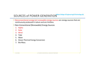
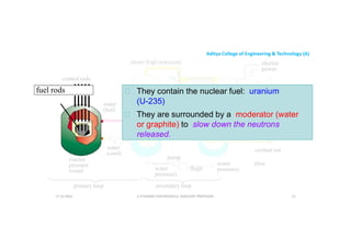
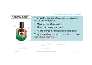
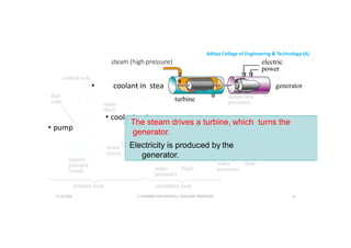
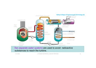
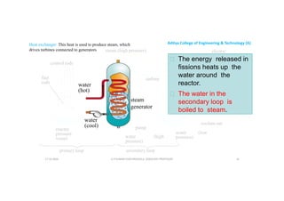
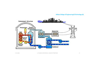
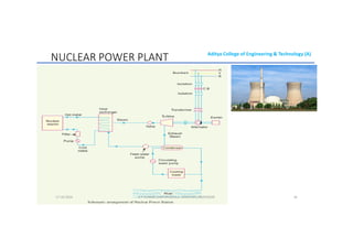
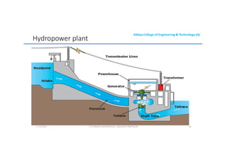
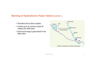
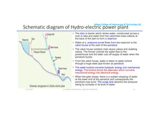
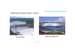


The document provides an overview of energy resources focusing on conventional and non-conventional power generation systems, including nuclear, hydel, solar, and wind power. It discusses the operation, construction, advantages, and disadvantages of these systems, highlighting key aspects such as energy conversion, safety measures, and environmental impact. Additionally, it explains the components and functioning of nuclear power plants and hydropower plants in detail.