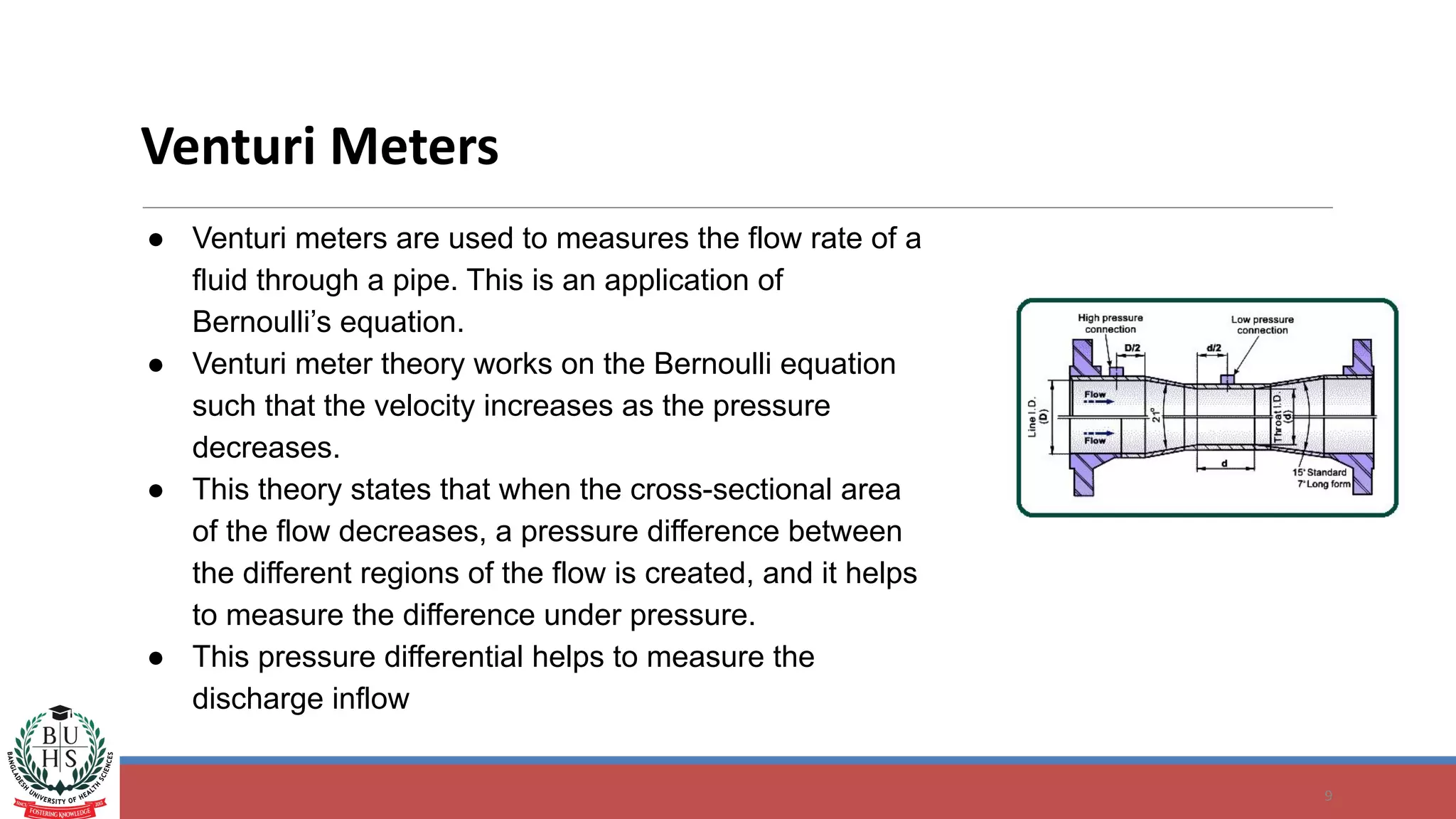
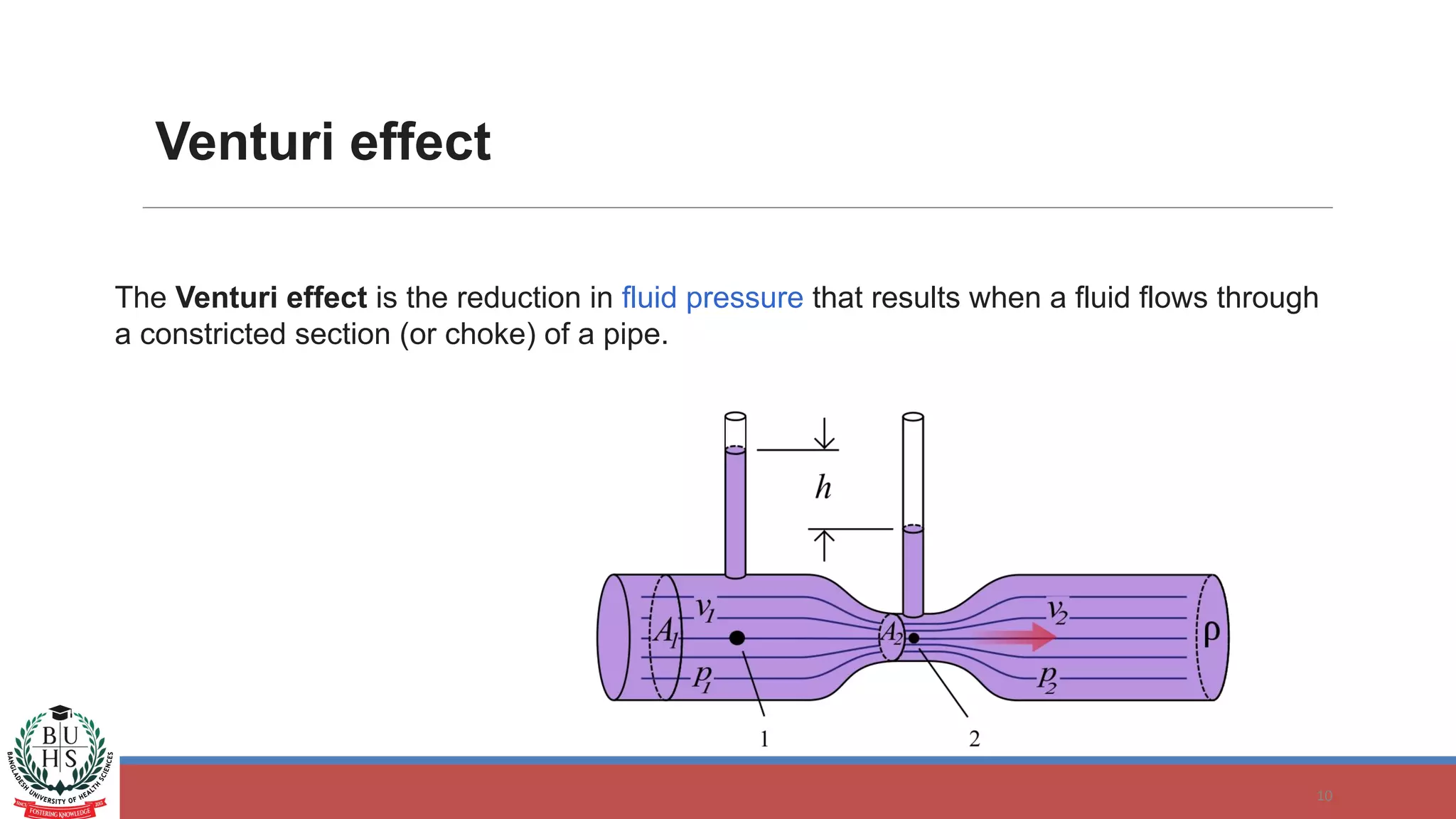
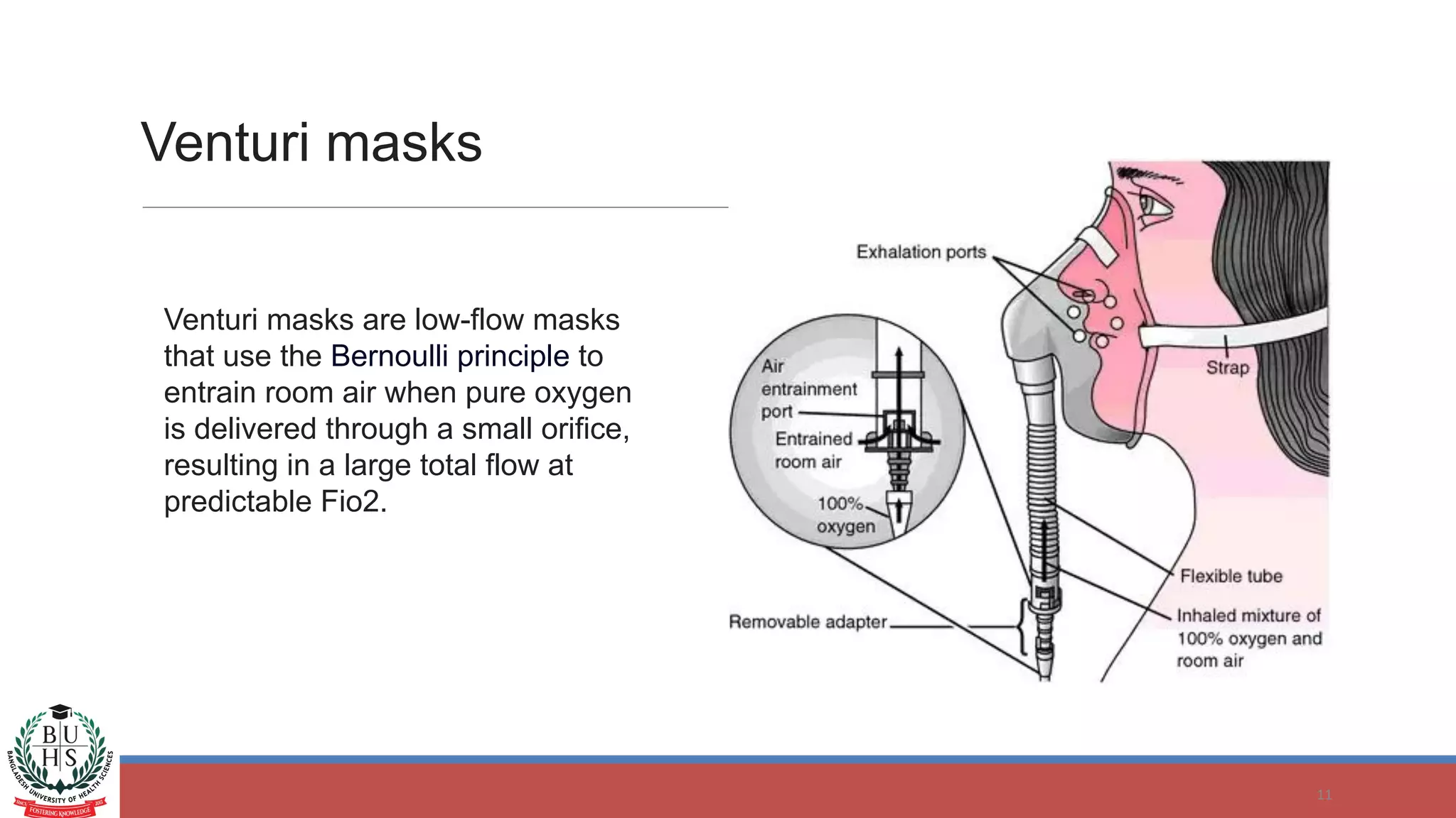
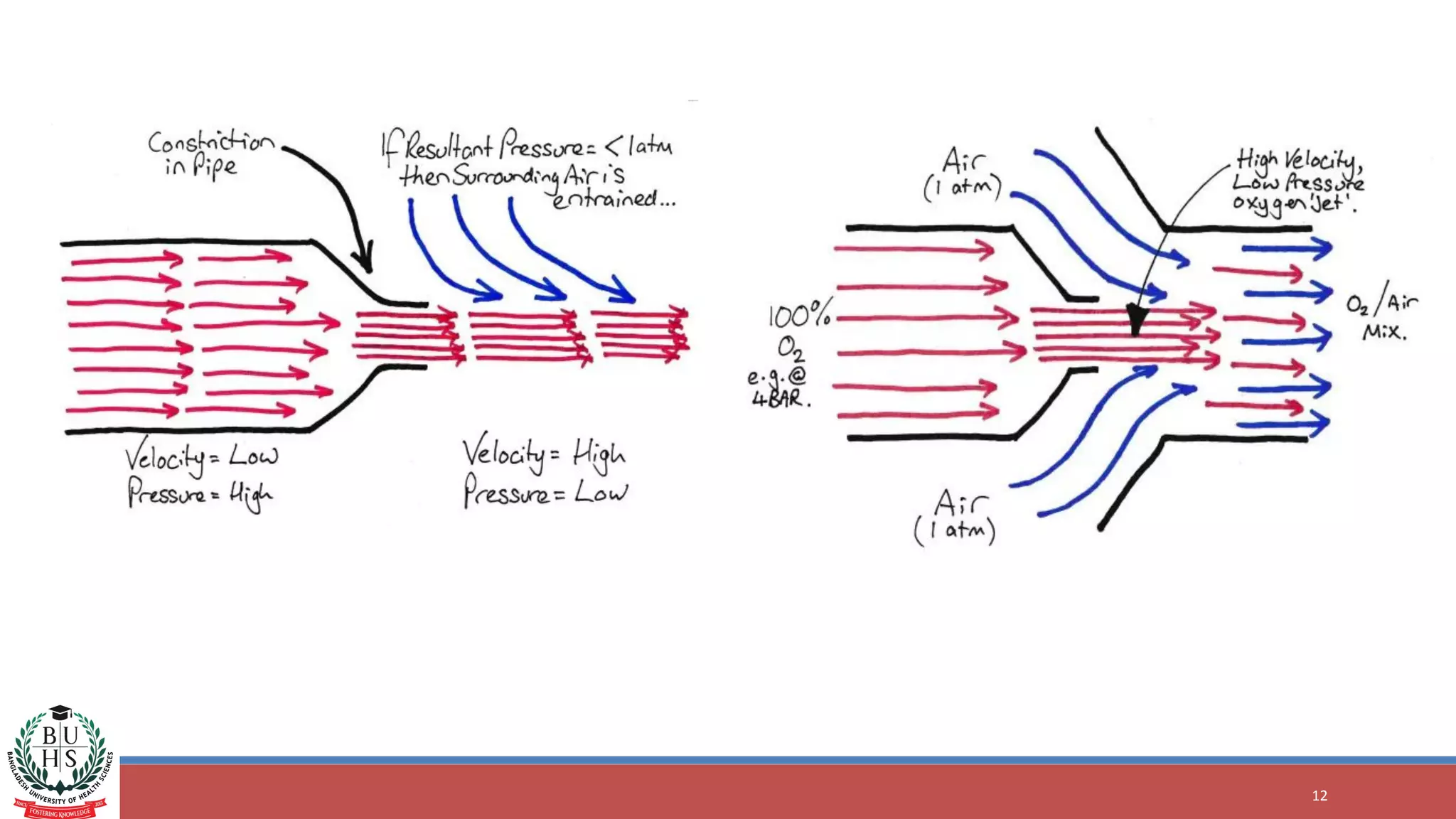
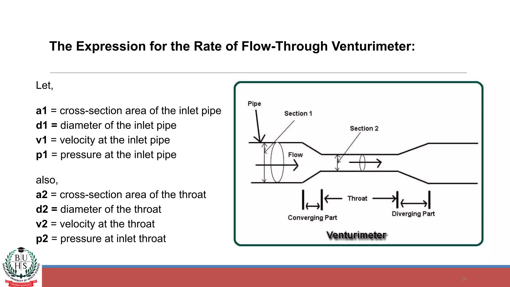
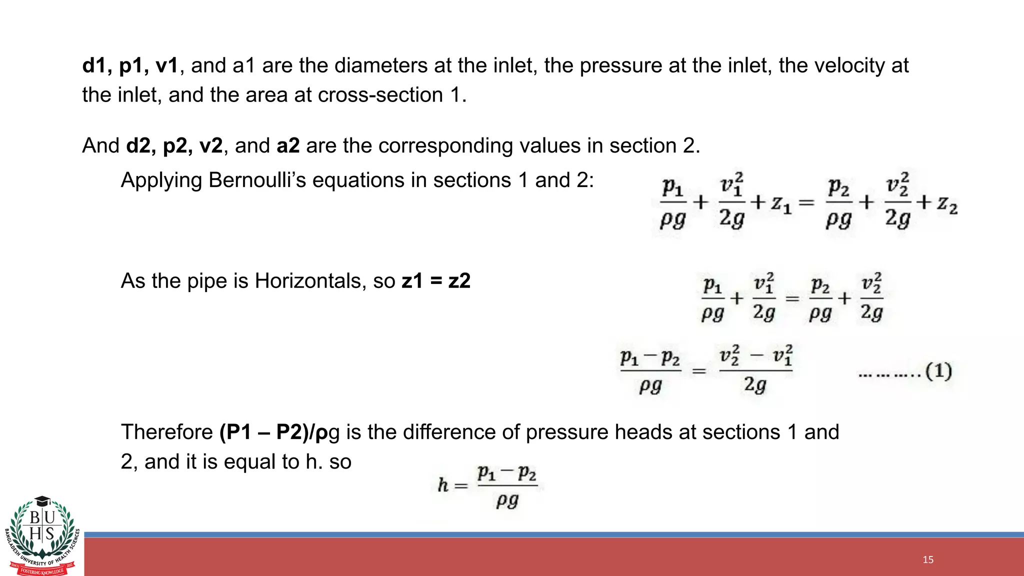
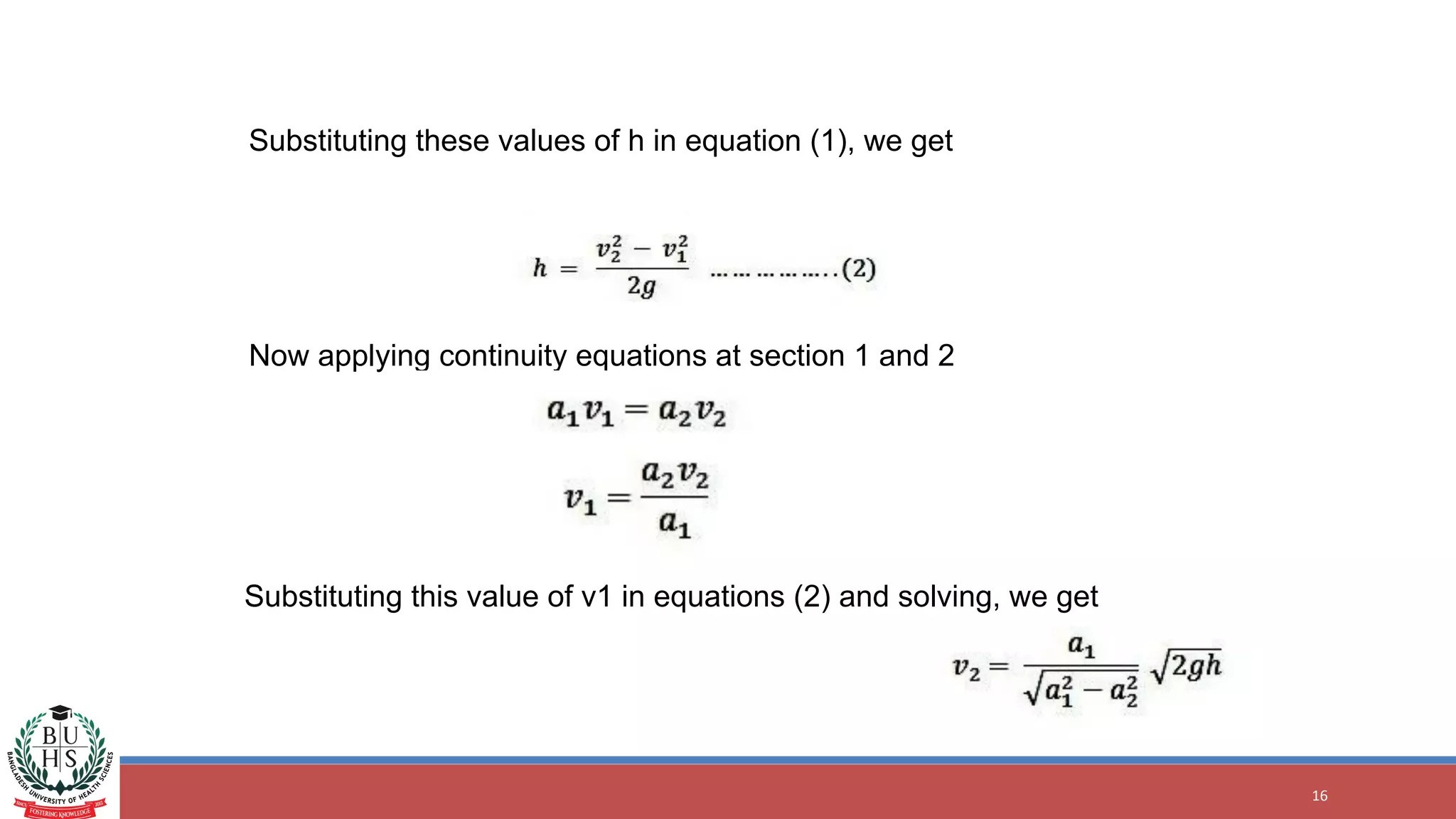
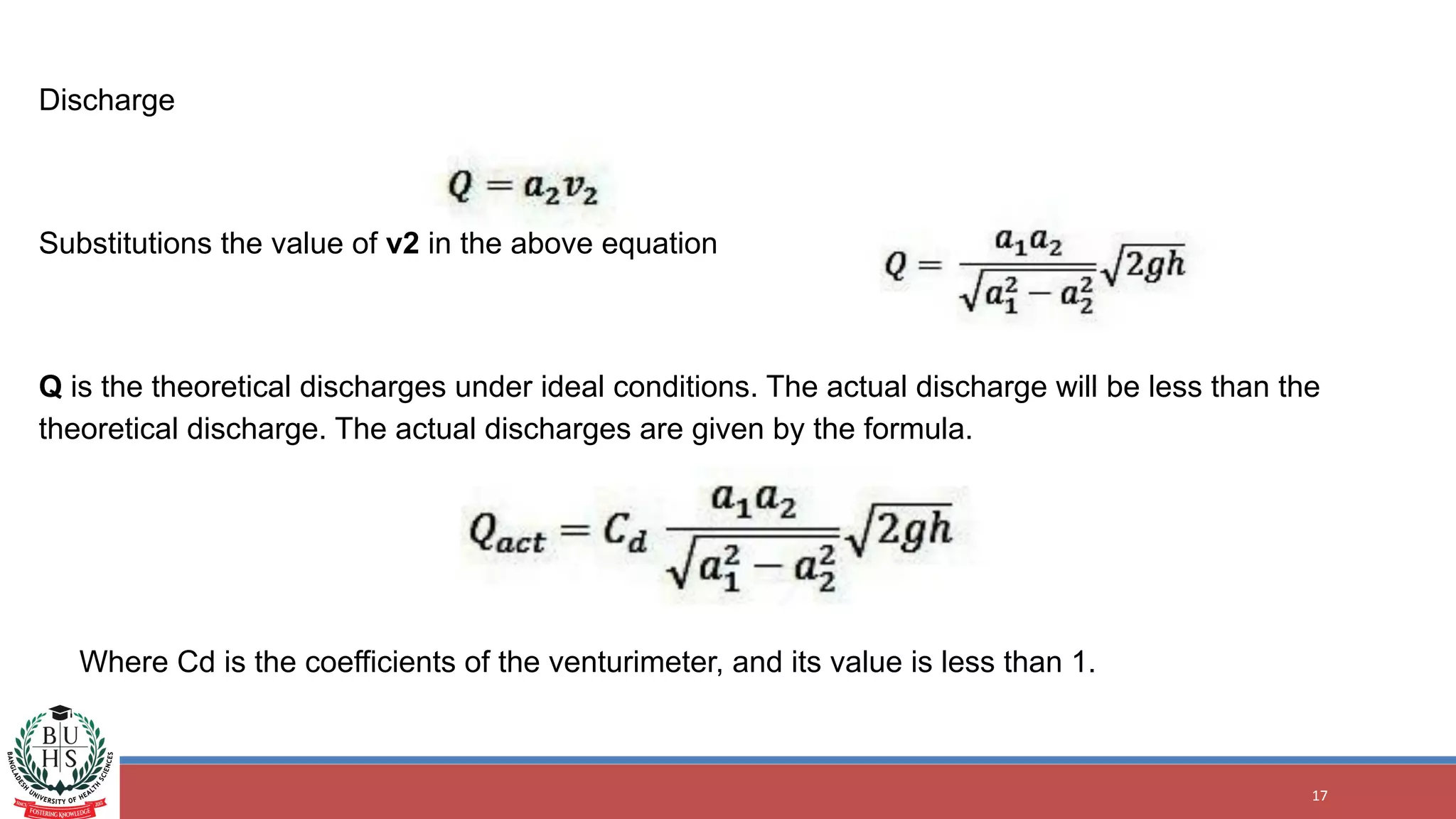
This document discusses basic equations of fluid mechanics used in a biofluid mechanics and heat transfer course. It covers the Bernoulli equation and its application to problems involving blood flow in the aorta and capillaries. It also discusses venturi meters, which use the Bernoulli principle to measure fluid flow rates. Venturi meters have a constricted section that causes velocity and pressure to change in a way that can be used to calculate flow rates. The document provides equations for calculating theoretical discharge through a venturi meter and defines related terms like cross-sectional area and velocity at different pipe sections.
This ppt is more useful for Civil Engineering students.
I have prepared this ppt during my college days as a part of semester evaluation . Hope this will help to current civil students for their ppt presentations and in many more activities as a part of their semester assessments.
I have prepared this ppt as per the syllabus concerned in the particular topic of the subject, so one can directly use it just by editing their names.
On the Analysis of the Laminar to Turbulent Flow Patterns in the Treatment of...Waqas Tariq
For a fluid, the transition from laminar to turbulent flow is a function of the fluid’s speed, direction, applied pressure, pipe length, pipe radius, fluid viscosity, and fluid density. For human breathing, all of these parameters are generally beyond control, except for the fluid\'s density and viscosity. If the human has trouble breathing, laminar flow is preferred since the person does less work for each breath. In our analysis, the pipe is the airway (or breathing tube) from lips to bifurcation; the throat/pipe radius is known or can be determined; the differential pressure is the excess pressure above or below atmospheric pressure; fluid flow rate is the person’s tidal lung volume divided by the breathing rate. We analyze 13 widely different humans (with differing values for throat length, radius, etc.) to see the effect of breathing two different fluids: air (20% oxygen, 80% nitrogen) and HeOx (20% oxygen, 80% helium). The onset of turbulent flow occurs for the critical radius, and this is calculated for each patient. For 12 patients, the critical radius is much smaller than the throat/tube radius, if HeOx is used--the flow is laminar. For all patients breathing air, the critical radius is larger than the throat/tube radius--the flow is turbulent. Thus, HeOx is shown to be superior in treating patients with breathing problems.
Lab 2 Fluid Flow Rate.pdf
MEE 491 Lab #2: Fluid Flow Rate
The goal of the fluid flow lab is to become familiar with measuring fluid pressure and flow rate
with orifice obstruction meters.
Reading: Beckwith pgs 489-576
Moran, Shapiro, Munson, and Dewitt (i.e. your thermofluids book): Ch 11, 12 & 14
Introduction
This experiment introduces you to orifice obstruction meters, which are a common tool used
to measure fluid flow rate. The experimental system includes two types of orifice obstruction
meters: flow nozzles and orifice plates. The differential pressure across the orifice obstruction
meter is needed to calculate flow rate, and so pressure measuring devices are included to
measure a) the differential pressure across the flow nozzle and b) the differential pressure across
the orifice plate. Figure 1 illustrates the experimental system and its relevant components.
Air from the room enters the plenum chamber through the nozzle. The air then flows through
flexible black tubing and into a transparent circular duct that is instrumented with the orifice
plate. Lastly the air flow enters the vacuum pump via more flexible black tubing and is returned
to the room via the vacuum pumps outlet. Variable air flow through the system can be achieved
by a rheostat knob that controls the vacuum pump. We will assume that any leaks in the system
are negligible. Since the obstruction meters are connected in series, both obstruction meters
measure the same mass flow rate (i.e. conservation of mass).
In the case of the flow nozzles, two different sizes are provided. Both nozzles are
standardized ASME long-radius flow nozzles with diameters of 1.265 cm and 2.530 cm for the
small and medium nozzles, respectively. The orifice plate has a diameter of 0.795 in and is
located in a pipe with a diameter of 2 in.
Figure 1. Photograph of the experimental system and relevant components for
part A of this lab
The discharge coefficient, CD, is a very important performance parameter for an orifice
obstruction meter. The discharge coefficient tells you the ratio of the actual orifice flow rate,
Qactual, to the ideal orifice flow rate, Qideal:
𝐶! =
!!"#$!%
!!"#$%
[1]
The ideal flow rate corresponds to the flow rate as derived from Bernoulli’s equation. Two of
the assumptions that Bernoulli’s equation makes are isentropic and incompressible flow. While
these are good approximations in many engineering situations, no real system is every truly
isentropic and incompressible. Hence the discharge coefficient is always less than 1. In this lab
you will determine the discharge coefficient for the nozzles as well as the orifice plate.
Procedure
• With the small nozzle measure at five different steady-state (i.e. make sure pressures are
not changing with time) flow rates measure:
o The differential pressure across the flow nozzle.
o The differential pressure across the orifice plate wi ..
Rev. August 2014 ME495 - Pipe Flow Characteristics… Page .docxjoyjonna282
Rev. August 2014 ME495 - Pipe Flow Characteristics… Page 2
2
ME495—Thermo Fluids Laboratory
~~~~~~~~~~~~~~
PIPE FLOW CHARACTERISTICS
AND PRESSURE TRANSDUCER
CALIBRATION
~~~~~~~~~~~~~~
PREPARED BY: GROUP LEADER’S NAME
LAB PARTNERS: NAME
NAME
NAME
TIME/DATE OF EXPERIMENT: TIME , DATE
~~~~~~~~~~~~~~
OBJECTIVE— The objectives of this experiment are
to: a) observe the characteristics of flow in a pipe,
b) evaluate the flow rate in a pipe using velocity
and pressure difference measurements, and c)
perform the calibration of a pressure transducer.
Upon completing this experiment you should have
learned (i) how to measure the flow rate and average
velocity in a pipe using a Pitot tube and/or a resistance
flow meter, and (ii) how to classify the general
characteristics of a pipe flow.
Nomenclature
a = speed of sound, m/s
A = area, m
2
C = discharge coefficient, dimensionless
d = pipe diameter, m
d0 = orifice diameter, m
E = velocity approach factor, dimensionless
f = Darcy friction factor, dimensionless
K0 = flow coefficient, dimensionless
k = ratio of specific heats (cp/cv), dimensionless
L = length of pipe, m
M = Mach number, dimensionless
p = pressure, Pa
p0 = stagnation pressure, Pa
p1, p2 = pressure at two axial locations along a
pipe, Pa
Q = volumetric flow rate, m
3
/s
R = specific gas constant, J·kg/K
Re = Reynolds number, dimensionless
T = temperature, K
V = local velocity, m/s
V = average velocity, m/s
Y = adiabatic expansion factor, dimensionless
= ratio of orifice diameter to pipe diameter,
dimensionless
p = pressure drop across an orifice meter, Pa
= dynamic viscosity, Pa·s
= air density, kg/m3
INTRODUCTION— The flow of a fluid (liquid or
gas) through pipes or ducts is a common part of many
engineering systems. Household applications include
the flow of water in copper pipes, the flow of natural
gas in steel pipes, and the flow of heated air through
metal ducts of rectangular cross-section in a forced-air
furnace system. Industrial applications range from the
flow of liquid plastics in a manufacturing plant, to the
flow of yogurt in a food-processing plant. Because the
purpose of a piping system is to transport a desired
quantity of fluid, it is important to understand the
various methods of measuring the flow rate.
In order to work with a fluid system, and certainly to
design a fluid system that will deliver a prescribed
flow, it is necessary to understand certain fundamental
aspects of the fluid flow. For this, one should be able
to answer questions like: Are compressibility effects
important? Is the flow laminar or turbulent? Is the
viscosity of the fluid important or not? Is the flow
steady or varying with time? What are the primary
forces of importance? For internal ...
VENTURIMETER -Application of Bernoulli's LawKundan Kumar
A venturimeter is essentially a short pipe consisting of two conical parts with a short portion of uniform cross-section in between. This short portion has the minimum area and is known as the throat. The two conical portions have the same base diameter, but one is having a shorter length with a larger cone angle while the other is having a larger length with a smaller cone angle.
Mechanics of fluids is extremely important in many areas of engineering and science. Examples are:
Mechanical engineering:
Pipeline projects.
Design of tanks.
Design of pumps, turbines, air-conditioning equipment.
Petroleum Engineering
Mud logging, cementing.
Chemical Engineering
Design of chemical processing equipment.
IJRET : International Journal of Research in Engineering and Technology is an international peer reviewed, online journal published by eSAT Publishing House for the enhancement of research in various disciplines of Engineering and Technology. The aim and scope of the journal is to provide an academic medium and an important reference for the advancement and dissemination of research results that support high-level learning, teaching and research in the fields of Engineering and Technology. We bring together Scientists, Academician, Field Engineers, Scholars and Students of related fields of Engineering and TechnologyIJRET : International Journal of Research in Engineering and Technology is an international peer reviewed, online journal published by eSAT Publishing House for the enhancement of research in various disciplines of Engineering and Technology. The aim and scope of the journal is to provide an academic medium and an important reference for the advancement and dissemination of research results that support high-level learning, teaching and research in the fields of Engineering and Technology. We bring together Scientists, Academician, Field Engineers, Scholars and Students of related fields of Engineering and Technology
Comparison of flow analysis of a sudden and gradual change of pipe diameter u...eSAT Journals
Abstract This paper describes an analytical approach to describe the areas where Pipes (used for flow of fluids) are mostly susceptible to damage and tries to visualize the flow behaviour in various geometric conditions of a pipe. Fluent software was used to plot the characteristics of the flow and gambit software was used to design the 2D model. Two phase Computational fluid dynamics calculations, using K-epsilon model were employed. This simulation gives the values of pressure and velocity contours at various sections of the pipe in which water as a media. A comparison was made with the sudden and gradual change of pipe diameter (i.e., expansion and contraction of the pipe). The numerical results were validated against experimental data from the literature and were found to be in good agreement. Index Terms: gambit, fluent software.
Quality defects in TMT Bars, Possible causes and Potential Solutions.PrashantGoswami42
Maintaining high-quality standards in the production of TMT bars is crucial for ensuring structural integrity in construction. Addressing common defects through careful monitoring, standardized processes, and advanced technology can significantly improve the quality of TMT bars. Continuous training and adherence to quality control measures will also play a pivotal role in minimizing these defects.
Vaccine management system project report documentation..pdfKamal Acharya
The Division of Vaccine and Immunization is facing increasing difficulty monitoring vaccines and other commodities distribution once they have been distributed from the national stores. With the introduction of new vaccines, more challenges have been anticipated with this additions posing serious threat to the already over strained vaccine supply chain system in Kenya.
Automobile Management System Project Report.pdfKamal Acharya
The proposed project is developed to manage the automobile in the automobile dealer company. The main module in this project is login, automobile management, customer management, sales, complaints and reports. The first module is the login. The automobile showroom owner should login to the project for usage. The username and password are verified and if it is correct, next form opens. If the username and password are not correct, it shows the error message.
When a customer search for a automobile, if the automobile is available, they will be taken to a page that shows the details of the automobile including automobile name, automobile ID, quantity, price etc. “Automobile Management System” is useful for maintaining automobiles, customers effectively and hence helps for establishing good relation between customer and automobile organization. It contains various customized modules for effectively maintaining automobiles and stock information accurately and safely.
When the automobile is sold to the customer, stock will be reduced automatically. When a new purchase is made, stock will be increased automatically. While selecting automobiles for sale, the proposed software will automatically check for total number of available stock of that particular item, if the total stock of that particular item is less than 5, software will notify the user to purchase the particular item.
Also when the user tries to sale items which are not in stock, the system will prompt the user that the stock is not enough. Customers of this system can search for a automobile; can purchase a automobile easily by selecting fast. On the other hand the stock of automobiles can be maintained perfectly by the automobile shop manager overcoming the drawbacks of existing system.
Water scarcity is the lack of fresh water resources to meet the standard water demand. There are two type of water scarcity. One is physical. The other is economic water scarcity.
Democratizing Fuzzing at Scale by Abhishek Aryaabh.arya
Presented at NUS: Fuzzing and Software Security Summer School 2024
This keynote talks about the democratization of fuzzing at scale, highlighting the collaboration between open source communities, academia, and industry to advance the field of fuzzing. It delves into the history of fuzzing, the development of scalable fuzzing platforms, and the empowerment of community-driven research. The talk will further discuss recent advancements leveraging AI/ML and offer insights into the future evolution of the fuzzing landscape.
Forklift Classes Overview by Intella PartsIntella Parts
Discover the different forklift classes and their specific applications. Learn how to choose the right forklift for your needs to ensure safety, efficiency, and compliance in your operations.
For more technical information, visit our website https://intellaparts.com
COLLEGE BUS MANAGEMENT SYSTEM PROJECT REPORT.pdfKamal Acharya
The College Bus Management system is completely developed by Visual Basic .NET Version. The application is connect with most secured database language MS SQL Server. The application is develop by using best combination of front-end and back-end languages. The application is totally design like flat user interface. This flat user interface is more attractive user interface in 2017. The application is gives more important to the system functionality. The application is to manage the student’s details, driver’s details, bus details, bus route details, bus fees details and more. The application has only one unit for admin. The admin can manage the entire application. The admin can login into the application by using username and password of the admin. The application is develop for big and small colleges. It is more user friendly for non-computer person. Even they can easily learn how to manage the application within hours. The application is more secure by the admin. The system will give an effective output for the VB.Net and SQL Server given as input to the system. The compiled java program given as input to the system, after scanning the program will generate different reports. The application generates the report for users. The admin can view and download the report of the data. The application deliver the excel format reports. Because, excel formatted reports is very easy to understand the income and expense of the college bus. This application is mainly develop for windows operating system users. In 2017, 73% of people enterprises are using windows operating system. So the application will easily install for all the windows operating system users. The application-developed size is very low. The application consumes very low space in disk. Therefore, the user can allocate very minimum local disk space for this application.
Pile Foundation by Venkatesh Taduvai (Sub Geotechnical Engineering II)-conver...
Lecture 6_Basic Equations of Fluid Mechanics.pptx.pdf
1. Biofluid Mechanics and Heat Transfer
Course Code: 04041115
Lecture 06: Basic Equations of Fluid Mechanics
Date: 31/07/2023
Course Teacher: Tohfatul Jinan
Lecturer
Department of Biomedical Engineering BUHS
BANGLADESH UNIVERSITY OF HEALTH SCIENCES
Department of Biomedical Engineering
1
8. Problem-3
8
In an adult, the aorta's radius is normally 1.5cm,
and blood moves through it at an average
speed of 30cm/s. If the typical capillary has a
radius of 5 x 10⁻⁶ m, and blood passes through
them with a velocity of 0.1cm/s, approximately
how many capillaries are in the body?
Determine the mass flow rate of blood in the
capillaries and aorta if the blood density is 1060
kg/m??(HW)
9. 9
Venturi Meters
● Venturi meters are used to measures the flow rate of a
fluid through a pipe. This is an application of
Bernoulli’s equation.
● Venturi meter theory works on the Bernoulli equation
such that the velocity increases as the pressure
decreases.
● This theory states that when the cross-sectional area
of the flow decreases, a pressure difference between
the different regions of the flow is created, and it helps
to measure the difference under pressure.
● This pressure differential helps to measure the
discharge inflow
10. Venturi effect
10
The Venturi effect is the reduction in fluid pressure that results when a fluid flows through
a constricted section (or choke) of a pipe.
11. Venturi masks
11
Venturi masks are low-flow masks
that use the Bernoulli principle to
entrain room air when pure oxygen
is delivered through a small orifice,
resulting in a large total flow at
predictable Fio2.
13. HW
13
1. Principle of venturi mask
2. Difference between venturi mask and oxygen mask
14. The Expression for the Rate of Flow-Through Venturimeter:
14
Let,
a1 = cross-section area of the inlet pipe
d1 = diameter of the inlet pipe
v1 = velocity at the inlet pipe
p1 = pressure at the inlet pipe
also,
a2 = cross-section area of the throat
d2 = diameter of the throat
v2 = velocity at the throat
p2 = pressure at inlet throat
15. 15
d1, p1, v1, and a1 are the diameters at the inlet, the pressure at the inlet, the velocity at
the inlet, and the area at cross-section 1.
And d2, p2, v2, and a2 are the corresponding values in section 2.
Applying Bernoulli’s equations in sections 1 and 2:
As the pipe is Horizontals, so z1 = z2
Therefore (P1 – P2)/ρg is the difference of pressure heads at sections 1 and
2, and it is equal to h. so
16. 16
Substituting these values of h in equation (1), we get
Now applying continuity equations at section 1 and 2
Substituting this value of v1 in equations (2) and solving, we get
17. 17
Discharge
Substitutions the value of v2 in the above equation
Q is the theoretical discharges under ideal conditions. The actual discharge will be less than the
theoretical discharge. The actual discharges are given by the formula.
Where Cd is the coefficients of the venturimeter, and its value is less than 1.