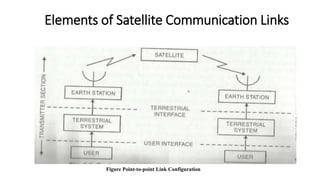
This document discusses elements of satellite communication links. It describes:
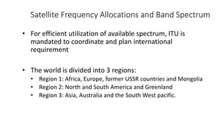
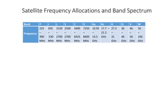
1) Satellite frequency allocations and bands from 225MHz to 100GHz that are divided among three regions.
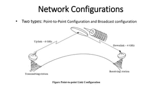
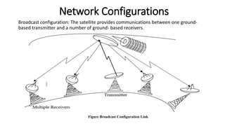
2) Two types of network configurations - point-to-point and broadcast.
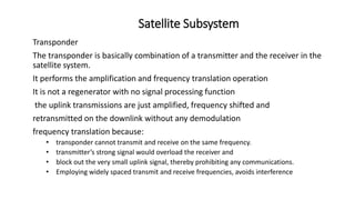
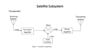
3) The satellite subsystem including transponders that receive, amplify, and retransmit signals on different frequencies to avoid interference.


![Satellite communications[1]](https://cdn.slidesharecdn.com/ss_thumbnails/satellitecommunications1-130416091107-phpapp01-thumbnail.jpg?width=640&height=640&fit=bounds)


