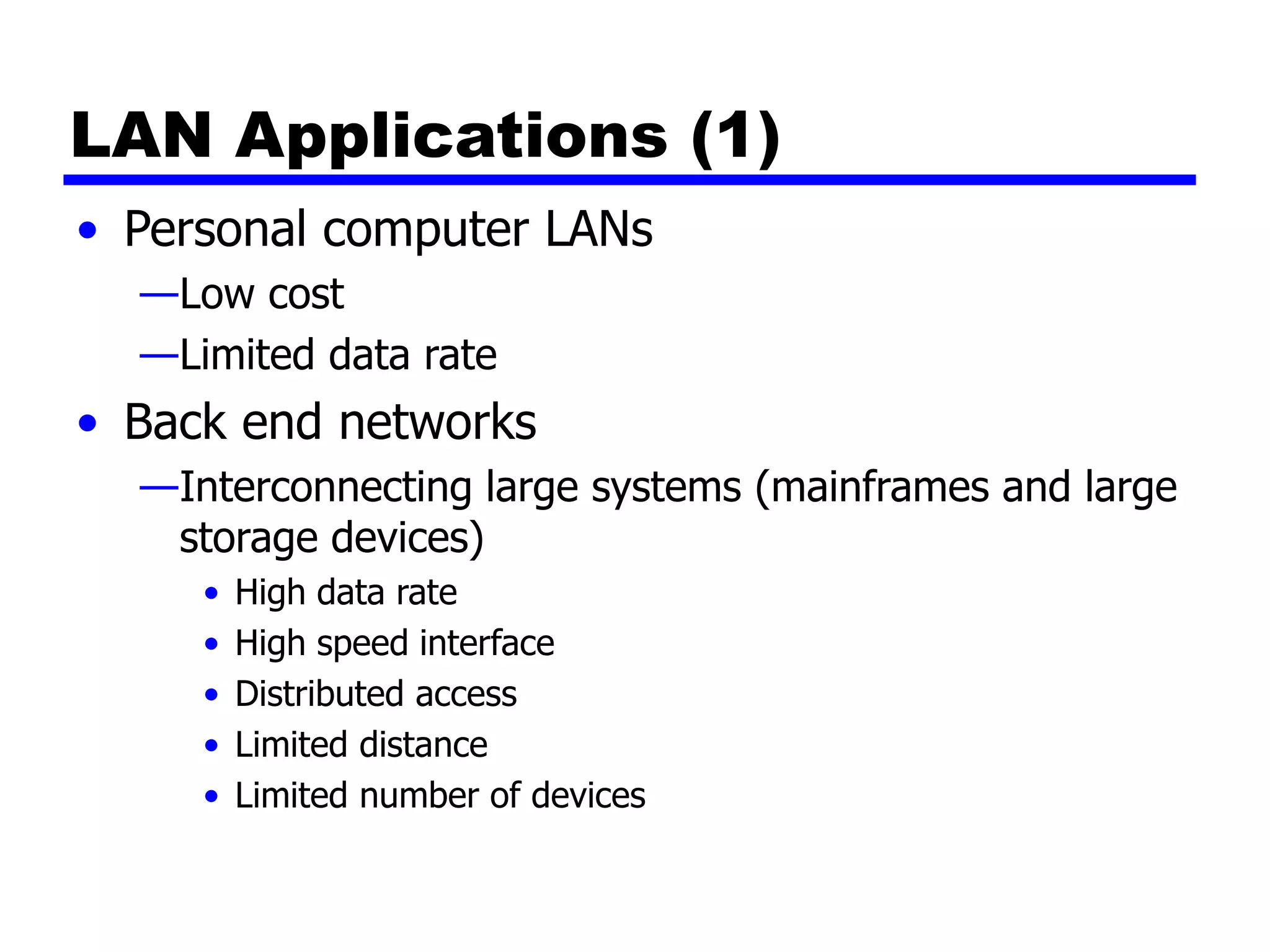
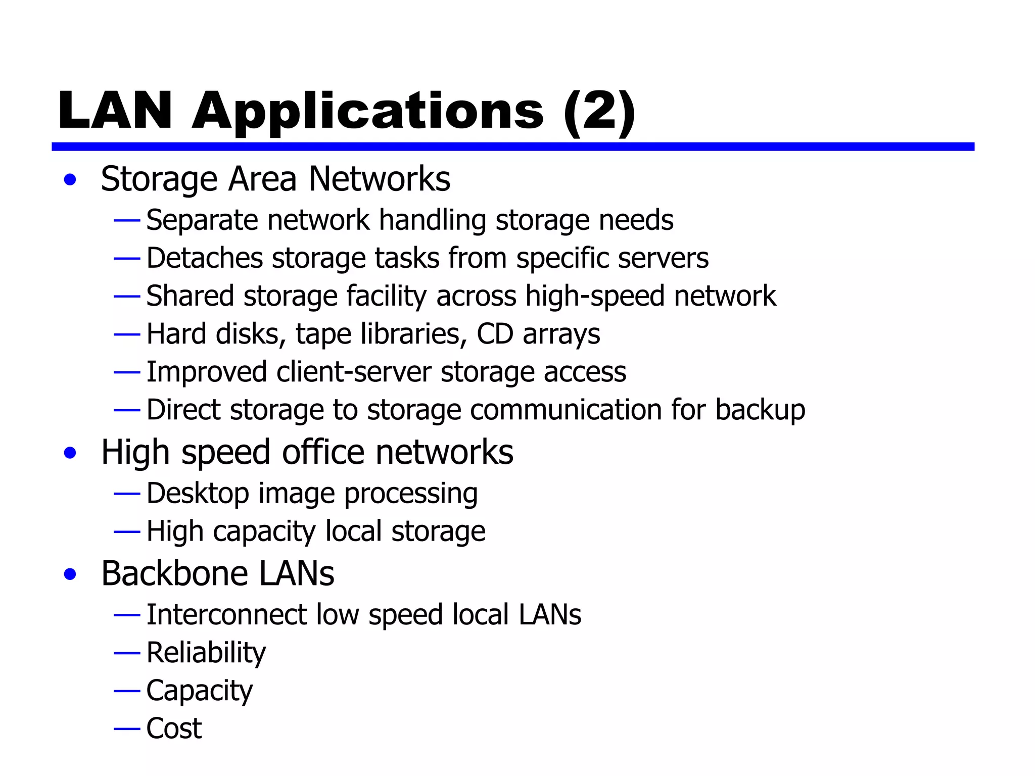
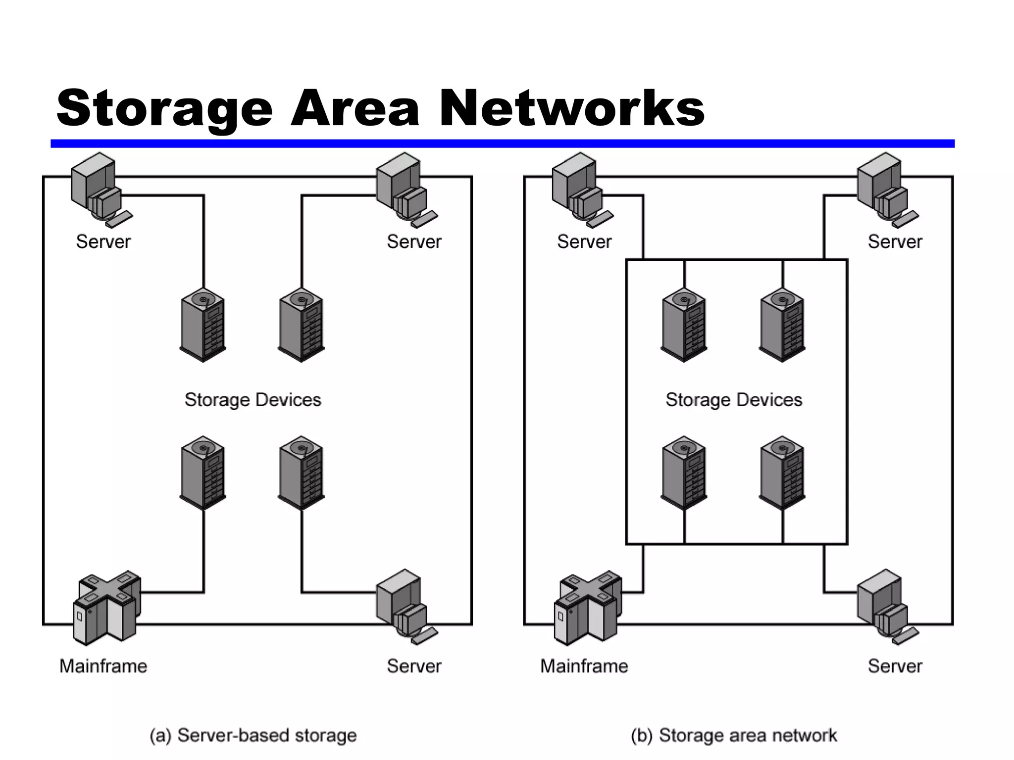
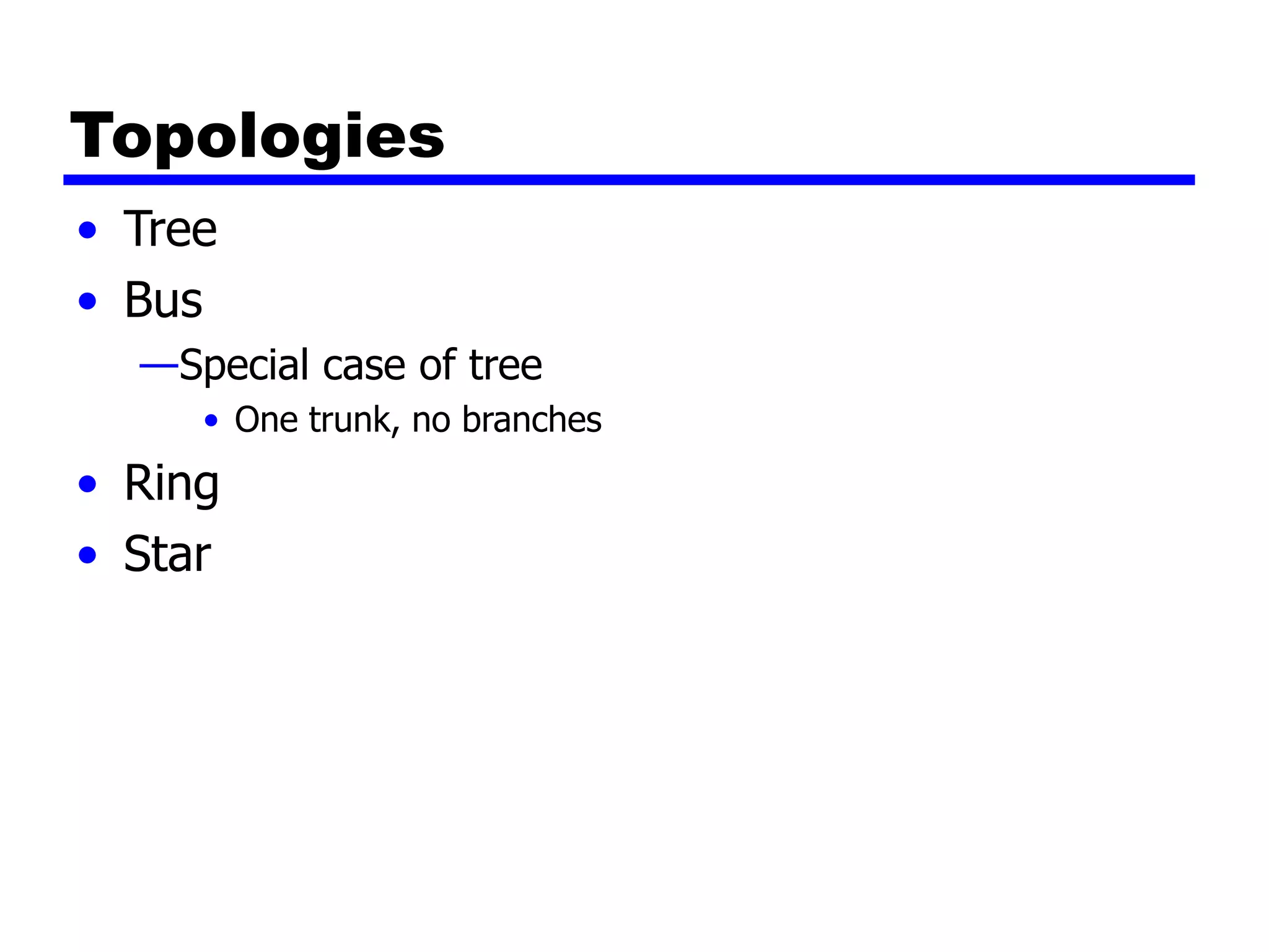
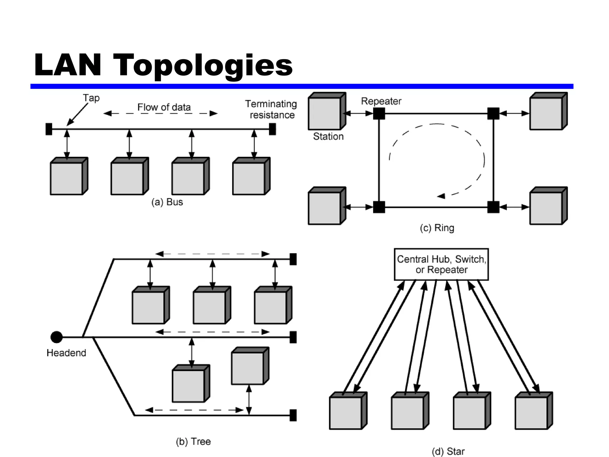
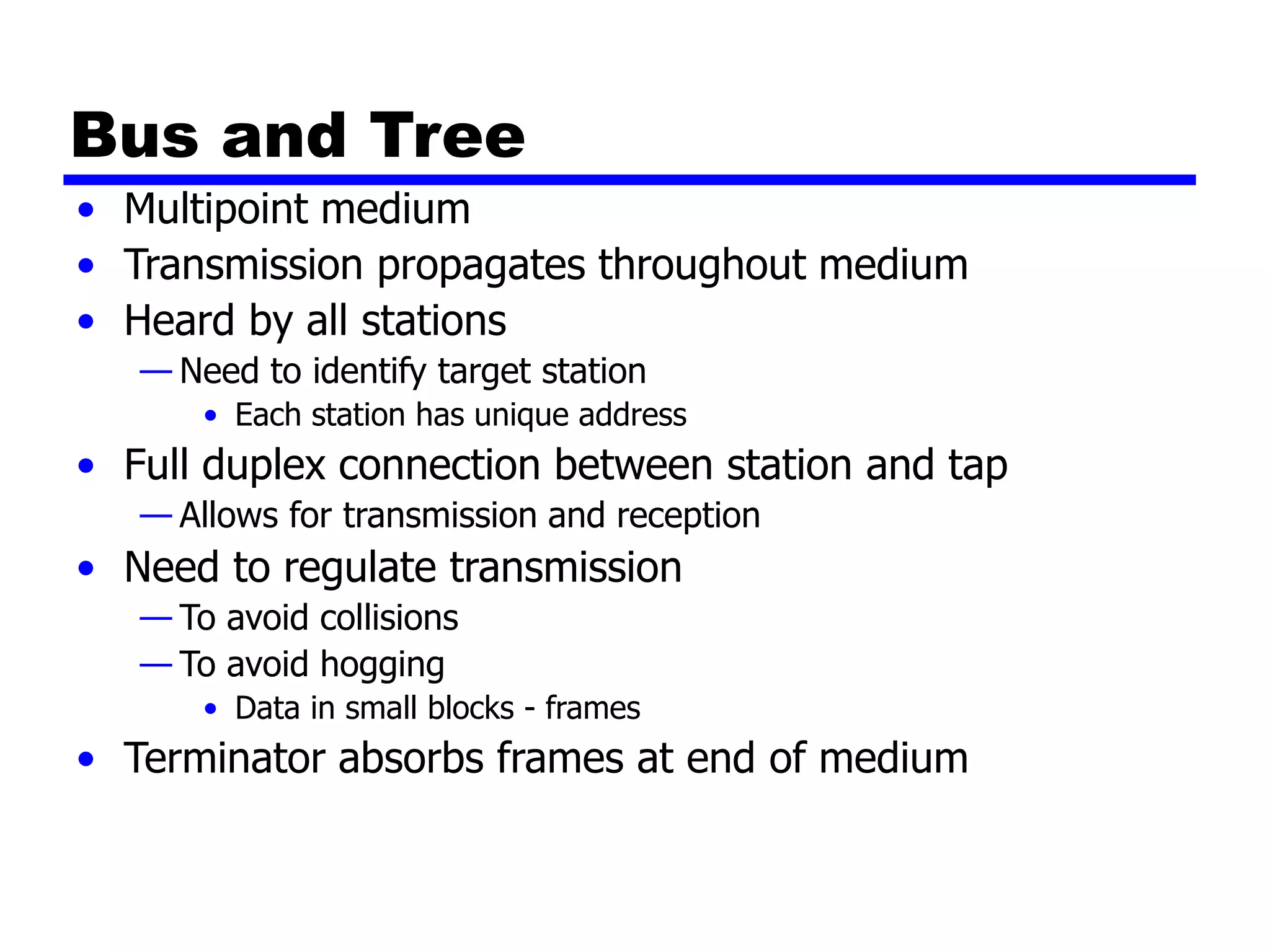
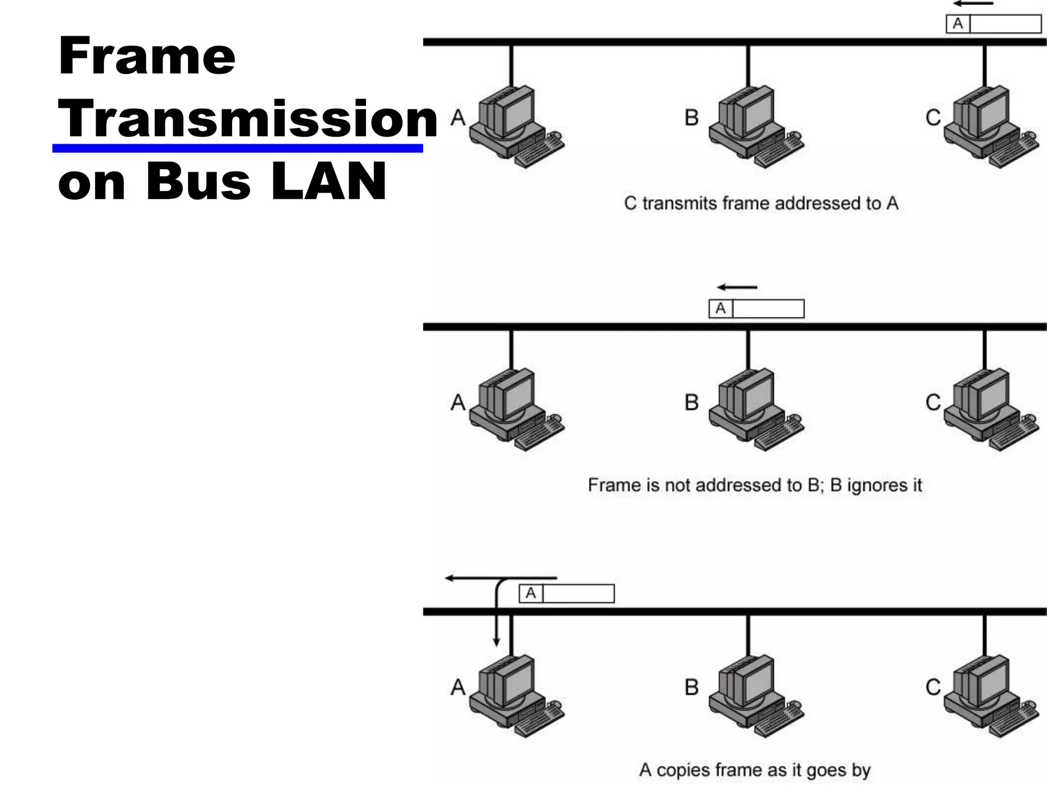
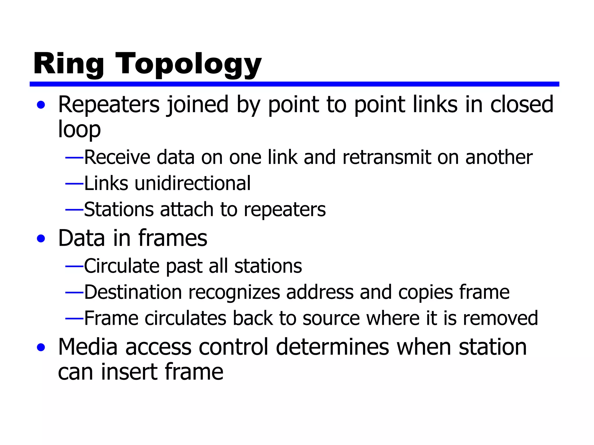
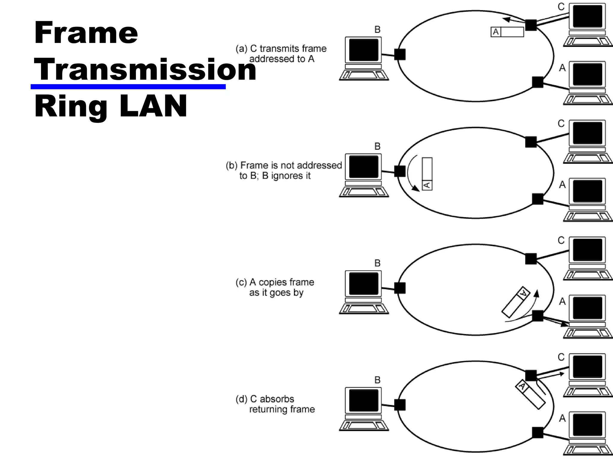
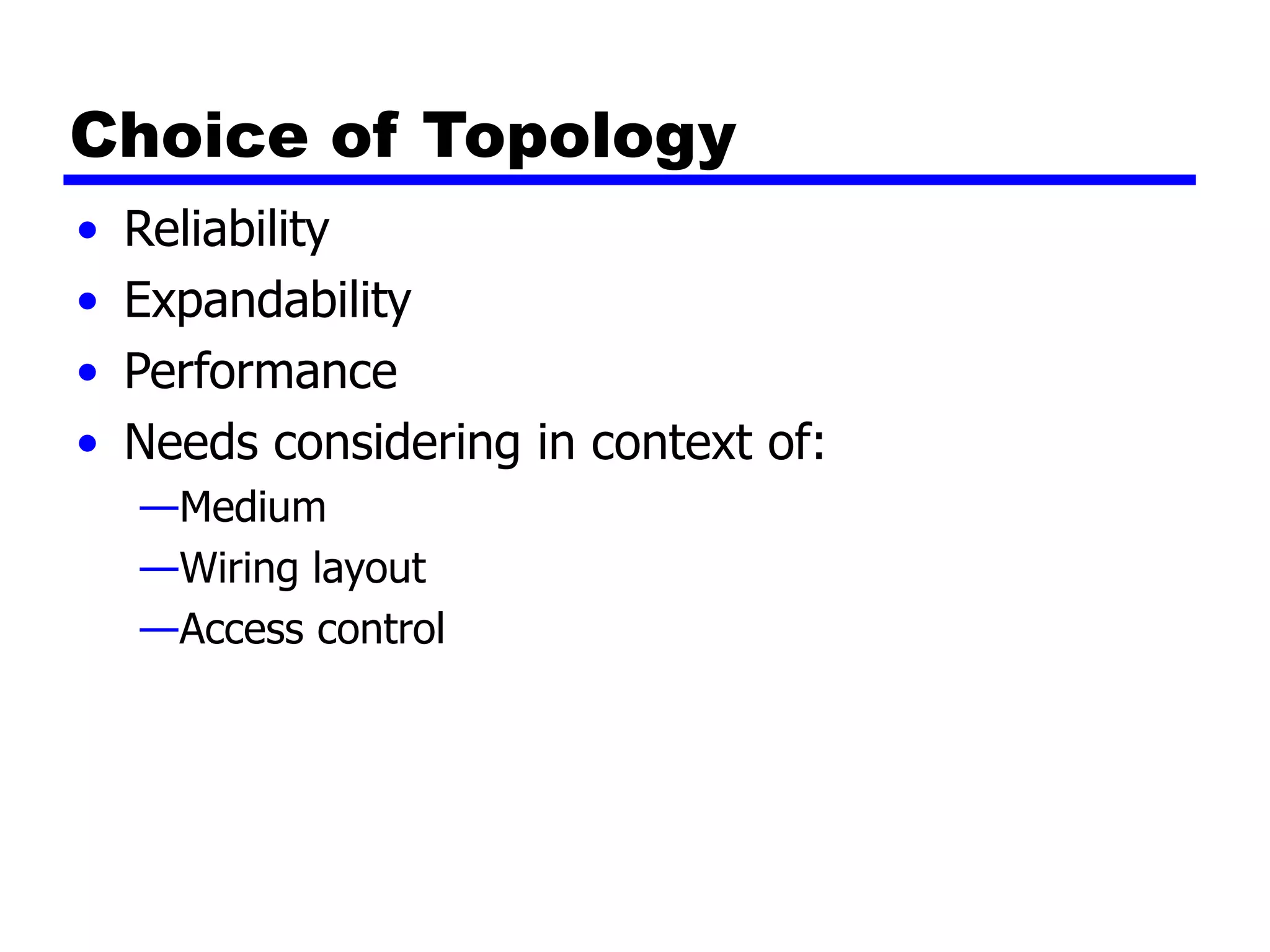
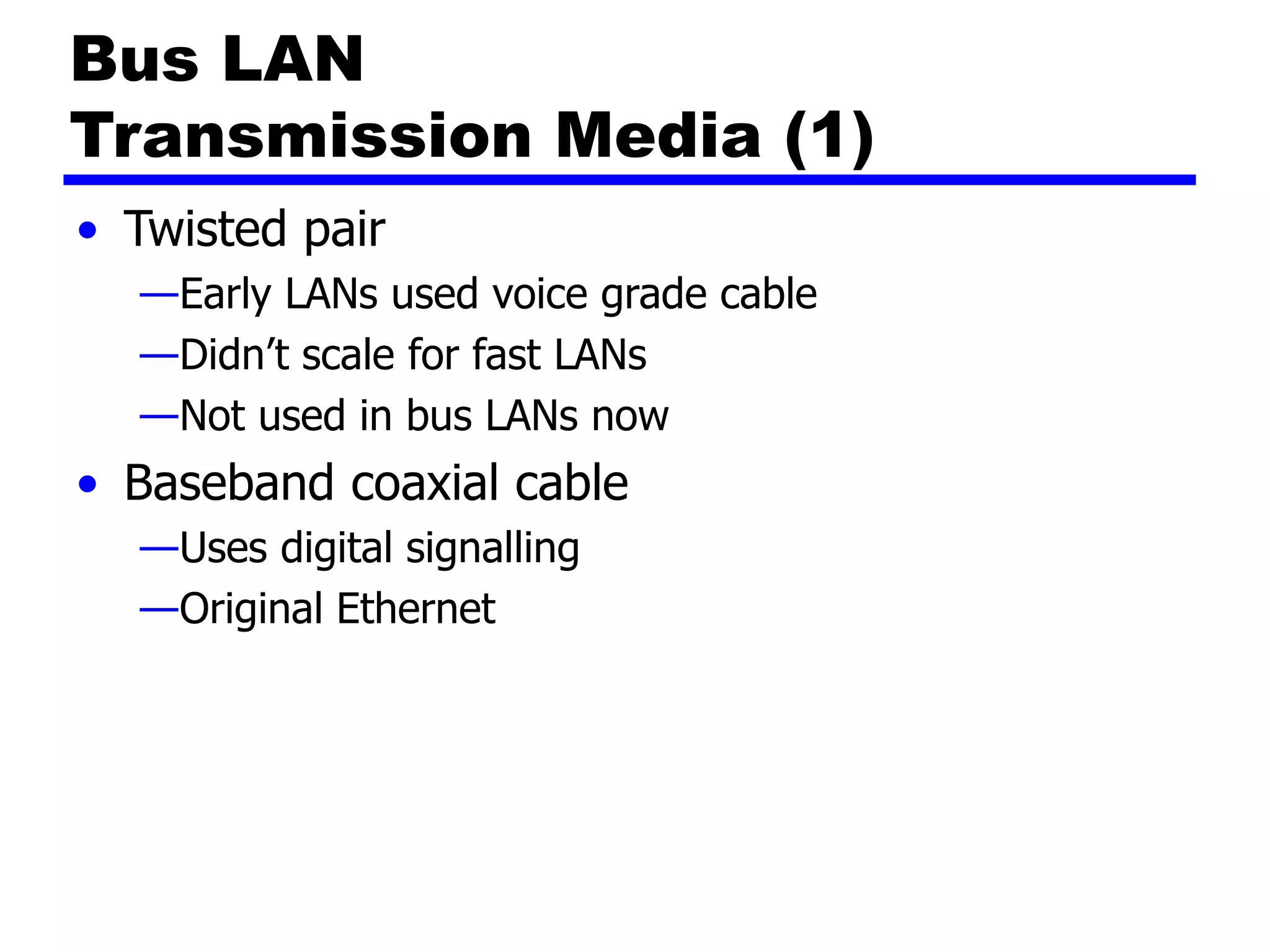
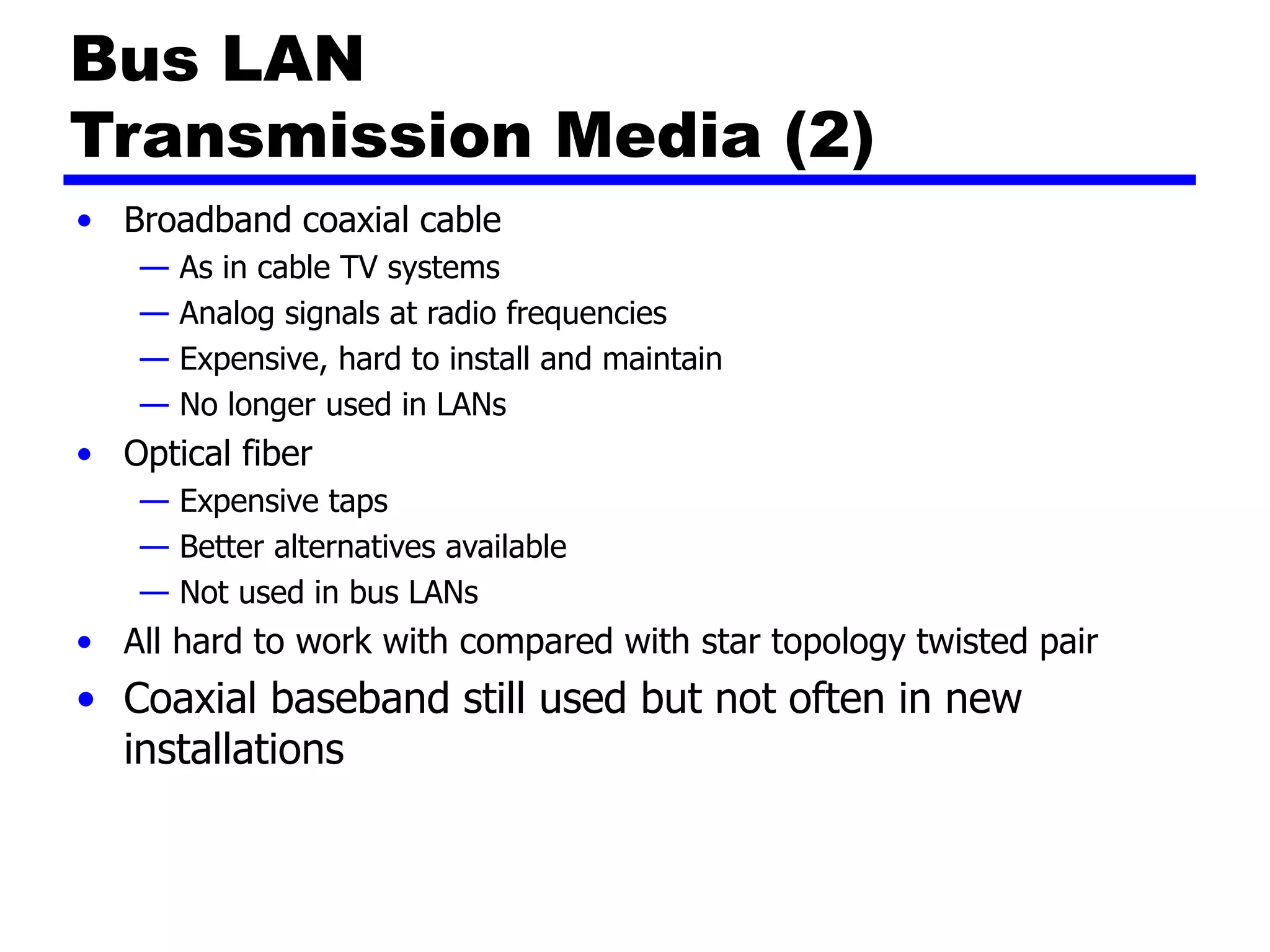
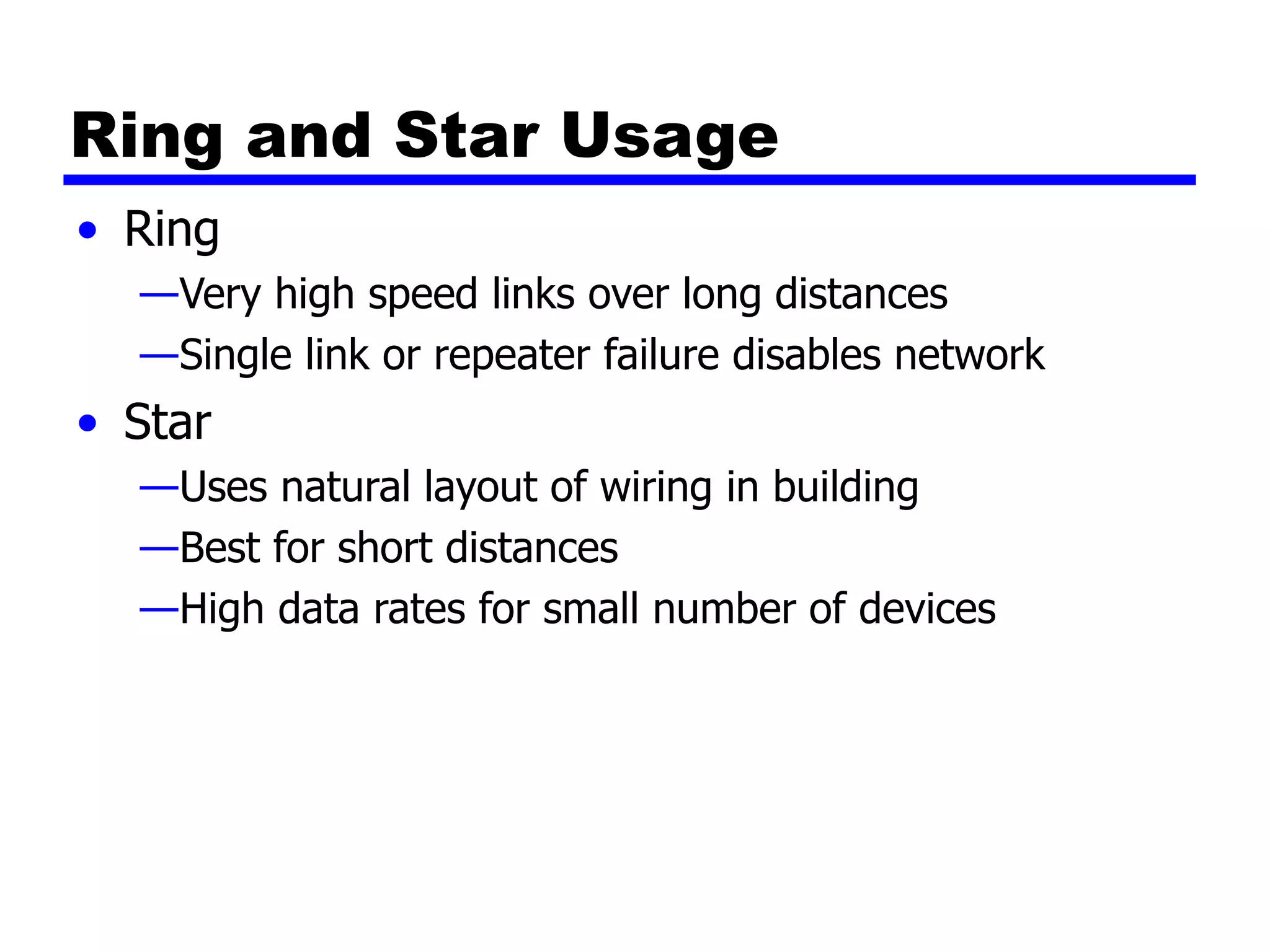
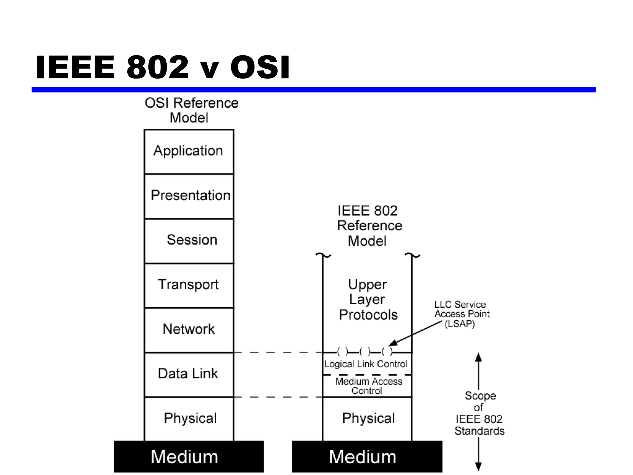
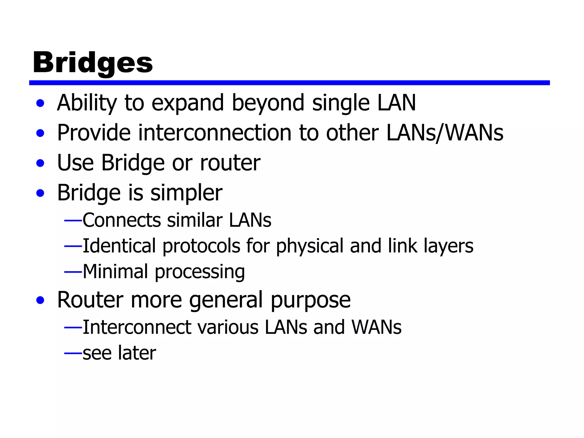
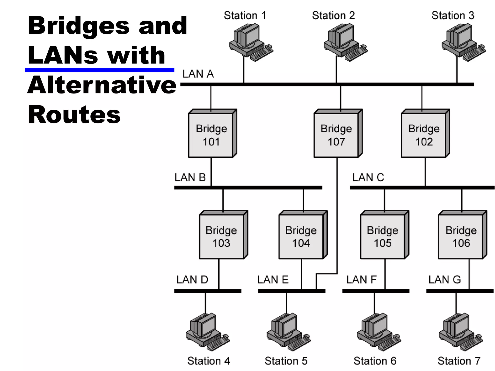
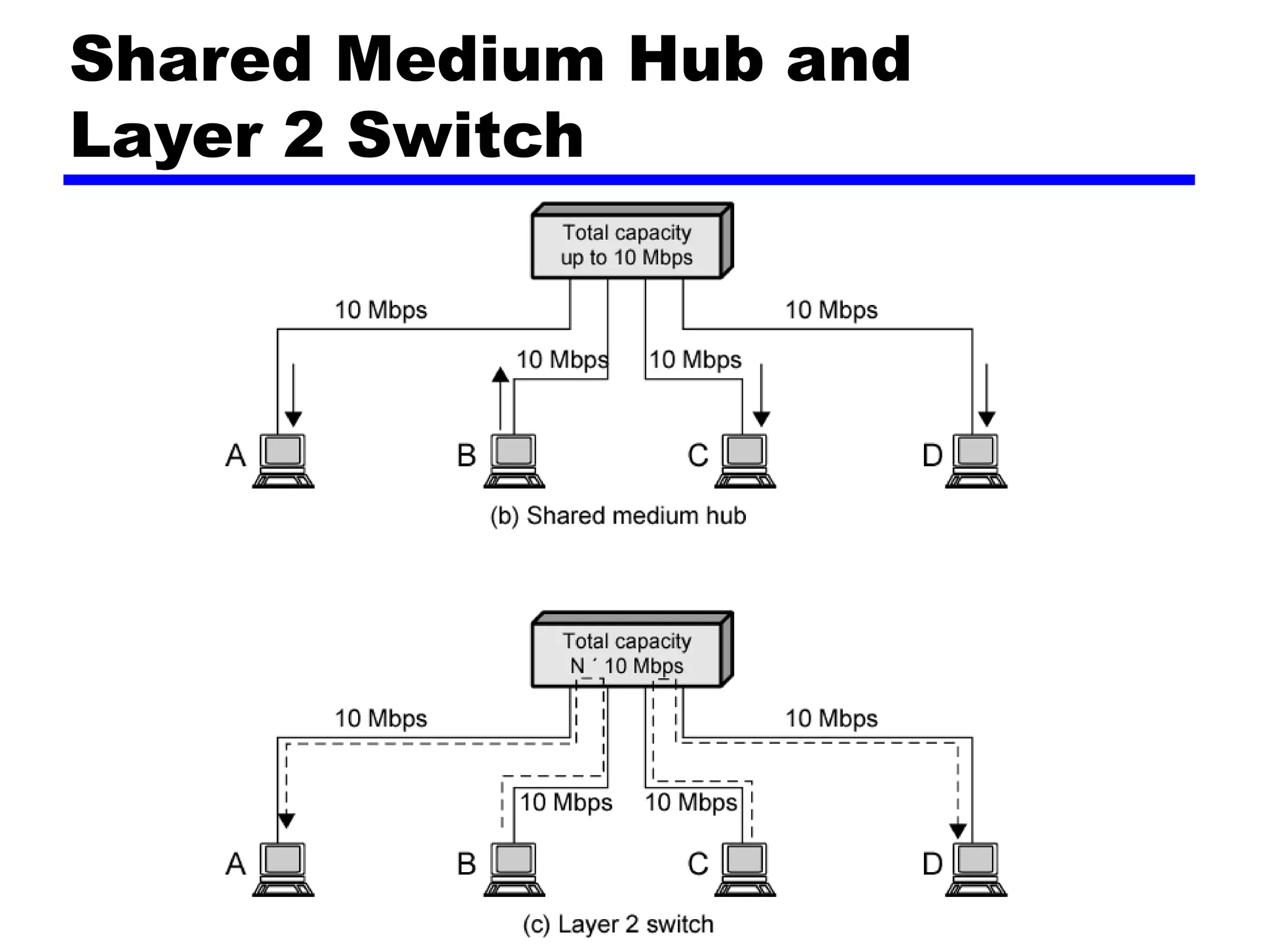
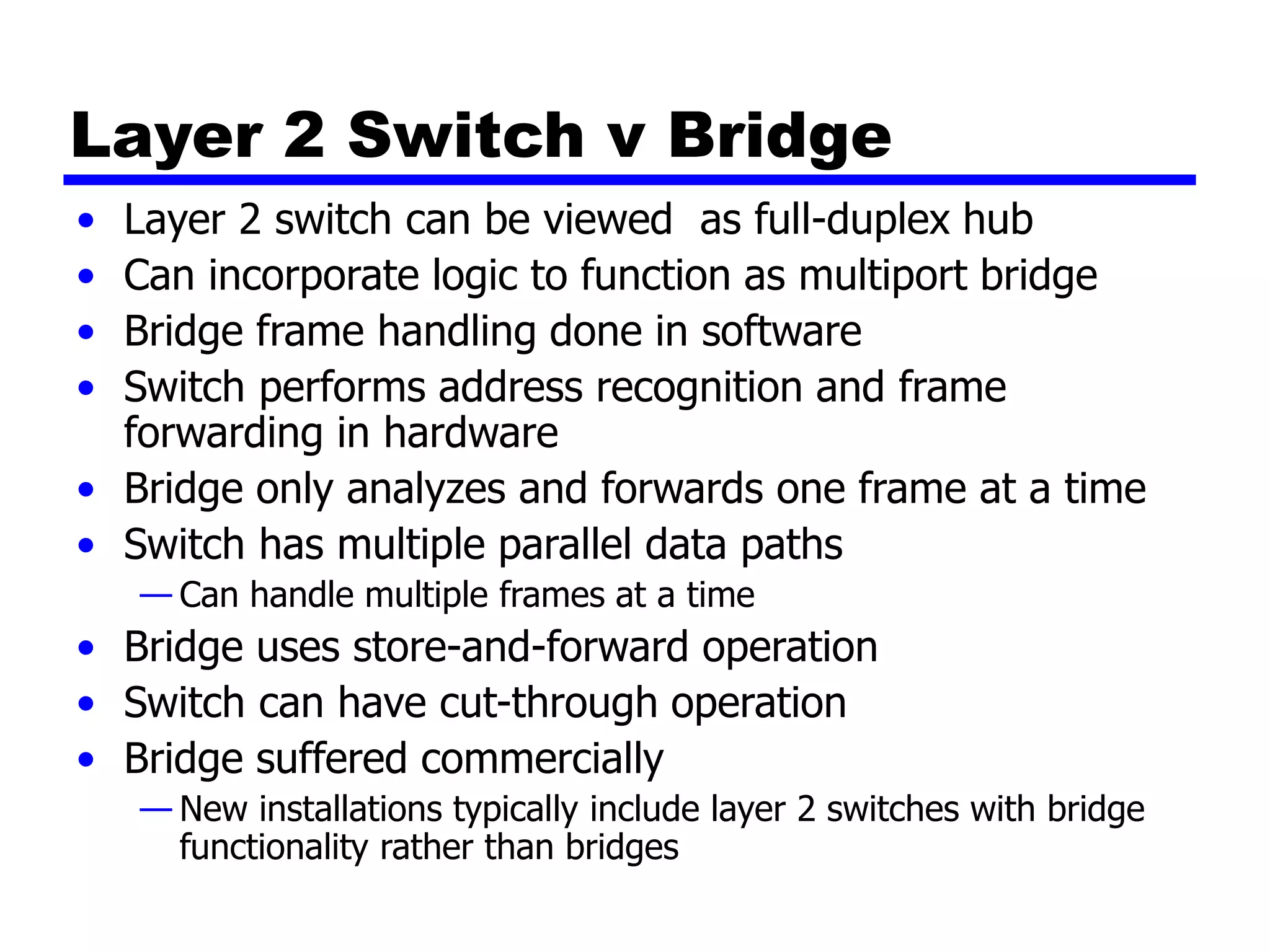
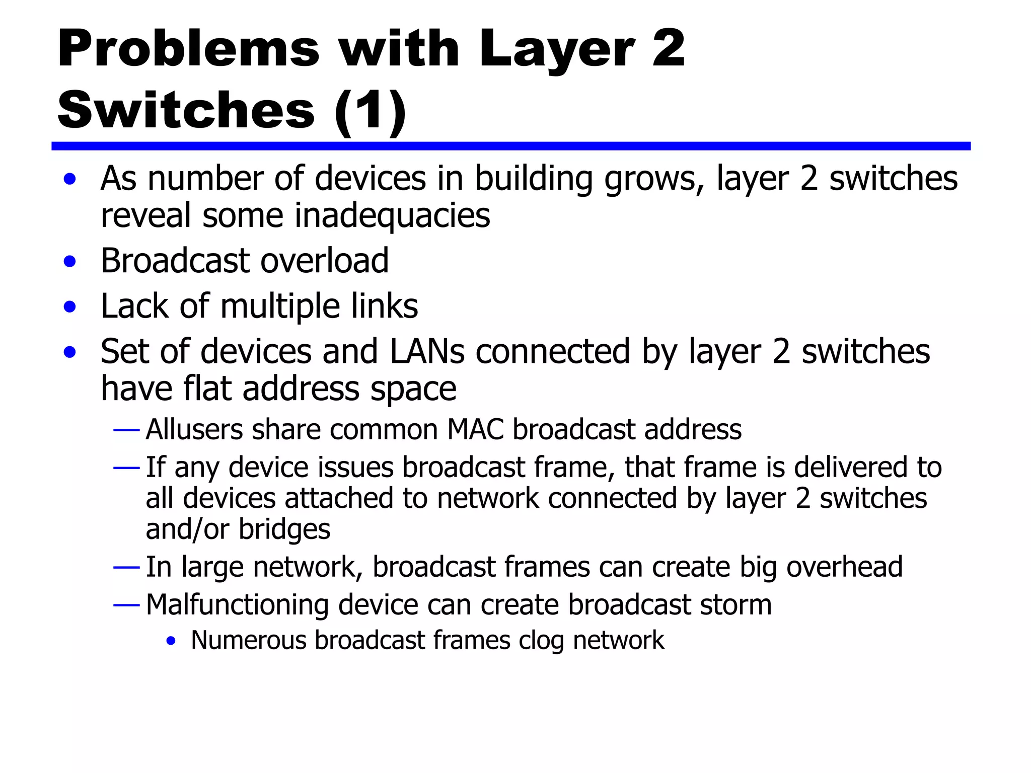
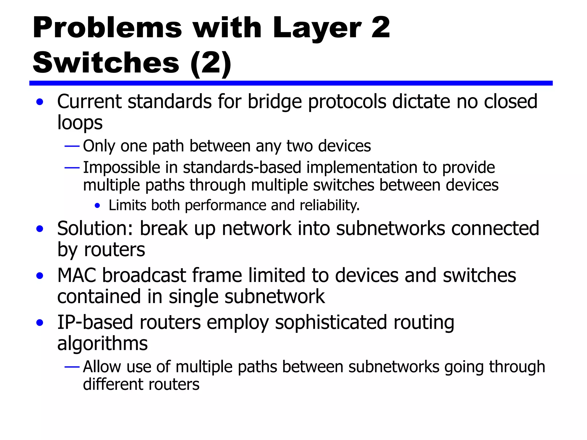
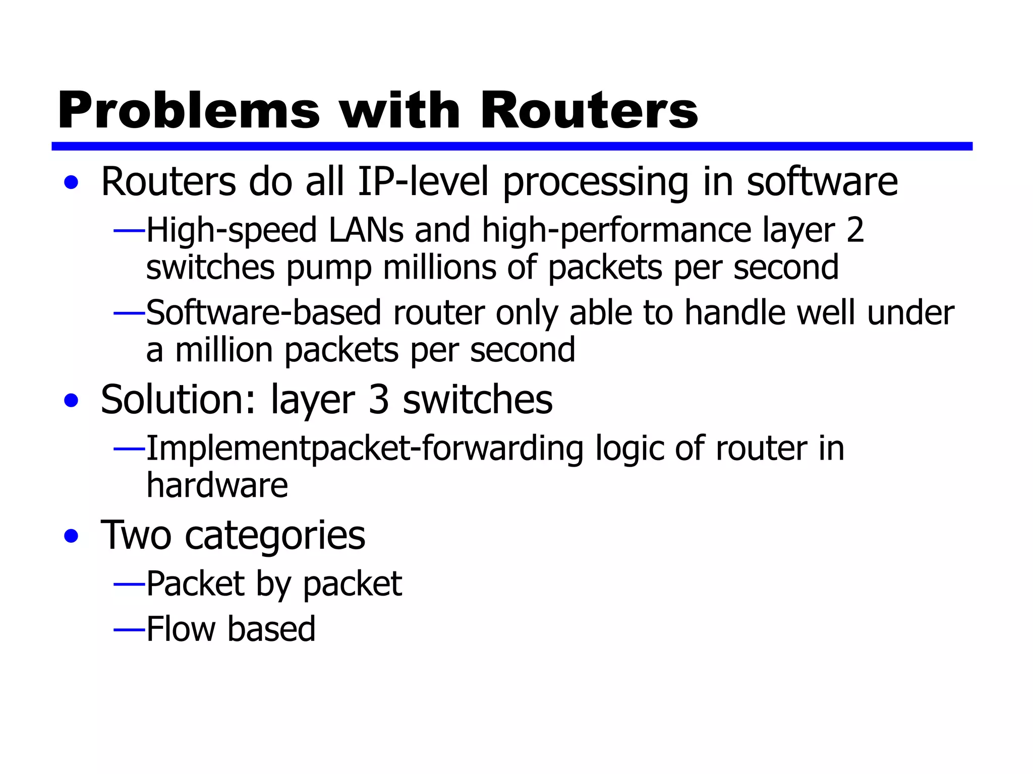
William Stallings
Data and Computer
Communications
7th Edition
Chapter 15
Local Area Network Overview
LAN Applications (1)
• Personal computer LANs
—Low cost
—Limited data rate
• Back end networks
—Interconnecting large systems (mainframes and large
storage devices)
• High data rate
• High speed interface
• Distributed access
• Limited distance
• Limited number of devices
LAN Applications (2)
• Storage Area Networks
— Separate network handling storage needs
— Detaches storage tasks from specific servers
— Shared storage facility across high-speed network
— Hard disks, tape libraries, CD arrays
— Improved client-server storage access
— Direct storage to storage communication for backup
• High speed office networks
— Desktop image processing
— High capacity local storage
• Backbone LANs
— Interconnect low speed local LANs
— Reliability
— Capacity
— Cost
Storage Area Networks
LAN Architecture
• Topologies
• Transmission medium
• Layout
• Medium access control
Topologies
• Tree
• Bus
—Special case of tree
• One trunk, no branches
• Ring
• Star
LAN Topologies
Bus and Tree
• Multipoint medium
• Transmission propagates throughout medium
• Heard by all stations
— Need to identify target station
• Each station has unique address
• Full duplex connection between station and tap
— Allows for transmission and reception
• Need to regulate transmission
— To avoid collisions
— To avoid hogging
• Data in small blocks - frames
• Terminator absorbs frames at end of medium
Frame
Transmission
on Bus LAN
Ring Topology
• Repeaters joined by point to point links in closed
loop
—Receive data on one link and retransmit on another
—Links unidirectional
—Stations attach to repeaters
• Data in frames
—Circulate past all stations
—Destination recognizes address and copies frame
—Frame circulates back to source where it is removed
• Media access control determines when station
can insert frame
Frame
Transmission
Ring LAN
Star Topology
• Each station connected directly to central node
—Usually via two point to point links
• Central node can broadcast
—Physical star, logical bus
—Only one station can transmit at a time
• Central node can act as frame switch
Choice of Topology
• Reliability
• Expandability
• Performance
• Needs considering in context of:
—Medium
—Wiring layout
—Access control
Bus LAN
Transmission Media (1)
• Twisted pair
—Early LANs used voice grade cable
—Didn’t scale for fast LANs
—Not used in bus LANs now
• Baseband coaxial cable
—Uses digital signalling
—Original Ethernet
Bus LAN
Transmission Media (2)
• Broadband coaxial cable
— As in cable TV systems
— Analog signals at radio frequencies
— Expensive, hard to install and maintain
— No longer used in LANs
• Optical fiber
— Expensive taps
— Better alternatives available
— Not used in bus LANs
• All hard to work with compared with star topology twisted pair
• Coaxial baseband still used but not often in new
installations
Ring and Star Usage
• Ring
—Very high speed links over long distances
—Single link or repeater failure disables network
• Star
—Uses natural layout of wiring in building
—Best for short distances
—High data rates for small number of devices
Choice of Medium
• Constrained by LAN topology
• Capacity
• Reliability
• Types of data supported
• Environmental scope
Media Available (1)
• Voice grade unshielded twisted pair (UTP)
—Cat 3
—Cheap
—Well understood
—Use existing telephone wiring in office building
—Low data rates
• Shielded twisted pair and baseband coaxial
—More expensive than UTP but higher data rates
• Broadband cable
—Still more expensive and higher data rate
Media Available (2)
• High performance UTP
— Cat 5 and above
— High data rate for small number of devices
— Switched star topology for large installations
• Optical fiber
— Electromagnetic isolation
— High capacity
— Small size
— High cost of components
— High skill needed to install and maintain
• Prices are coming down as demand and product range increases
Protocol Architecture
• Lower layers of OSI model
• IEEE 802 reference model
• Physical
• Logical link control (LLC)
• Media access control (MAC)
IEEE 802 v OSI
802 Layers -
Physical
• Encoding/decoding
• Preamble generation/removal
• Bit transmission/reception
• Transmission medium and topology
802 Layers -
Logical Link Control
• Interface to higher levels
• Flow and error control
Logical Link Control
• Transmission of link level PDUs between two
stations
• Must support multiaccess, shared medium
• Relieved of some link access details by MAC
layer
• Addressing involves specifying source and
destination LLC users
—Referred to as service access points (SAP)
—Typically higher level protocol
LLC Services
• Based on HDLC
• Unacknowledged connectionless service
• Connection mode service
• Acknowledged connectionless service
LLC Protocol
• Modeled after HDLC
• Asynchronous balanced mode to support
connection mode LLC service (type 2 operation)
• Unnumbered information PDUs to support
Acknowledged connectionless service (type 1)
• Multiplexing using LSAPs
Media Access Control
• Assembly of data into frame with address and
error detection fields
• Disassembly of frame
—Address recognition
—Error detection
• Govern access to transmission medium
—Not found in traditional layer 2 data link control
• For the same LLC, several MAC options may be
available
LAN Protocols in Context
Media Access Control
• Where
— Central
• Greater control
• Simple access logic at station
• Avoids problems of co-ordination
• Single point of failure
• Potential bottleneck
— Distributed
• How
— Synchronous
• Specific capacity dedicated to connection
— Asynchronous
• In response to demand
Asynchronous Systems
• Round robin
— Good if many stations have data to transmit over extended
period
• Reservation
— Good for stream traffic
• Contention
— Good for bursty traffic
— All stations contend for time
— Distributed
— Simple to implement
— Efficient under moderate load
— Tend to collapse under heavy load
MAC Frame Format
• MAC layer receives data from LLC layer
• MAC control
• Destination MAC address
• Source MAC address
• LLS
• CRC
• MAC layer detects errors and discards frames
• LLC optionally retransmits unsuccessful frames
Generic MAC Frame Format
Bridges
• Ability to expand beyond single LAN
• Provide interconnection to other LANs/WANs
• Use Bridge or router
• Bridge is simpler
—Connects similar LANs
—Identical protocols for physical and link layers
—Minimal processing
• Router more general purpose
—Interconnect various LANs and WANs
—see later
Why Bridge?
• Reliability
• Performance
• Security
• Geography
Functions of a Bridge
• Read all frames transmitted on one LAN and
accept those address to any station on the other
LAN
• Using MAC protocol for second LAN, retransmit
each frame
• Do the same the other way round
Bridge Operation
Bridge Design Aspects
• No modification to content or format of frame
• No encapsulation
• Exact bitwise copy of frame
• Minimal buffering to meet peak demand
• Contains routing and address intelligence
— Must be able to tell which frames to pass
— May be more than one bridge to cross
• May connect more than two LANs
• Bridging is transparent to stations
— Appears to all stations on multiple LANs as if they are on one
single LAN
Bridge Protocol Architecture
• IEEE 802.1D
• MAC level
— Station address is at this level
• Bridge does not need LLC layer
— It is relaying MAC frames
• Can pass frame over external comms system
— e.g. WAN link
— Capture frame
— Encapsulate it
— Forward it across link
— Remove encapsulation and forward over LAN link
Connection of Two LANs
Fixed Routing
• Complex large LANs need alternative routes
—Load balancing
—Fault tolerance
• Bridge must decide whether to forward frame
• Bridge must decide which LAN to forward frame
on
• Routing selected for each source-destination
pair of LANs
—Done in configuration
—Usually least hop route
—Only changed when topology changes
Bridges and
LANs with
Alternative
Routes
Spanning Tree
• Bridge automatically develops routing table
• Automatically update in response to changes
• Frame forwarding
• Address learning
• Loop resolution
Frame forwarding
• Maintain forwarding database for each port
—List station addresses reached through each port
• For a frame arriving on port X:
—Search forwarding database to see if MAC address is
listed for any port except X
—If address not found, forward to all ports except X
—If address listed for port Y, check port Y for blocking
or forwarding state
• Blocking prevents port from receiving or transmitting
—If not blocked, transmit frame through port Y
Address Learning
• Can preload forwarding database
• Can be learned
• When frame arrives at port X, it has come form
the LAN attached to port X
• Use the source address to update forwarding
database for port X to include that address
• Timer on each entry in database
• Each time frame arrives, source address
checked against forwarding database
Spanning Tree Algorithm
• Address learning works for tree layout
—i.e. no closed loops
• For any connected graph there is a spanning
tree that maintains connectivity but contains no
closed loops
• Each bridge assigned unique identifier
• Exchange between bridges to establish spanning
tree
Loop of Bridges
Layer 2 and Layer 3 Switches
• Now many types of devices for interconnecting
LANs
• Beyond bridges and routers
• Layer 2 switches
• Layer 3 switches
Hubs
• Active central element of star layout
• Each station connected to hub by two lines
— Transmit and receive
• Hub acts as a repeater
• When single station transmits, hub repeats signal on outgoing line
to each station
• Line consists of two unshielded twisted pairs
• Limited to about 100 m
— High data rate and poor transmission qualities of UTP
• Optical fiber may be used
— Max about 500 m
• Physically star, logically bus
• Transmission from any station received by all other stations
• If two stations transmit at the same time, collision
Hub Layouts
• Multiple levels of hubs cascaded
• Each hub may have a mixture of stations and other hubs
attached to from below
• Fits well with building wiring practices
— Wiring closet on each floor
— Hub can be placed in each one
— Each hub services stations on its floor
Two Level Star Topology
Buses and Hubs
• Bus configuration
—All stations share capacity of bus (e.g. 10Mbps)
—Only one station transmitting at a time
• Hub uses star wiring to attach stations to hub
—Transmission from any station received by hub and
retransmitted on all outgoing lines
—Only one station can transmit at a time
—Total capacity of LAN is 10 Mbps
• Improve performance with layer 2 switch
Shared Medium Bus and Hub
Shared Medium Hub and
Layer 2 Switch
Layer 2 Switches
• Central hub acts as switch
• Incoming frame from particular station switched
to appropriate output line
• Unused lines can switch other traffic
• More than one station transmitting at a time
• Multiplying capacity of LAN
Layer 2 Switch Benefits
• No change to attached devices to convert bus LAN or
hub LAN to switched LAN
• For Ethernet LAN, each device uses Ethernet MAC
protocol
• Device has dedicated capacity equal to original LAN
— Assuming switch has sufficient capacity to keep up with all
devices
— For example if switch can sustain throughput of 20 Mbps, each
device appears to have dedicated capacity for either input or
output of 10 Mbps
• Layer 2 switch scales easily
— Additional devices attached to switch by increasing capacity of
layer 2
Types of Layer 2 Switch
• Store-and-forward switch
— Accepts frame on input line
— Buffers it briefly,
— Then routes it to appropriate output line
— Delay between sender and receiver
— Boosts integrity of network
• Cut-through switch
— Takes advantage of destination address appearing at beginning
of frame
— Switch begins repeating frame onto output line as soon as it
recognizes destination address
— Highest possible throughput
— Risk of propagating bad frames
• Switch unable to check CRC prior to retransmission
Layer 2 Switch v Bridge
• Layer 2 switch can be viewed as full-duplex hub
• Can incorporate logic to function as multiport bridge
• Bridge frame handling done in software
• Switch performs address recognition and frame
forwarding in hardware
• Bridge only analyzes and forwards one frame at a time
• Switch has multiple parallel data paths
— Can handle multiple frames at a time
• Bridge uses store-and-forward operation
• Switch can have cut-through operation
• Bridge suffered commercially
— New installations typically include layer 2 switches with bridge
functionality rather than bridges
Problems with Layer 2
Switches (1)
• As number of devices in building grows, layer 2 switches
reveal some inadequacies
• Broadcast overload
• Lack of multiple links
• Set of devices and LANs connected by layer 2 switches
have flat address space
— Allusers share common MAC broadcast address
— If any device issues broadcast frame, that frame is delivered to
all devices attached to network connected by layer 2 switches
and/or bridges
— In large network, broadcast frames can create big overhead
— Malfunctioning device can create broadcast storm
• Numerous broadcast frames clog network
Problems with Layer 2
Switches (2)
• Current standards for bridge protocols dictate no closed
loops
— Only one path between any two devices
— Impossible in standards-based implementation to provide
multiple paths through multiple switches between devices
• Limits both performance and reliability.
• Solution: break up network into subnetworks connected
by routers
• MAC broadcast frame limited to devices and switches
contained in single subnetwork
• IP-based routers employ sophisticated routing
algorithms
— Allow use of multiple paths between subnetworks going through
different routers
Problems with Routers
• Routers do all IP-level processing in software
—High-speed LANs and high-performance layer 2
switches pump millions of packets per second
—Software-based router only able to handle well under
a million packets per second
• Solution: layer 3 switches
—Implementpacket-forwarding logic of router in
hardware
• Two categories
—Packet by packet
—Flow based
Packet by Packet or
Flow Based
• Operates insame way as traditional router
• Order of magnitude increase in performance
compared to software-based router
• Flow-based switch tries to enhance performance
by identifying flows of IP packets
—Same source and destination
—Done by observing ongoing traffic or using a special
flow label in packet header (IPv6)
—Once flow is identified, predefined route can be
established
Typical Large LAN Organization
• Thousands to tens of thousands of devices
• Desktop systems links 10 Mbps to 100 Mbps
— Into layer 2 switch
• Wireless LAN connectivity available for mobile users
• Layer 3 switches at local network's core
— Form local backbone
— Interconnected at 1 Gbps
— Connect to layer 2 switches at 100 Mbps to 1 Gbps
• Servers connect directly to layer 2 or layer 3 switches at
1 Gbps
• Lower-cost software-based router provides WAN
connection
• Circles in diagram identify separate LAN subnetworks
• MAC broadcast frame limited to own subnetwork
Typical
Large
LAN
Organization
Diagram
Required Reading
• Stallings chapter 15
• Loads of info on the Web

CS553_ST7_Ch15-LANOverview.ppt

  • 1.
    William Stallings Data andComputer Communications 7th Edition Chapter 15 Local Area Network Overview
  • 2.
    LAN Applications (1) •Personal computer LANs —Low cost —Limited data rate • Back end networks —Interconnecting large systems (mainframes and large storage devices) • High data rate • High speed interface • Distributed access • Limited distance • Limited number of devices
  • 3.
    LAN Applications (2) •Storage Area Networks — Separate network handling storage needs — Detaches storage tasks from specific servers — Shared storage facility across high-speed network — Hard disks, tape libraries, CD arrays — Improved client-server storage access — Direct storage to storage communication for backup • High speed office networks — Desktop image processing — High capacity local storage • Backbone LANs — Interconnect low speed local LANs — Reliability — Capacity — Cost
  • 4.
  • 5.
    LAN Architecture • Topologies •Transmission medium • Layout • Medium access control
  • 6.
    Topologies • Tree • Bus —Specialcase of tree • One trunk, no branches • Ring • Star
  • 7.
  • 8.
    Bus and Tree •Multipoint medium • Transmission propagates throughout medium • Heard by all stations — Need to identify target station • Each station has unique address • Full duplex connection between station and tap — Allows for transmission and reception • Need to regulate transmission — To avoid collisions — To avoid hogging • Data in small blocks - frames • Terminator absorbs frames at end of medium
  • 9.
  • 10.
    Ring Topology • Repeatersjoined by point to point links in closed loop —Receive data on one link and retransmit on another —Links unidirectional —Stations attach to repeaters • Data in frames —Circulate past all stations —Destination recognizes address and copies frame —Frame circulates back to source where it is removed • Media access control determines when station can insert frame
  • 11.
  • 12.
    Star Topology • Eachstation connected directly to central node —Usually via two point to point links • Central node can broadcast —Physical star, logical bus —Only one station can transmit at a time • Central node can act as frame switch
  • 13.
    Choice of Topology •Reliability • Expandability • Performance • Needs considering in context of: —Medium —Wiring layout —Access control
  • 14.
    Bus LAN Transmission Media(1) • Twisted pair —Early LANs used voice grade cable —Didn’t scale for fast LANs —Not used in bus LANs now • Baseband coaxial cable —Uses digital signalling —Original Ethernet
  • 15.
    Bus LAN Transmission Media(2) • Broadband coaxial cable — As in cable TV systems — Analog signals at radio frequencies — Expensive, hard to install and maintain — No longer used in LANs • Optical fiber — Expensive taps — Better alternatives available — Not used in bus LANs • All hard to work with compared with star topology twisted pair • Coaxial baseband still used but not often in new installations
  • 16.
    Ring and StarUsage • Ring —Very high speed links over long distances —Single link or repeater failure disables network • Star —Uses natural layout of wiring in building —Best for short distances —High data rates for small number of devices
  • 17.
    Choice of Medium •Constrained by LAN topology • Capacity • Reliability • Types of data supported • Environmental scope
  • 18.
    Media Available (1) •Voice grade unshielded twisted pair (UTP) —Cat 3 —Cheap —Well understood —Use existing telephone wiring in office building —Low data rates • Shielded twisted pair and baseband coaxial —More expensive than UTP but higher data rates • Broadband cable —Still more expensive and higher data rate
  • 19.
    Media Available (2) •High performance UTP — Cat 5 and above — High data rate for small number of devices — Switched star topology for large installations • Optical fiber — Electromagnetic isolation — High capacity — Small size — High cost of components — High skill needed to install and maintain • Prices are coming down as demand and product range increases
  • 20.
    Protocol Architecture • Lowerlayers of OSI model • IEEE 802 reference model • Physical • Logical link control (LLC) • Media access control (MAC)
  • 21.
  • 22.
    802 Layers - Physical •Encoding/decoding • Preamble generation/removal • Bit transmission/reception • Transmission medium and topology
  • 23.
    802 Layers - LogicalLink Control • Interface to higher levels • Flow and error control
  • 24.
    Logical Link Control •Transmission of link level PDUs between two stations • Must support multiaccess, shared medium • Relieved of some link access details by MAC layer • Addressing involves specifying source and destination LLC users —Referred to as service access points (SAP) —Typically higher level protocol
  • 25.
    LLC Services • Basedon HDLC • Unacknowledged connectionless service • Connection mode service • Acknowledged connectionless service
  • 26.
    LLC Protocol • Modeledafter HDLC • Asynchronous balanced mode to support connection mode LLC service (type 2 operation) • Unnumbered information PDUs to support Acknowledged connectionless service (type 1) • Multiplexing using LSAPs
  • 27.
    Media Access Control •Assembly of data into frame with address and error detection fields • Disassembly of frame —Address recognition —Error detection • Govern access to transmission medium —Not found in traditional layer 2 data link control • For the same LLC, several MAC options may be available
  • 28.
  • 29.
    Media Access Control •Where — Central • Greater control • Simple access logic at station • Avoids problems of co-ordination • Single point of failure • Potential bottleneck — Distributed • How — Synchronous • Specific capacity dedicated to connection — Asynchronous • In response to demand
  • 30.
    Asynchronous Systems • Roundrobin — Good if many stations have data to transmit over extended period • Reservation — Good for stream traffic • Contention — Good for bursty traffic — All stations contend for time — Distributed — Simple to implement — Efficient under moderate load — Tend to collapse under heavy load
  • 31.
    MAC Frame Format •MAC layer receives data from LLC layer • MAC control • Destination MAC address • Source MAC address • LLS • CRC • MAC layer detects errors and discards frames • LLC optionally retransmits unsuccessful frames
  • 32.
  • 33.
    Bridges • Ability toexpand beyond single LAN • Provide interconnection to other LANs/WANs • Use Bridge or router • Bridge is simpler —Connects similar LANs —Identical protocols for physical and link layers —Minimal processing • Router more general purpose —Interconnect various LANs and WANs —see later
  • 34.
    Why Bridge? • Reliability •Performance • Security • Geography
  • 35.
    Functions of aBridge • Read all frames transmitted on one LAN and accept those address to any station on the other LAN • Using MAC protocol for second LAN, retransmit each frame • Do the same the other way round
  • 36.
  • 37.
    Bridge Design Aspects •No modification to content or format of frame • No encapsulation • Exact bitwise copy of frame • Minimal buffering to meet peak demand • Contains routing and address intelligence — Must be able to tell which frames to pass — May be more than one bridge to cross • May connect more than two LANs • Bridging is transparent to stations — Appears to all stations on multiple LANs as if they are on one single LAN
  • 38.
    Bridge Protocol Architecture •IEEE 802.1D • MAC level — Station address is at this level • Bridge does not need LLC layer — It is relaying MAC frames • Can pass frame over external comms system — e.g. WAN link — Capture frame — Encapsulate it — Forward it across link — Remove encapsulation and forward over LAN link
  • 39.
  • 40.
    Fixed Routing • Complexlarge LANs need alternative routes —Load balancing —Fault tolerance • Bridge must decide whether to forward frame • Bridge must decide which LAN to forward frame on • Routing selected for each source-destination pair of LANs —Done in configuration —Usually least hop route —Only changed when topology changes
  • 41.
  • 42.
    Spanning Tree • Bridgeautomatically develops routing table • Automatically update in response to changes • Frame forwarding • Address learning • Loop resolution
  • 43.
    Frame forwarding • Maintainforwarding database for each port —List station addresses reached through each port • For a frame arriving on port X: —Search forwarding database to see if MAC address is listed for any port except X —If address not found, forward to all ports except X —If address listed for port Y, check port Y for blocking or forwarding state • Blocking prevents port from receiving or transmitting —If not blocked, transmit frame through port Y
  • 44.
    Address Learning • Canpreload forwarding database • Can be learned • When frame arrives at port X, it has come form the LAN attached to port X • Use the source address to update forwarding database for port X to include that address • Timer on each entry in database • Each time frame arrives, source address checked against forwarding database
  • 45.
    Spanning Tree Algorithm •Address learning works for tree layout —i.e. no closed loops • For any connected graph there is a spanning tree that maintains connectivity but contains no closed loops • Each bridge assigned unique identifier • Exchange between bridges to establish spanning tree
  • 46.
  • 47.
    Layer 2 andLayer 3 Switches • Now many types of devices for interconnecting LANs • Beyond bridges and routers • Layer 2 switches • Layer 3 switches
  • 48.
    Hubs • Active centralelement of star layout • Each station connected to hub by two lines — Transmit and receive • Hub acts as a repeater • When single station transmits, hub repeats signal on outgoing line to each station • Line consists of two unshielded twisted pairs • Limited to about 100 m — High data rate and poor transmission qualities of UTP • Optical fiber may be used — Max about 500 m • Physically star, logically bus • Transmission from any station received by all other stations • If two stations transmit at the same time, collision
  • 49.
    Hub Layouts • Multiplelevels of hubs cascaded • Each hub may have a mixture of stations and other hubs attached to from below • Fits well with building wiring practices — Wiring closet on each floor — Hub can be placed in each one — Each hub services stations on its floor
  • 50.
  • 51.
    Buses and Hubs •Bus configuration —All stations share capacity of bus (e.g. 10Mbps) —Only one station transmitting at a time • Hub uses star wiring to attach stations to hub —Transmission from any station received by hub and retransmitted on all outgoing lines —Only one station can transmit at a time —Total capacity of LAN is 10 Mbps • Improve performance with layer 2 switch
  • 52.
  • 53.
    Shared Medium Huband Layer 2 Switch
  • 54.
    Layer 2 Switches •Central hub acts as switch • Incoming frame from particular station switched to appropriate output line • Unused lines can switch other traffic • More than one station transmitting at a time • Multiplying capacity of LAN
  • 55.
    Layer 2 SwitchBenefits • No change to attached devices to convert bus LAN or hub LAN to switched LAN • For Ethernet LAN, each device uses Ethernet MAC protocol • Device has dedicated capacity equal to original LAN — Assuming switch has sufficient capacity to keep up with all devices — For example if switch can sustain throughput of 20 Mbps, each device appears to have dedicated capacity for either input or output of 10 Mbps • Layer 2 switch scales easily — Additional devices attached to switch by increasing capacity of layer 2
  • 56.
    Types of Layer2 Switch • Store-and-forward switch — Accepts frame on input line — Buffers it briefly, — Then routes it to appropriate output line — Delay between sender and receiver — Boosts integrity of network • Cut-through switch — Takes advantage of destination address appearing at beginning of frame — Switch begins repeating frame onto output line as soon as it recognizes destination address — Highest possible throughput — Risk of propagating bad frames • Switch unable to check CRC prior to retransmission
  • 57.
    Layer 2 Switchv Bridge • Layer 2 switch can be viewed as full-duplex hub • Can incorporate logic to function as multiport bridge • Bridge frame handling done in software • Switch performs address recognition and frame forwarding in hardware • Bridge only analyzes and forwards one frame at a time • Switch has multiple parallel data paths — Can handle multiple frames at a time • Bridge uses store-and-forward operation • Switch can have cut-through operation • Bridge suffered commercially — New installations typically include layer 2 switches with bridge functionality rather than bridges
  • 58.
    Problems with Layer2 Switches (1) • As number of devices in building grows, layer 2 switches reveal some inadequacies • Broadcast overload • Lack of multiple links • Set of devices and LANs connected by layer 2 switches have flat address space — Allusers share common MAC broadcast address — If any device issues broadcast frame, that frame is delivered to all devices attached to network connected by layer 2 switches and/or bridges — In large network, broadcast frames can create big overhead — Malfunctioning device can create broadcast storm • Numerous broadcast frames clog network
  • 59.
    Problems with Layer2 Switches (2) • Current standards for bridge protocols dictate no closed loops — Only one path between any two devices — Impossible in standards-based implementation to provide multiple paths through multiple switches between devices • Limits both performance and reliability. • Solution: break up network into subnetworks connected by routers • MAC broadcast frame limited to devices and switches contained in single subnetwork • IP-based routers employ sophisticated routing algorithms — Allow use of multiple paths between subnetworks going through different routers
  • 60.
    Problems with Routers •Routers do all IP-level processing in software —High-speed LANs and high-performance layer 2 switches pump millions of packets per second —Software-based router only able to handle well under a million packets per second • Solution: layer 3 switches —Implementpacket-forwarding logic of router in hardware • Two categories —Packet by packet —Flow based
  • 61.
    Packet by Packetor Flow Based • Operates insame way as traditional router • Order of magnitude increase in performance compared to software-based router • Flow-based switch tries to enhance performance by identifying flows of IP packets —Same source and destination —Done by observing ongoing traffic or using a special flow label in packet header (IPv6) —Once flow is identified, predefined route can be established
  • 62.
    Typical Large LANOrganization • Thousands to tens of thousands of devices • Desktop systems links 10 Mbps to 100 Mbps — Into layer 2 switch • Wireless LAN connectivity available for mobile users • Layer 3 switches at local network's core — Form local backbone — Interconnected at 1 Gbps — Connect to layer 2 switches at 100 Mbps to 1 Gbps • Servers connect directly to layer 2 or layer 3 switches at 1 Gbps • Lower-cost software-based router provides WAN connection • Circles in diagram identify separate LAN subnetworks • MAC broadcast frame limited to own subnetwork
  • 63.
  • 64.
    Required Reading • Stallingschapter 15 • Loads of info on the Web