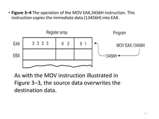
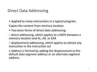
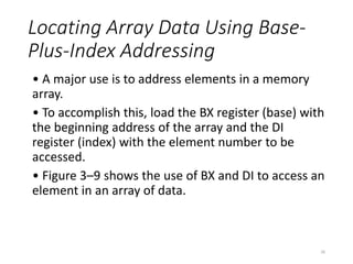
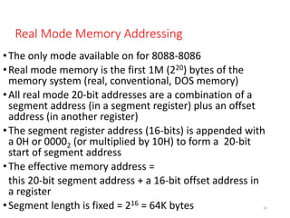
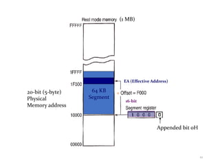
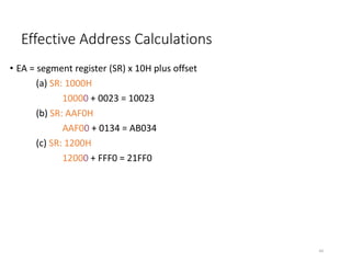
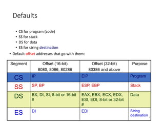
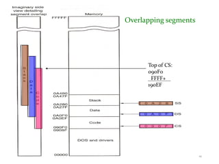
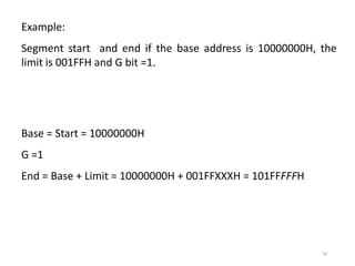
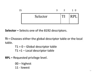
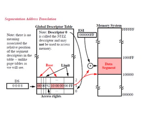
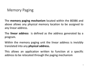
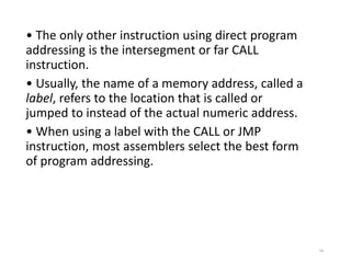
This document discusses different memory addressing modes used in microprocessors, including real mode, protected mode, and flat mode addressing. It provides details on how addresses are calculated in real mode using segment registers and offsets. Protected mode addressing allows accessing memory above 1MB by using descriptor tables to map segment selectors to base addresses and limits. Various programming models for addressing program memory and stack memory are also covered.

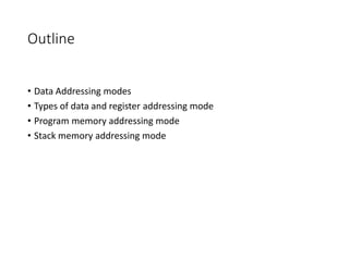
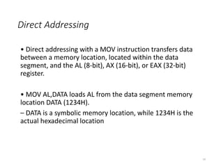
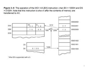
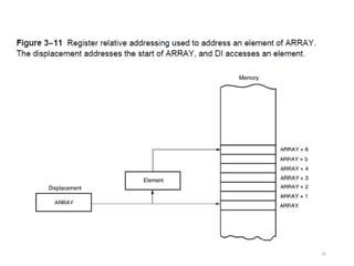
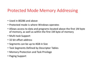
![Register Relative Addressing
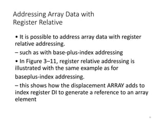
• Similar to base-plus-index addressing and
displacement addressing.
– data in a segment of memory are addressed by
adding the displacement to the contents of a base
or an index register (BP, BX, DI, or SI)
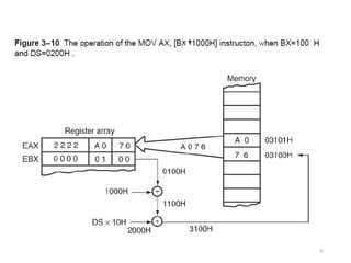
• Figure 3–10 shows the operation of the
MOV AX,[BX+1000H] instruction.
• A real mode segment is 64K bytes long.
28](https://image.slidesharecdn.com/lect03-mitaddressingmodes-230429170531-afc08c2a/85/lect-03-MIT-Addressing-Modes-pdf-28-320.jpg)
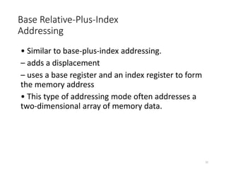
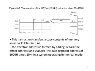
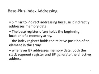
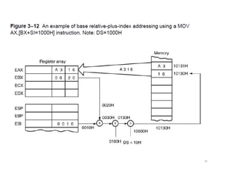
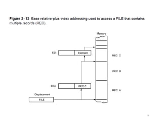
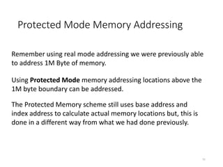
![Addressing Data with Base
Relative-Plus-Index
• Least-used addressing mode.
• Figure 3–12 shows how data are referenced if the
instruction executed by the microprocessor is MOV
AX,[BX + SI + 100H].
– displacement of 100H adds to BX and SI to form
the offset address within the data segment
• This addressing mode is too complex for frequent
use in programming.
33](https://image.slidesharecdn.com/lect03-mitaddressingmodes-230429170531-afc08c2a/85/lect-03-MIT-Addressing-Modes-pdf-33-320.jpg)
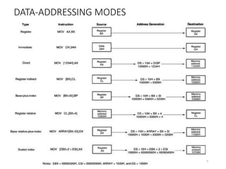
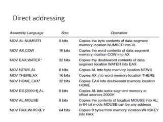
![Scaled-Index Addressing
• Unique to 80386 - Core2 microprocessors.
– uses two 32-bit registers (a base register and an
index register) to access the memory
• The second register (index) is multiplied by a
scaling factor.
– the scaling factor can be 1x, 2x, 4x, 8x
• A scaling factor of is implied and need not be
included in the assembly language instruction
(MOV AL,[EBX + ECX]).
37](https://image.slidesharecdn.com/lect03-mitaddressingmodes-230429170531-afc08c2a/85/lect-03-MIT-Addressing-Modes-pdf-37-320.jpg)
![Task
• MOV [7000H],CX
• Which addressing does instruction above belong, and why?](https://image.slidesharecdn.com/lect03-mitaddressingmodes-230429170531-afc08c2a/85/lect-03-MIT-Addressing-Modes-pdf-38-320.jpg)
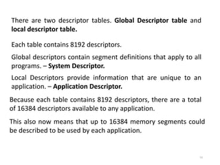
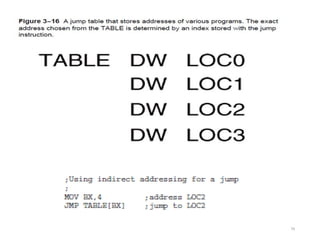
![• If a relative register holds the address, the
jump is considered to be an indirect jump.
• For example, JMP [BX] refers to the memory
location within the data segment at the offset
address contained in BX.
– at this offset address is a 16-bit number used as
the offset address in the intra-segment jump
– this type of jump is sometimes called an indirect-
indirect or double-indirect jump
• Figure shows a jump table that is stored,
beginning at memory location TABLE.
78](https://image.slidesharecdn.com/lect03-mitaddressingmodes-230429170531-afc08c2a/85/lect-03-MIT-Addressing-Modes-pdf-78-320.jpg)