Contents:-
• Analog CommunicationSchemes– Modern
communication system scheme, Information source,
and input transducer, Transmitter, Channel or Medium –
Hardwired and Soft wired, Noise, Receiver, Multiplexing,
Types of communication systems. Types of modulation
(only concepts)– AM , FM, Phase Modulation, Concept
of Radio wave propagation (Ground, space, sky ).
• Digital Modulation Schemes –Advantages of digital
communication over analog communication , ASK, FSK,
PSK, Radio signal transmission ,Multiple access
techniques.
3.
Analog Communication Schemes
5.1MODERN COMMUNICATION SYSTEM SCHEME:-
• Communication engineering deals with the techniques of
transmitting information.
• Communication engineering means electrical communication,
in which information is transmitted through electrical signals.
• Electrical communication is a process by which the
information message is transmitted from one point to
another, from one person to another, or from one place to
another in the form of electrical signals, through some
communication link.
• Basic communication system provides a link between the
information source and its destination. The process of
electrical communication involves sending, receiving, and
processing information in electrical form.
4.
• The informationto be transmitted passes through a
number of stages of the communication system
prior it reaches its destination.
• Figure 5.1 shows a block schematic diagram of the
most general form of basic communication system.
Fig-5.1: Schematic diagram of the most general form of basic
communication system
5.
The main constituentsof basic communication system are:
• Information source and input transducer
• Transmitter
• Channel or medium
• Noise
• Receiver
• Output transducer and final destination.
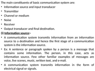
(i) Information source:-
• A communication system transmits information from an information
source to a destination and hence the first stage of a communication
system is the information source.
• Ex: A sentence or paragraph spoken by a person is a message that
contains some information. The person, in this case, acts as
information source. Few other familiar examples of messages are
voice, live scenes, music, written text, and e-mail.
• A communication system transmits information in the form of
electrical signal or signals.
6.
(ii) Input transducer:-
•A transducer is a device that converts a non-electrical energy into
its corresponding electrical energy called signal and vice versa, e.g.,
during a telephone conversation, the words spoken by a person are
in the form of sound energy.
• An example of a transducer is a microphone. Microphone converts
sound signals into the corresponding electrical signals.
• Similarly, a television (TV) picture tube converts electrical signals
into its corresponding pictures. Some other examples of
transducers are movie cameras, Video Cassette, Recorder (VCR)
heads, tape recorder heads, and loudspeakers.
• The information produced by the information source is applied to
the next stage, termed the information or input /transducer. This in
turn, produces an electrical signal corresponding to the information
as output. This electrical signal is called the baseband signal. It is
also called a message signal s(t).
7.
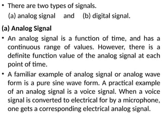
• There aretwo types of signals.
(a) analog signal and (b) digital signal.
(a) Analog Signal
• An analog signal is a function of time, and has a
continuous range of values. However, there is a
definite function value of the analog signal at each
point of time.
• A familiar example of analog signal or analog wave
form is a pure sine wave form. A practical example
of an analog signal is a voice signal. When a voice
signal is converted to electrical for by a microphone,
one gets a corresponding electrical analog signal.
8.
.
(b) Digital signal
Adigital signal does not have continuous function values on a
time scale. It is discrete in nature, i.e., it has some values at
discrete timings.
A familiar example of a digital signal is the sound signal
produced by drumbeats.
Fig 5.3: Digital signal
9.
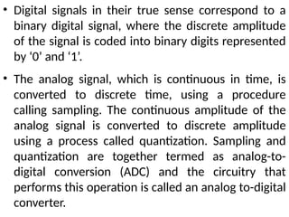
• Digital signalsin their true sense correspond to a
binary digital signal, where the discrete amplitude
of the signal is coded into binary digits represented
by ‘0’ and ‘1’.
• The analog signal, which is continuous in time, is
converted to discrete time, using a procedure
calling sampling. The continuous amplitude of the
analog signal is converted to discrete amplitude
using a process called quantization. Sampling and
quantization are together termed as analog-to-
digital conversion (ADC) and the circuitry that
performs this operation is called an analog to-digital
converter.
10.
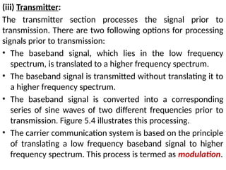
(iii) Transmitter:
The transmittersection processes the signal prior to
transmission. There are two following options for processing
signals prior to transmission:
• The baseband signal, which lies in the low frequency
spectrum, is translated to a higher frequency spectrum.
• The baseband signal is transmitted without translating it to
a higher frequency spectrum.
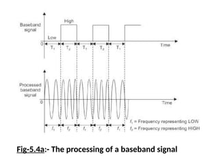
• The baseband signal is converted into a corresponding
series of sine waves of two different frequencies prior to
transmission. Figure 5.4 illustrates this processing.
• The carrier communication system is based on the principle
of translating a low frequency baseband signal to higher
frequency spectrum. This process is termed as modulation.
11.
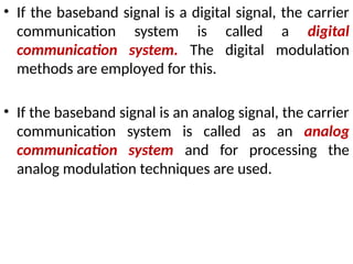
• If thebaseband signal is a digital signal, the carrier
communication system is called a digital
communication system. The digital modulation
methods are employed for this.
• If the baseband signal is an analog signal, the carrier
communication system is called as an analog
communication system and for processing the
analog modulation techniques are used.
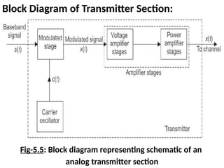
Block Diagram ofTransmitter Section:
Fig-5.5: Block diagram representing schematic of an
analog transmitter section
15.
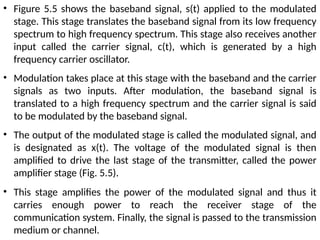
• Figure 5.5shows the baseband signal, s(t) applied to the modulated
stage. This stage translates the baseband signal from its low frequency
spectrum to high frequency spectrum. This stage also receives another
input called the carrier signal, c(t), which is generated by a high
frequency carrier oscillator.
• Modulation takes place at this stage with the baseband and the carrier
signals as two inputs. After modulation, the baseband signal is
translated to a high frequency spectrum and the carrier signal is said
to be modulated by the baseband signal.
• The output of the modulated stage is called the modulated signal, and
is designated as x(t). The voltage of the modulated signal is then
amplified to drive the last stage of the transmitter, called the power
amplifier stage (Fig. 5.5).
• This stage amplifies the power of the modulated signal and thus it
carries enough power to reach the receiver stage of the
communication system. Finally, the signal is passed to the transmission
medium or channel.
16.
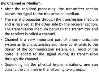
(iv) Channel orMedium:
• After the required processing, the transmitter section
passes the signal to the transmission medium.
• The signal propagates through the transmission medium
and is received at the other side by the receiver section.
The transmission medium between the transmitter and
the receiver is called a channel.
• Channel is a very important part of a communication
system as its characteristics add many constraints to the
design of the communication system, e.g., most of the
noise is added to the signal during its transmission
through the channel.
• Depending on the physical implementations, one can
classify the channels in the following two groups:
17.
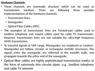
Hardware Channels:
• Thesechannels are manmade structure which can be used as
transmission medium. There are following three possible
implementations of the hardware channels.
– Transmission lines
– Waveguides
– Optical Fiber Cables (OFC)
• The examples of transmission lines are Twisted-pair cables used in
landline telephony and coaxial cables used for cable TV transmission.
However, transmission lines are not suitable for ultra-high frequency
(UHF) transmission.
• To transmit signals at UHF range, Waveguides are employed as medium.
Waveguides are hollow, circular, or rectangular metallic structures. The
signals enter the waveguide, are reflected at the metallic walls, and
propagate towards the other end of the waveguide.
• Optical fiber cables are highly sophisticated transmission media, in
the form of extremely thin circular pipes. e.g., landline telephony
and cable TV network.
18.
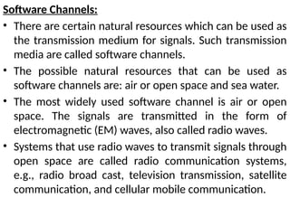
Software Channels:
• Thereare certain natural resources which can be used as
the transmission medium for signals. Such transmission
media are called software channels.
• The possible natural resources that can be used as
software channels are: air or open space and sea water.
• The most widely used software channel is air or open
space. The signals are transmitted in the form of
electromagnetic (EM) waves, also called radio waves.
• Systems that use radio waves to transmit signals through
open space are called radio communication systems,
e.g., radio broad cast, television transmission, satellite
communication, and cellular mobile communication.
19.
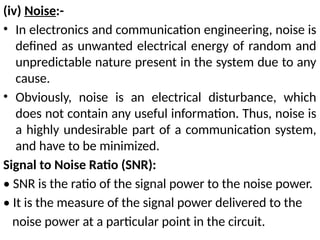
(iv) Noise:-
• Inelectronics and communication engineering, noise is
defined as unwanted electrical energy of random and
unpredictable nature present in the system due to any
cause.
• Obviously, noise is an electrical disturbance, which
does not contain any useful information. Thus, noise is
a highly undesirable part of a communication system,
and have to be minimized.
Signal to Noise Ratio (SNR):
• SNR is the ratio of the signal power to the noise power.
• It is the measure of the signal power delivered to the
noise power at a particular point in the circuit.
20.
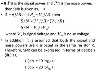
• If isthe signal power and is the noise power,
𝑃𝑠 𝑃𝑛
then SNR is given as, = .
• If = Vs
2
/ and
𝑅 𝑃𝑛 = 𝑉𝑛
2
/ , then
𝑅
𝑆/ = (
𝑁 𝑉𝑠
2
/ )*(
𝑅 𝑉𝑛
2
/ )
𝑅
𝑆/ =
𝑁 𝑉𝑠
2
/𝑉𝑛
2
where 𝑉𝑠 is signal voltage and 𝑉𝑛 is noise voltage.
• In addition, it is assumed that both the signal and
noise powers are dissipated in the same resistor R.
Therefore, SNR can be expressed in terms of decibels
(dB) as,
( )db = 10 log10 ()
( )db = 20 log10 ()
21.
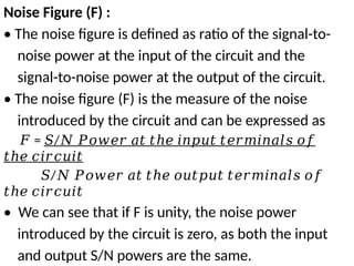
Noise Figure (F):
• The noise figure is defined as ratio of the signal-to-
noise power at the input of the circuit and the
signal-to-noise power at the output of the circuit.
• The noise figure (F) is the measure of the noise
introduced by the circuit and can be expressed as
𝐹 = /
𝑆 𝑁 𝑃𝑜𝑤𝑒𝑟 𝑎𝑡 𝑡ℎ𝑒 𝑖𝑛𝑝𝑢𝑡 𝑡𝑒𝑟𝑚𝑖𝑛𝑎𝑙𝑠 𝑜𝑓
𝑡ℎ𝑒 𝑐𝑖𝑟𝑐𝑢𝑖𝑡
𝑆/𝑁 𝑃𝑜𝑤𝑒𝑟 𝑎𝑡 𝑡ℎ𝑒 𝑜𝑢𝑡𝑝𝑢𝑡 𝑡𝑒𝑟𝑚𝑖𝑛𝑎𝑙𝑠 𝑜𝑓
𝑡ℎ𝑒 𝑐𝑖𝑟𝑐𝑢𝑖𝑡
• We can see that if F is unity, the noise power
introduced by the circuit is zero, as both the input
and output S/N powers are the same.
22.
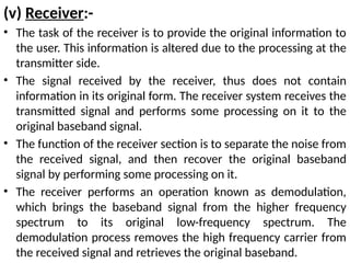
(v) Receiver:-
• Thetask of the receiver is to provide the original information to
the user. This information is altered due to the processing at the
transmitter side.
• The signal received by the receiver, thus does not contain
information in its original form. The receiver system receives the
transmitted signal and performs some processing on it to the
original baseband signal.
• The function of the receiver section is to separate the noise from
the received signal, and then recover the original baseband
signal by performing some processing on it.
• The receiver performs an operation known as demodulation,
which brings the baseband signal from the higher frequency
spectrum to its original low-frequency spectrum. The
demodulation process removes the high frequency carrier from
the received signal and retrieves the original baseband.
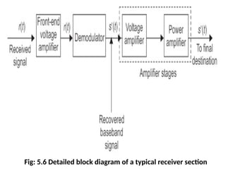
• From Fig.5.6 it is evident that the received signal, r(t), is
first amplified by the front- end voltage amplifier. This is
done to strengthen the received signal, which is weak and
to facilitate easy processing.
• Next, this signal is given to the demodulator, which in turn,
demodulates the received signal to recover the original
baseband signal. After recovering the original baseband
signal, its voltage and power is amplified prior it to final
destination block.
Destination:
• Destination is the final stage which is used to convert an
electrical message signal into its original form. For example
in radio broadcasting, the destination is a loud speaker
which works as a transducer that converts the electrical
signal to original sound signal.
25.
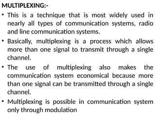
MULTIPLEXING:-
• This isa technique that is most widely used in
nearly all types of communication systems, radio
and line communication systems.
• Basically, multiplexing is a process which allows
more than one signal to transmit through a single
channel.
• The use of multiplexing also makes the
communication system economical because more
than one signal can be transmitted through a single
channel.
• Multiplexing is possible in communication system
only through modulation
27.
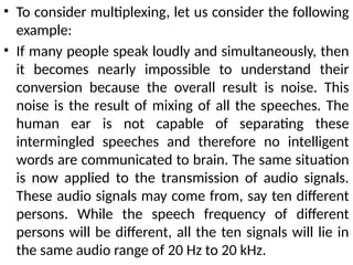
• To considermultiplexing, let us consider the following
example:
• If many people speak loudly and simultaneously, then
it becomes nearly impossible to understand their
conversion because the overall result is noise. This
noise is the result of mixing of all the speeches. The
human ear is not capable of separating these
intermingled speeches and therefore no intelligent
words are communicated to brain. The same situation
is now applied to the transmission of audio signals.
These audio signals may come from, say ten different
persons. While the speech frequency of different
persons will be different, all the ten signals will lie in
the same audio range of 20 Hz to 20 kHz.
28.
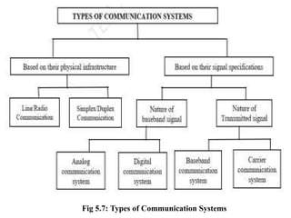
TYPES OF COMMUNICATIONSYSTEMS:-
One may categorize communication systems based
on:
• The physical infrastructure pertains to the type of
the channel used and the hardware design of the
transmitting and receiving equipment.
• The signal specifications signify the nature and type
of the transmitted signal
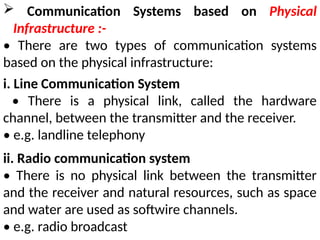
Communication Systemsbased on Physical
Infrastructure :-
• There are two types of communication systems
based on the physical infrastructure:
i. Line Communication System
• There is a physical link, called the hardware
channel, between the transmitter and the receiver.
• e.g. landline telephony
ii. Radio communication system
• There is no physical link between the transmitter
and the receiver and natural resources, such as space
and water are used as softwire channels.
• e.g. radio broadcast
31.
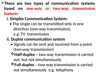
There are twotypes of communication systems
based on one-way or two-way transmission
feature:-
i. Simplex Communication System:
• The single can be transmitted only in one
direction (one-way transmission).
e.g. TV transmission
ii. Duplex communication system
• Signals can be sent and received from a point.
(two-way transmission)
Half-duplex – two-way transmission is carried
out, but not simultaneously
Full-duplex – two-way transmission is carried
out simultaneously e.g. telephony
33.
Communication Systems basedon Signal
Specifications :
• There are two types of communication systems
based on the nature of baseband signal:
i. Analog Communication System • e.g. TV transmission
ii. Digital communication system • e.g. HDTV, Internet
There are two types of communication systems
based on the nature of transmitted signal:
i. Baseband Communication System • e.g. landline
telephony, fax
ii. Carrier communication system • e.g. TV
34.
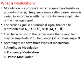
What is Modulation?
•Modulation is a process in which some characteristic or
property of a high frequency signal called carrier signal is
varied in accordance with the instantaneous amplitude
of the message signal.
• The carrier signal is a sinusoidal signal that can be
represented as 𝒗𝒄 ( ) =
𝒕 𝑽𝒄 (
𝐬𝐢𝐧 𝝎𝒄 + )
𝒕 𝜽
• The characteristic of the carrier wave that is modified
may be amplitude , frequency or phase angle .
𝑉𝑐 𝑓𝑐 𝜃
• Accordingly, we have three types of modulation:
i. Amplitude Modulation
ii. Frequency Modulation
iii. Phase Modulation
35.
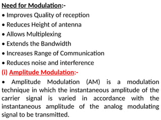
Need for Modulation:-
•Improves Quality of reception
• Reduces Height of antenna
• Allows Multiplexing
• Extends the Bandwidth
• Increases Range of Communication
• Reduces noise and interference
(i) Amplitude Modulation:-
• Amplitude Modulation (AM) is a modulation
technique in which the instantaneous amplitude of the
carrier signal is varied in accordance with the
instantaneous amplitude of the analog modulating
signal to be transmitted.
36.
• The amplitudeof the carrier
wave is varied in accordance
with the modulating signal
while the frequency and
phase of the carrier signal
remains unchanged.
• The modulating signal seems
to be superimposed on the
carrier signal.
• The amplitude variations in
the peak values of the carrier
signal exactly replicate the
modulating signal at different
points of time which is known
as an envelope.
• Modulation Index is given
by = /
𝜇 𝐴𝑚 𝐴𝑐
37.
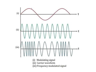
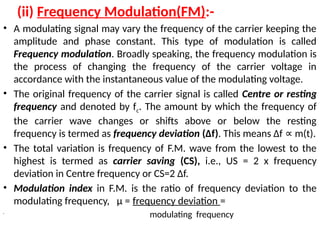
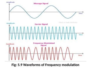
(ii) Frequency Modulation(FM):-
•A modulating signal may vary the frequency of the carrier keeping the
amplitude and phase constant. This type of modulation is called
Frequency modulation. Broadly speaking, the frequency modulation is
the process of changing the frequency of the carrier voltage in
accordance with the instantaneous value of the modulating voltage.
• The original frequency of the carrier signal is called Centre or resting
frequency and denoted by fc. The amount by which the frequency of
the carrier wave changes or shifts above or below the resting
frequency is termed as frequency deviation (Δf). This means Δf m(t).
∝
• The total variation is frequency of F.M. wave from the lowest to the
highest is termed as carrier saving (CS), i.e., US = 2 x frequency
deviation in Centre frequency or CS=2 Δf.
• Modulation index in F.M. is the ratio of frequency deviation to the
modulating frequency, µ = frequency deviation =
•
modulating frequency
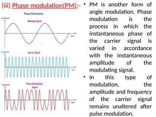
(iii) Phase modulation(PM):-• PM is another form of
angle modulation. Phase
modulation is the
process in which the
instantaneous phase of
the carrier signal is
varied in accordance
with the instantaneous
amplitude of the
modulating signal.
• In this type of
modulation, the
amplitude and frequency
of the carrier signal
remains unaltered after
pulse modulation.
40.
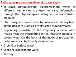
Radio wave propagation(Ground, space, sky):-
• In space communication electromagnetic waves of
different frequencies are used to carry information
through the physical space acting as the transmission
medium.
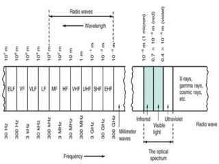
• Electromagnetic waves with frequencies extending from
about 10 kHz to 300 GHz are classified as radio waves.
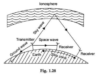
• Depending primarily on the frequency a radio wave
travels from the transmitting to the receiving antenna in
several ways. On the basis of the mode of propagation,
radio waves can be broadly classified as:
• Ground or Surface wave.
• Space or Tropospheric wave.
• Sky way.
43.
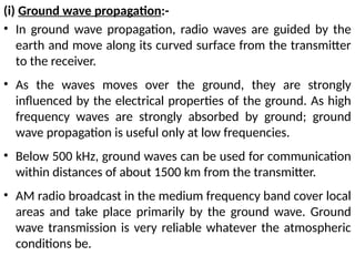
(i) Ground wavepropagation:-
• In ground wave propagation, radio waves are guided by the
earth and move along its curved surface from the transmitter
to the receiver.
• As the waves moves over the ground, they are strongly
influenced by the electrical properties of the ground. As high
frequency waves are strongly absorbed by ground; ground
wave propagation is useful only at low frequencies.
• Below 500 kHz, ground waves can be used for communication
within distances of about 1500 km from the transmitter.
• AM radio broadcast in the medium frequency band cover local
areas and take place primarily by the ground wave. Ground
wave transmission is very reliable whatever the atmospheric
conditions be.
44.
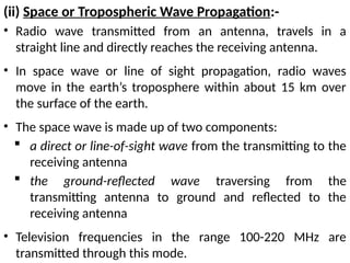
(ii) Space orTropospheric Wave Propagation:-
• Radio wave transmitted from an antenna, travels in a
straight line and directly reaches the receiving antenna.
• In space wave or line of sight propagation, radio waves
move in the earth’s troposphere within about 15 km over
the surface of the earth.
• The space wave is made up of two components:
a direct or line-of-sight wave from the transmitting to the
receiving antenna
the ground-reflected wave traversing from the
transmitting antenna to ground and reflected to the
receiving antenna
• Television frequencies in the range 100-220 MHz are
transmitted through this mode.
45.
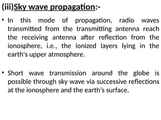
(iii)Sky wave propagation:-
•In this mode of propagation, radio waves
transmitted from the transmitting antenna reach
the receiving antenna after reflection from the
ionosphere, i.e., the ionized layers lying in the
earth's upper atmosphere.
• Short wave transmission around the globe is
possible through sky wave via successive reflections
at the ionosphere and the earth's surface.
46.
Digital Modulation Schemes:-
Advantagesof digital communication over analog
communication:-
• Immunity to Noise (possibility of regenerating the original
digital signal if signal power to noise power ratio (SNR) is
relatively high by using of devices called repeaters along the
path of transmission).
• Efficient use of communication bandwidth (through use of
techniques like compression).
• Digital communication provides higher security (data
encryption)
• The ability to detect errors and correct them if necessary.
• Design and manufacturing of electronics for digital
communication systems is much easier and much cheaper than
the design and manufacturing of electronics for analog
47.
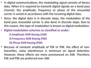
• In digitalcommunications, the modulating signal consists of binary
data. When it is required to transmit digital signals on a band pass
channel, the amplitude, frequency or phase of the sinusoidal
carrier is varied in accordance with the incoming digital data.
• Since, the digital data is in discrete steps, the modulation of the
band pass sinusoidal carrier is also done in discrete steps. Due to
this reason, this type of modulation is known as digital modulation.
• Digital modulation schemes as classified as under:
i) Amplitude Shift Keying (ASK)
ii) Frequency Shift Keying (FSK)
iii) Phase Shift Keying (PSK)
• Because of constant amplitude of FSK or PSK, the effect of non-
linearities, noise interference is minimum on signal detection.
However, these effects are more pronounced on ASK. Therefore,
FSK and PSK are preferred over ASK.
48.
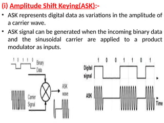
(i) Amplitude ShiftKeying(ASK):-
• ASK represents digital data as variations in the amplitude of
a carrier wave.
• ASK signal can be generated when the incoming binary data
and the sinusoidal carrier are applied to a product
modulator as inputs.
49.
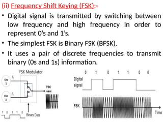
(ii) Frequency ShiftKeying (FSK):-
• Digital signal is transmitted by switching between
low frequency and high frequency in order to
represent 0’s and 1’s.
• The simplest FSK is Binary FSK (BFSK).
• It uses a pair of discrete frequencies to transmit
binary (0s and 1s) information.
50.
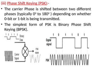
(iii) Phase ShiftKeying (PSK):-
• The carrier Phase is shifted between two different
phases (typically 00
to 1800
) depending on whether
0-bit or 1-bit is being transmitted.
• The simplest form of PSK is Binary Phase Shift
Keying (BPSK).
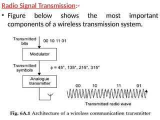
• The transmitteraccepts a stream of bits from the
application software.
• It then encodes these bits onto a radio wave, known
as a carrier, by adjusting parameters of the wave
such as its amplitude or phase.
• The transmitter usually processes the information in
two stages:
Modulator –accepts the incoming bits, and computes
symbols that represent the amplitude and phase of the
outgoing wave.
Analogue transmitter –generates the radio wave
53.
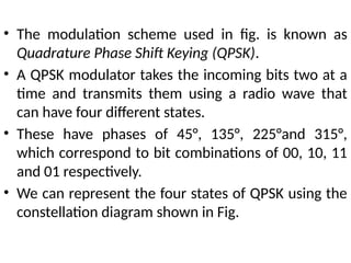
• The modulationscheme used in fig. is known as
Quadrature Phase Shift Keying (QPSK).
• A QPSK modulator takes the incoming bits two at a
time and transmits them using a radio wave that
can have four different states.
• These have phases of 45°, 135°, 225°and 315°,
which correspond to bit combinations of 00, 10, 11
and 01 respectively.
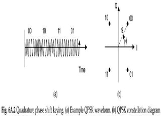
• We can represent the four states of QPSK using the
constellation diagram shown in Fig.
55.
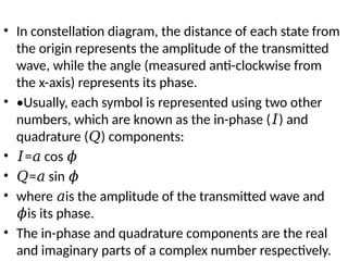
• In constellationdiagram, the distance of each state from
the origin represents the amplitude of the transmitted
wave, while the angle (measured anti-clockwise from
the x-axis) represents its phase.
• •Usually, each symbol is represented using two other
numbers, which are known as the in-phase ( ) and
𝐼
quadrature ( ) components:
𝑄
• 𝐼= cos
𝑎 𝜙
• 𝑄= sin
𝑎 𝜙
• where is the amplitude of the transmitted wave and
𝑎
is its phase.
𝜙
• The in-phase and quadrature components are the real
and imaginary parts of a complex number respectively.
56.
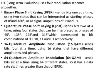
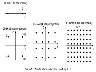
LTE (Long TermEvolution) uses four modulation schemes
altogether.
• Binary Phase Shift Keying (BPSK) –sends bits one at a time,
using two states that can be interpreted as starting phases
of 0°and 180°, or as signal amplitudes of +1and −1.
• Quadrature Phase Shift Keying (QPSK)–sends bits two at a
time, using four states that can be interpreted as phases of
45°, 135°, 225°and 315°which correspond to bit
combinations of 00, 10, 11 and 01 respectively.
• 16-Quadrature Amplitude Modulation (16-QAM)–sends
bits four at a time, using 16 states that have different
amplitudes and phases.
• 64-Quadrature Amplitude Modulation (64-QAM) –sends
bits six at a time using 64 different states, so it has a data
rate six times greater than that of BPSK.
58.
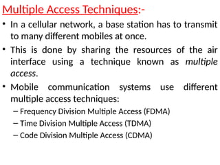
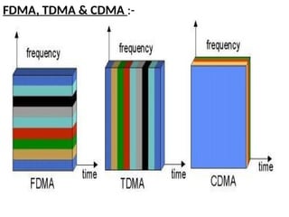
Multiple Access Techniques:-
•In a cellular network, a base station has to transmit
to many different mobiles at once.
• This is done by sharing the resources of the air
interface using a technique known as multiple
access.
• Mobile communication systems use different
multiple access techniques:
– Frequency Division Multiple Access (FDMA)
– Time Division Multiple Access (TDMA)
– Code Division Multiple Access (CDMA)
59.
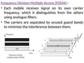
Frequency Division MultipleAccess (FDMA):-
• Each mobile receives signal on its own carrier
frequency, which it distinguishes from the others
using analogue filters.
• The carriers are separated by unused guard bands
to minimize the interference between them.
60.
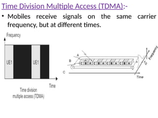
Time Division MultipleAccess (TDMA):-
• Mobiles receive signals on the same carrier
frequency, but at different times.
61.
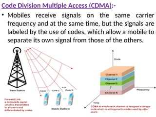
Code Division MultipleAccess (CDMA):-
• Mobiles receive signals on the same carrier
frequency and at the same time, but the signals are
labeled by the use of codes, which allow a mobile to
separate its own signal from those of the others.
• FDMA wasused by the first generation analogue
systems.
• GSM uses a mix of FDMA and TDMA, in which every cell
has several carrier frequencies that are each shared
amongst eight different mobiles.
• LTE uses another mixed technique known as Orthogonal
Frequency Division Multiple Access (OFDMA).
• CDMA is used by the third generation communication
systems.
• LTE uses a few of the concepts from CDMA for some of
its control signals, but does not implement the
technique otherwise.
64.
Multiplexing vs. MultipleAccess:-
• Multiple access is actually a generalization of a
simpler technique known as multiplexing.
• A multiple access system can dynamically change
the allocation of resources to different mobiles,
whereas in a multiplexing system the resource
allocation is fixed.
65.
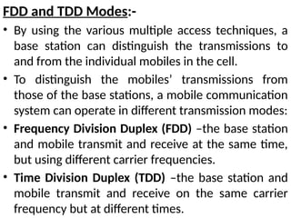
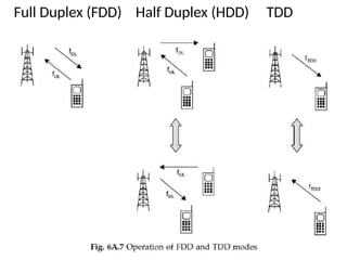
FDD and TDDModes:-
• By using the various multiple access techniques, a
base station can distinguish the transmissions to
and from the individual mobiles in the cell.
• To distinguish the mobiles’ transmissions from
those of the base stations, a mobile communication
system can operate in different transmission modes:
• Frequency Division Duplex (FDD) –the base station
and mobile transmit and receive at the same time,
but using different carrier frequencies.
• Time Division Duplex (TDD) –the base station and
mobile transmit and receive on the same carrier
frequency but at different times.
In FDD mode,
the bandwidths of the uplink and downlink are
fixed and are usually the same.
suitable for voice communications, in which the
uplink and downlink data rates are very similar.
In TDD mode,
the system can adjust how much time is allocated
to the uplink and downlink.
suitable for applications such as web browsing, in
which the downlink data rate can be much
greater than the rate on the uplink.
68.
QUESTION BANK
1. Drawthe block diagram of basic Communication System and briefly explain
each and every block.
2. Discuss the types of Communication Systems.
3. What is Modulation? Discuss the need for Modulation. Explain AM, FM & PM
with neat waveforms.
4. Explain with a neat diagram the concept of Radio Wave Propagation and its
different types.
5. List out the advantages of Digital Communication over Analog
Communications.
6. What is Digital Modulation? Explain the three types of digital modulation
schemes with neat circuit diagrams and waveforms.
7. Consider the following binary data and sketch the ASK, FSK & PSK modulated
waves:
Binary 1 0 0 1 1 0 1
Data