
More Related Content
Similar to Lec41
Recently uploaded
Recently uploaded (20)
Lec41
- 1. Control Systems Prof. C. S. Shankar Ram Department of Engineering Design Indian Institute of Technology, Madras Lecture - 41 Case Study-Modelling Part-1 Good morning. Let us get started today’s class. So, today what we will do is, consider a case study, not like we will start from deriving the equation of motion, deriving the transfer function and then like using that to design controllers to satisfy performance and stability, and then we also look at how to construct the root locus and use the root locus for designing the controller right. So, ultimately we go through the entire control design process for an example system right. So, that is something which we will start off today. (Refer Slide Time: 00:52) So, the system that you know like we are going to consider is a gear transmission, you know like which is a pretty common in many, what you say as practical systems today right. So, let us say you know I, we have an input gear that has N 1 teeth on it right and that is meshed with an output gear which has a 2 teeth on it right. So, we have the input shaft you know to which an input torque of T m is given to it you know like for example, this input torque could come from a motor right which is driving the input shaft right.
- 2. So and that input torque is going to drive the entire shaft and gear assembly; let us say that the moment of inertia of the entire input shaft and input gear assembly put together is some J 1 right. And the input shaft is supported on a bearing with a friction coefficient of f 1. So, the viscous friction coefficient is f 1; that means, that the frictional torque which is dissipated is essentially f 1 times omega 1 right, so that is the implication of that coefficient f 1 right. So and similarly the; of course, the angular displacement of the input shaft is let us say theta 1 t right, the angular displacement of the output shaft is going to be theta 2 and J 2 is the moment of inertia of the output shaft assembly along with the output gear right, f 2 is the corresponding friction coefficient right for the output gear. So, consequently the torque which is so essentially used up in over-coming friction of the output shaft is going to be f 2 times omega 2 right; so, that is the viscous friction coefficient. And.let us say you know like we have a load torque t l right; obviously, you know like the output is going to drive some load ok. See for example, you know like one could essentially use this arrangement to, let us say dry the wheel of a vehicle right. So, let us say you know you have a wheel of a car, you know which is loaded. So, it will basically provide some resistance right that is a load torque ok. So, we finally need to overcome the load torque and operate the output shaft at the desired state right. So, the first step you know like, is for us to essentially derive the governing equation of motion ok. So, we are going to essentially consider the, this entire entity as a system to which we can, we provide the torque T m t as the input and the angular displacement of the output shaft theta 2 t is the output ok, so that is the visualization. Of course this because you know like ultimately we are going to look at position control right. So, that is the objective that we are going to look at here, right. Let us say you know like I want to control the angular displacement of the output shaft you know like how do I do that ok. Of course, we alternatively we can also do consider the output to be omega 2 t ok, where in I want to do speed control or the output shaft right. I would do position control, I would leave speed control to you as a homework right so, but that is going to be pretty straightforward, at least the derivation of the transfer function is going to be pretty straightforward right, once we do this derivation
- 3. right, the controller part needs to be redone. So, let us first derive the governing equations of motion that is the first task that we are going to do. So, let us get started with that ok. To do that let us draw the free body diagram of the input shaft right. So, let us first draw the free body diagram of the input shaft, then let us write down the corresponding equation of motion. So, let us say I draw the input shaft ok; so, what are all the torques that are going to act on this input shaft? So, essentially we have the input torque T m t is acting. So, are there some resisting torques? Yes there are right. So, we have one due to friction, which is f 1 times theta 1 dot t and would there be any other torque which would be essentially in a sense resisting the motion of the input; torque input shaft? Please note that the input shaft is driving the output shaft right. So; obviously, the output shaft is going to exert a reaction right, for the action that input shaft takes on, does on the output shaft right. Lets say we call this is reaction torque as some T 1 t ok. So, T 1 t is essentially the reaction torque from the output shaft to the input shaft due to the fact that the input shaft is driving the output shaft right. So, these are the torques that are acting on the input shaft right. So, if we write down the equation of motion, so what is going to happen. So, J 1 times theta 1 double dot t; that is going to be equal to the net torque which is acting on this body right, that is going to be the more input torque T m t minus f 1 theta 1 dot t and then minus T 1 t ok. So, that is what we are going to write. So, just rearranging these terms you know we will get the equation as J 1 times theta 1 double dot t plus f 1 theta 1 dot t is equal to T m t minus T 1 t ok. So, that is let us call this is equation number 1 right. So, that is a governing equation for the a input shaft. So, similarly let us draw the free body diagram for the output shaft and see what happens right. So, if I draw the free body diagram for the output shaft, what is going to happen? I am going to get this right. So, as far as the output shaft is concerned, you know like I need some torque to dry the output shaft right. So, let us say we call that driving torque as T 2 t alright that is what comes from the input shaft right.
- 4. So, essentially that is the driving torque right, so as far as the output shaft is concerned. and what are the resisting torques, you know like we are going to have a friction torque f 2 times theta 2 dot t and of course, the load torque is in, torque which is going to essentially resist the motion of the output shaft right. So, that is going to be another thing right. So, what we are going to have essentially is, J 2 dot theta 2, J 2 times theta 2 double dot that is going to be equal to T 2 t minus f 2 theta 2 dot t minus T L t right, that is going to be a the governing equation. So, just rearranging the terms, you know like we get the equation as J 2 times theta 2 double dot plus f 2 times theta 2 dot that is going to be equal to T 2 t minus T L t ok. So, let us call this is equation number 2 ok. So, those are the 2 equations right. Now of course, you know like we need to eliminate T 1 T 2 and theta 1 right, because ultimately we want one consolidated equation relating the output to the input right. So, if you recall that is what we are aiming for right. So, as far as our framework is concerned, ultimately if we identify a system with an input and an output, we want a governing linear o d that relates the input to the output right. So, our input is T m output is theta 2. So, we should have an o d only relating those two variables right, T L, T 1 can model it as a disturbance ok. So, we will come to that later so, but then like, let us try to see how we can eliminate it. Now you know please note that N 1 and N 2 are system parameters right. So, the input gear as N 1 teeth and the output gear as N 2 teeth right. Can we use this information to relate theta 1 and theta 2? Assuming that there is no slip at the gear interface, you know like what is, how are theta 1 theta 2 N 1 N 2 related?
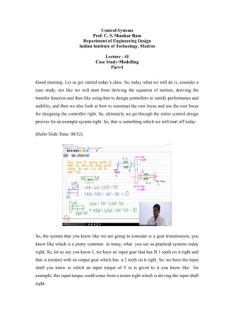
- 5. (Refer Slide Time: 10:41) What will be the relationship between the variables theta 1 theta 2 and N 1 and N 2? see of course, there are various ways to look at it, you know like see if two gears are in meshing, are in mesh with each other you know like essentially that pitch should be the same right. Then only they will mesh with each other right using those ideas you know one can easily get an relationship. I will write down the relationship you think about it as homework ok. So, you figure it out as to how we can get it ok. So, immediately one can know that a, essentially theta 2 t divided by theta 1 t that is going to be equal to N 1 by N 2 ok, so that is what we are going to have ok. So, there is going to be a relationship between the angular displacements and the number of teeth in the two gears in this manner ok. So, that is what we are going to get as far as this gear is concerned. and of course, if once we have this, you know like we want to essentially eliminate theta 1, so what you can really see that, is the following; theta 1 is going to be equal to N 2 by N 1 theta 2 t right, correct from this equation. So, this implies that I can write theta 1 dot as N 2 by N 1 theta 2 dot right. Similarly I can write theta 1 double dot is going to be equal to N 2 by N 1, theta 2 double dot right. You can write all these equations right, so once we figure this one correct ok. So, that that takes care of theta 1 right, so I can eliminate theta 1 from theta 1 double dot and theta 1 dot from equation 1, but now I need to figure out what to do with T 1 and T 2
- 6. is there a a relationship between T 1 and T 2? Yes that is right, because the energy should be conserved all right when when essentially the system is all operation right. So, if you consider the interface, you know like. So, of course, we make an assumption that we neglect energy losses ok, of course, a if you do not neglect energy losses, you know typically we need to put an efficiency term ok like. So, neglecting energy losses, we can immediately see that T 1 T 1 t theta 1 t that is a work done by the input shaft right; that is going to be equal to T 2 t times theta 2 t right; that is going to be the what to say energy balance or the gear interface right, the gear mesh ok. Of course, a if we want to take into account our energy loss what what we can do is a. Here I can multiply by a efficiency term, a transmission efficiency ok. so; that means, that because the output, there is going to be some energy dissipation at the what to say gear interface due to friction and so on right, so what to say, it is not perfect right. So, whats what we will have is that like we may have some frictional losses, but for the time being we will neglect them alright. So, essentially what if someone wants to incorporate it you multiply the factor theta, sorry the term T T 1 t theta 1 t with an efficiency eta t, and that is going to be equal to the energy term T 2 t times theta 2 t alright. so, but for the time being we will consider eta t to be hundred percent ok just for a simplicity ok, but if someone gives us this parameter we can we can of course, incorporate it ok; that is what I just wanted to convey through you right. So, this one, this is T 1 t times theta 1 t ok. So, this immediately tells us, what does this tell us? This immediately gives us that T 1 t theta 1 t divided by theta 2 t is equal to T 2 t ok. this similarly gives us the T 2 t is going to be equal to T 1 t ok N 2 by N 1 right, why because the theta 1 by theta 2 is N 2 by N 1 ok, so thats how we get this relationship ok now we are all set ok. So, now let us go back to equation number 1 ok. And let us say we take equation number 1 and multiply both sides by N 2 by N 1 ok. Let us take it equation number 1 let us multiply both sides by N 2 by N 1, I can do that right. So, then what will I get? I will get J times sorry J 1 times N 2 by N 1 theta 1 double dot t plus f 1 theta 1 dot t; that is going to be equal to T m t minus T 1 t N 2 by N 1 ok. That is what I will get right, after once I
- 7. want to try by N 2 by N 1 on both sides right. So, now, I plug in for substitute for theta 1 double dot and theta 1 dot right. So, if I substitute for theta 1 double dot, theta 1 double dot is going to be a N 2 by N 1, theta 2 double dot right. So, let us substitute that. (Refer Slide Time: 17:18) So, what will happen this will become N 2 by N 1 whole square theta 2 double dot right, so that is what is going to happen here ok. Of course, I think I missed an N 2 by N 1 here right, because obviously, you know like I am multiplying both sides by N 2 by N 1 right, even f 1 should be multiplied by N 2 by N 1 right. Sorry about that even T m t right, so ok sorry about that right. So, of course, equation 1 I am multiplying both sides by N 2 by N 1. I think I missed those two terms sorry. So, consequently if I substitute for theta 1 dot, this is going to be f 1 times N 2 by N 1 whole square theta 2 dot ok, and that is going to be N 2 by N 1 or T m t minus T 2 t. do you agree? Why did I get T 2 t, because T 2 t is T 1 t times N 2 by N 1 right, so that is why we have this right. Now, we are almost through ok. So, what do we do? We just add 2 and 3 ok. So, let us say you know like, let us do 2 plus 3. So, what will 2 plus 3 give me, it will give me J 1 N 2 by N 1 whole square plus J 2 theta 2 double dot t plus f 1 N 2 by N 1 whole square plus f 2 theta 2 dot t; that is going to be equal to N by N 1 T m t minus T L t ok. So, this is the governing equation for this gear transmission system right.
- 8. So, you see that, you know we have in the form that we want right. So, that is we want on the left hand side the output and the derivatives, right hand side we want the input and the derivatives right, but if you look at the right hand side, we have the input T m t and T L t, you know like as I told you T L t is an input which comes into the system, but we can treat it as a disturbance right. So, because we need to overcome it right, is it not correct, so we give a load torque, essentially I need to overcome that load torque right. I need to apply an input which will overcome that ok. So, that is something which we need to account for ok. So, I hope this is clear, right until this point.