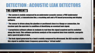
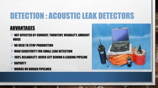
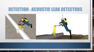
The document discusses flanges, valves, causes of flange and valve leakage, detection of leaks using acoustic leak detectors, and prevention of leaks through flangebelts and automatic water shutoff valves. Flanges are rims or ridges used to join pipes and withstand pressure. Valves regulate fluid flow by opening, closing, or partially blocking passages. Common causes of leakage are improper bolt tightening, misalignment, thermal effects, and dirty or damaged surfaces. Acoustic leak detectors use underwater sensors to detect leak sounds. Flangebelts and automatic shutoff valves can help prevent leaks by sealing flanges and stopping water flow if a leak is detected.
Any type of pipeline pigging requires extensive planning, and professional assistance for either the pig manufacturers or a qualified pipeline cleaning service company
The pressure test is a key event in the installation of all Fusible PVC® products, including Fusible C-900®, Fusible C-905®, and FPVC®. There are, in a lot of installations, more events beyond the pressure test that define completion of the project. For pipe supply and fusion services however, the pressure test can define completion of services in the manner expected
1. Purpose of Hydro test.
2. Types of Pressure Test.
3. Procedure of Hydro test.
4. Limitations of Pneumatic Test.
5. Hydro testing test Pressure.
6. Test pressure subjected to external pressure.
7. Hydro test Pressure according to different process.
8. Volume required for the Hydro testing.
9. Pipeline De watering, Cleaning & Drying.
Presentation on O & M of gates by Shri N Kannaiah Naydu,during
One Day Seminar on Safety Inspection and O & M of gates for dams, canals etc
conducted by Gujarat State Center of The Institution of Engineers (India) at Ahmedabad on July 3, 2015.
Video can be seen on facebook as well as Youtube page of IEIGSC.
Quality aspects in Cross Country Pipeline constructionSuresh Zanwar
Quality aspects in Cross Country Pipeline construction
Alignment of Pipeline & precautions
Soil erosion in hilly areas & precaution in ROU grading
How pipelines get laid at lower cover & precautions in trenching
Where line pipe string is important and control needed
How to control failure of welding joints
What affects in field coating joint
Pipeline lowering & stress on pipeline – Best laid Pipeline experience
How backfilling makes difference in Pipeline corrosion
How pipeline get exposed on river banks & precaution in river crossing
Safety aspects in Pipeline construction
Why casing & carrier pipe gets shorted
How to make river bank protection
Where cathodic protection fails
Steam traps are the hardest working components in the steam system. Maintenance or replacement of steam traps must be as quick and efficient as possible to avoid unnecessary disruption to related processes.
Traditional steam trapping assemblies often require the plant to be shut down for traps to be maintained or replaced taking significant time and reducing production output.
The PC3000 and PC4000 incorporate isolation valves, strainer, two-bolt steam trap connection and blowdown valves, all in a single unit for quick and easy installation and operation.
A process flow diagram (PFD) is a diagram commonly used in chemical and process engineering to indicate the general flow of plant processes and equipment.
Controlling Cavitation in Industrial Control ValvesCTi Controltech
Cavitation, in process control valves, refers to the formation of vapor spaces or bubbles within the valve cavity resulting from a rapid drop in pressure as liquid passes through the valve. When the bubbles transit to an area of higher pressure, the higher pressure causes the bubbles to implode, producing shockwaves which propagate through the liquid. These shockwaves can cause metal fatigue and excessive wear on the internals of the valve. The collapsing bubbles also make a discernible sound with accompanying vibration.
Flowserve provides an introduction to cavitation with velocity profile, pressure profile, effects of cavitation, flashing, sound, and other aspects covered. The theory behind controlling cavitation and various methods employed in the company's valve products is also included.
Cavitation Reduction in Industrial Process Control ValvesCTi Controltech
In many control valves, the pressure at the vena contracta
will drop below the vapor pressure of the liquid. When
this occurs, small bubbles of gas will form as the liquid
vaporizes. As the pressure then rises above the vapor
pressure again, these small bubbles collapse or implode
as the vapor turns back into liquid. The damage is inflicted
as the bubbles implode. The implosion of the vapor
bubbles is very energetic and forms jets of fluid which can
tear small pits into the metal. This is called cavitation.
Cavitation damage destroys both piping and control
valves, often resulting in catastrophic failure. It causes
valves to leak by eroding seat surfaces. It can drill holes
through pressure vessel walls. Even low levels of cavitation
will cause cumulative damage, steadily eroding parts
until the part is either repaired, or it fails.
This Slideshare explains valve cavitation and provides solutions to minimize or eliminate its effects.
Cavitation is a phenomenon that can occur in a liquid process whenever there is a drop in pressure. Cavitation should be avoided, since it produces destructive forces in the liquid that damage valves, pumps, and other equipment.
A Control Valve is the most commonly used
final control element used to regulate fluid flow in
a process. In a process, normally it is the only
controllable element residing in the loop.
Ø This is a device used to modulate flow of
process fluid in pipe lines by creating a variable
area in the flow path.
Ø The flow path is varied with respect to the
control signal received from the controller
towards the required flow modulation.
Detailed description of the background for developing Smart Water Valve, as well as details on the types of water leak problems that can be solved. Also, details on the unique patented technology and how it works
Unit 8 - Information and Communication Technology (Paper I).pdfThiyagu K
This slides describes the basic concepts of ICT, basics of Email, Emerging Technology and Digital Initiatives in Education. This presentations aligns with the UGC Paper I syllabus.
How to Make a Field invisible in Odoo 17Celine George
It is possible to hide or invisible some fields in odoo. Commonly using “invisible” attribute in the field definition to invisible the fields. This slide will show how to make a field invisible in odoo 17.
Acetabularia Information For Class 9 .docxvaibhavrinwa19
Acetabularia acetabulum is a single-celled green alga that in its vegetative state is morphologically differentiated into a basal rhizoid and an axially elongated stalk, which bears whorls of branching hairs. The single diploid nucleus resides in the rhizoid.
Francesca Gottschalk - How can education support child empowerment.pptxEduSkills OECD
Francesca Gottschalk from the OECD’s Centre for Educational Research and Innovation presents at the Ask an Expert Webinar: How can education support child empowerment?
Read| The latest issue of The Challenger is here! We are thrilled to announce that our school paper has qualified for the NATIONAL SCHOOLS PRESS CONFERENCE (NSPC) 2024. Thank you for your unwavering support and trust. Dive into the stories that made us stand out!
2024.06.01 Introducing a competency framework for languag learning materials ...Sandy Millin
http://sandymillin.wordpress.com/iateflwebinar2024
Published classroom materials form the basis of syllabuses, drive teacher professional development, and have a potentially huge influence on learners, teachers and education systems. All teachers also create their own materials, whether a few sentences on a blackboard, a highly-structured fully-realised online course, or anything in between. Despite this, the knowledge and skills needed to create effective language learning materials are rarely part of teacher training, and are mostly learnt by trial and error.
Knowledge and skills frameworks, generally called competency frameworks, for ELT teachers, trainers and managers have existed for a few years now. However, until I created one for my MA dissertation, there wasn’t one drawing together what we need to know and do to be able to effectively produce language learning materials.
This webinar will introduce you to my framework, highlighting the key competencies I identified from my research. It will also show how anybody involved in language teaching (any language, not just English!), teacher training, managing schools or developing language learning materials can benefit from using the framework.
A Strategic Approach: GenAI in EducationPeter Windle
Artificial Intelligence (AI) technologies such as Generative AI, Image Generators and Large Language Models have had a dramatic impact on teaching, learning and assessment over the past 18 months. The most immediate threat AI posed was to Academic Integrity with Higher Education Institutes (HEIs) focusing their efforts on combating the use of GenAI in assessment. Guidelines were developed for staff and students, policies put in place too. Innovative educators have forged paths in the use of Generative AI for teaching, learning and assessments leading to pockets of transformation springing up across HEIs, often with little or no top-down guidance, support or direction.
This Gasta posits a strategic approach to integrating AI into HEIs to prepare staff, students and the curriculum for an evolving world and workplace. We will highlight the advantages of working with these technologies beyond the realm of teaching, learning and assessment by considering prompt engineering skills, industry impact, curriculum changes, and the need for staff upskilling. In contrast, not engaging strategically with Generative AI poses risks, including falling behind peers, missed opportunities and failing to ensure our graduates remain employable. The rapid evolution of AI technologies necessitates a proactive and strategic approach if we are to remain relevant.
Biological screening of herbal drugs: Introduction and Need for
Phyto-Pharmacological Screening, New Strategies for evaluating
Natural Products, In vitro evaluation techniques for Antioxidants, Antimicrobial and Anticancer drugs. In vivo evaluation techniques
for Anti-inflammatory, Antiulcer, Anticancer, Wound healing, Antidiabetic, Hepatoprotective, Cardio protective, Diuretics and
Antifertility, Toxicity studies as per OECD guidelines
2. FLANGE
A flange is an external or internal ridge, or rim (lip), for
strength, or for attachment to another object, as the flange
on the end of a pipe .
pipes with flanges can be assembled and disassembled
easily. Some type of materials use to manufacture flanges
are cast iron, carbon steel, 12mo-steel, al steel .
A flange can also be a plate or ring to form a rim at the end
of a pipe when fastened to the pipe.
3. VALVE
A valve is a device that regulates, directs or controls the flow of
a fluid (gases, liquids, fluidized solids, or slurries) by opening,
closing, or partially obstructing various passageways.
In an open valve, fluid flows in a direction from higher pressure
to lower pressure.
The simplest, and very ancient, valve is simply a freely hinged
flap which drops to obstruct fluid (gas or liquid) flow in one
direction, but is pushed open by flow in the opposite direction.
This is called a check valve, as it prevents or "checks" the flow
in one direction.
Valves are also used in the military & transport sectors.
4. CAUSES : FLANGE LEAKAGE
UNEVEN BOLT STRESS
An incorrect tightening/assembly procedure or
difficult access to fasteners can leave some bolts
loose while others are over tightened and can crush
the gasket.
This can cause in-service leaks, especially in high
temperature services when the heavily loaded bolts
relax.
5. CAUSES: FLANGE LEAKAGES
IMPROPER FLANGE ALIGNMENT
Flange face parallelism causes uneven gasket
compression, local crushing, and can cause
subsequent leakage.
Improper flange centerline alignment can also
cause uneven gasket compression and flange
leaks.
6. CAUSES: FLANGE LEAKAGES
THERMAL SHOCK
Rapid temperature fluctuations can cause flanges to deform temporarily.
This is typically a greater potential problem in high temperature
applications.
Temperature variations cannot always be avoided.
Thermal gradients across the flange and cause leakage.
7. CAUSES: FLANGE LEAKAGES
DIRTY OR DAMAGED FLANGE FACES
Dirt, scale, scratches, protrusions, weld
spatter on gasket seating surfaces, and warped
seating surfaces provide leakage paths or can
cause uneven gasket compression that can
result in flange leakage.
8. CAUSES: VALVE LEAKAGES
OFTEN LARGE DIAMETER BLOCK VALVES ARE STORED ON A DUSTY CONSTRUCTION
SITE WITH NO END COVERS OR ALTERNATIVE PROTECTION FROM AIRBORNE
CONTAMINANTS.
VALVE IS NOT FULLY CLOSED
THE VALVE SEALS ARE DAMAGED
SHELL'S SECOND OIL LEAK IN NORTH SEA PIPELINE CAUSED BY RELIEF VALVE
9. DETECTION : ACOUSTIC LEAK DETECTORS
( SUBSEA LEAK DETECTION TECHNIQUE )
WORKING PRINCIPLE
A pipeline leakage consists in the transition of a fluid from the inside pressure
to the lower external pressure.
This creates an acoustic signal due to the turbulence and to the sudden
expansion of the fluid mass.
ALD is capable to acquire and process the acoustic data in order to extract this
leakage signal from the ambient noise
10. DETECTION : ACOUSTIC LEAK DETECTORS
THE EQUIPMENT'S
The system is mainly composed by an underwater acoustic sensor, a POD (underwater
electronic unit), a transmission line, a receiving unit and a PC based processing and display
software.
The sensor is driven along the pipeline or positioned close to a flange or connection, the
receiver puts the operator in condition of identifying an eventual leak signal.
A proprietary software allows to evaluate in real time the signal acquired and its evolution
along the track. This software performs analysis of the acquired data from statistic, energetic
and a spectral point of view.
The leak signal generated by a leak is mainly composed by ultrasound, the ALD receiver shifts
this signal to audible lower frequency generating a “virtual audio” .
11. DETECTION : ACOUSTIC LEAK DETECTORS
ADVANTAGES
NOT AFFECTED BY CURRENT, TURBITIDY, VISIBILITY, AMBIENT
NOISE
NO NEED TO STOP PRODUCTION
HIGH SENSITIVITY FOR SMALL LEAK DETECTION
100% RELIABILITY: NEVER LEFT BEHIND A LEAKING PIPELINE
RAPIDITY
WORKS ON BURIED PIPELINES
12. DETECTION : ACOUSTIC LEAK DETECTORS
HOW TO DETECT THE LEAKS?
The diver handles the sensor and drives it around the flange to be inspected, data are sent by a
soft-cable to the surface receiver.
The ALD operator is in continuous communication with the diver and monitors the result of
data processing.
The sensor is neutral in water and very easy to handle, an underwater POD is fixed to the diver
safety bottle.
Very accurate inspections of flanges, valves, short pipeline segments.
• THE ALD TECHNOLOGY HAS BEEN MADE AVAILABLE IN A DIVERHAND HELD INSTRUMENT, WITHOUT ANY
NEED OF CONNECTIONS TO THE SURFACE THE DIVER OPERATES AUTONOMOUSLY.
14. PREVENTIONS: FLANGEBELT
SPECIFICATIONS
Manufactured in stainless steel (various grades).
The inner lining which can either be tight cells foam or teflon
offers a firm watertight seal
The flangebelt can be equipped with a small glass sampling bottle
as a sealed leak-detection device.
15. PREVENTIONS: FLANGEBELT
ADVANTAGES :
Slows down the formation of rust
No corrosion, as rust cannot develop on parts where the flange rests.
Can be used again and again after dismantling.
Long-life expectancy.
Leaks can be detected on isolated flanges
16. PREVENTIONS: FLANGEBELT
FITTING INSTRUCTIONS
Place the REMOVE FLANGEBELT around the flange.
Using a screwdriver on the fixation system, tighten the
remove flangebelt until perfectly tight.
Optional leak detection system available: small nozzle
and/or bottle
18. PREVENTION : AUTOMATIC WATER SHUTOFF VALVE
Automatic water shutoff valves use a water sensor that is placed on the floor to detect water
seapage or leakage.
This sensor is connected to to the water valve that controls the water fow.
If a leak is detected, the water valve turns off the water valve and stops the flow of water to the
appliance or device.
The signal is actually an electrical signal from the sensing pad to the control unit that activates
a magnetic shutoff valve.
19. PREVENTION : AUTOMATIC WATER SHUTOFF VALVE
INSTALLING AN AUTO SHUT OFF VALVE
First note the top and bottom of the shut off valve, the bottom has
screws and the top has in/out marks.
The red line exits from the last carbon block, enters the "in" on
the top of the valve, exits through the "out" on the top of the valve
and enters the ro membrane.
The blue line exits the ro membrane as filtered water, goes
through the bottom of the valve to the di resin or storage tank. The
"in" and "out" portions are interchangeable for the blue line