
Recommended
More Related Content
Viewers also liked
Viewers also liked (17)
Similar to Leading Naval Architectural Firm Leverages 3D to Solve Large Scale Problems
Similar to Leading Naval Architectural Firm Leverages 3D to Solve Large Scale Problems (20)
Recently uploaded
Recently uploaded (20)
Leading Naval Architectural Firm Leverages 3D to Solve Large Scale Problems
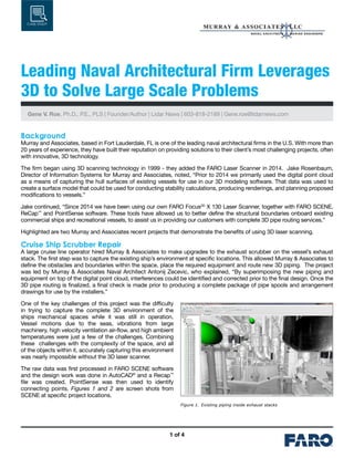
- 1. 1 of 4 CASE STUDY Leading Naval Architectural Firm Leverages 3D to Solve Large Scale Problems Gene V. Roe, Ph.D., P.E., PLS | Founder/Author | Lidar News | 603-818-2189 | Gene.roe@lidarnews.com Background Murray and Associates, based in Fort Lauderdale, FL is one of the leading naval architectural firms in the U.S. With more than 20 years of experience, they have built their reputation on providing solutions to their client’s most challenging projects, often with innovative, 3D technology. The firm began using 3D scanning technology in 1999 - they added the FARO Laser Scanner in 2014. Jake Rosenbaum, Director of Information Systems for Murray and Associates, noted, “Prior to 2014 we primarily used the digital point cloud as a means of capturing the hull surfaces of existing vessels for use in our 3D modeling software. That data was used to create a surface model that could be used for conducting stability calculations, producing renderings, and planning proposed modifications to vessels.” Jake continued, “Since 2014 we have been using our own FARO Focus3D X 130 Laser Scanner, together with FARO SCENE, ReCap™ and PointSense software. These tools have allowed us to better define the structural boundaries onboard existing commercial ships and recreational vessels, to assist us in providing our customers with complete 3D pipe routing services.” Highlighted are two Murray and Associates recent projects that demonstrate the benefits of using 3D laser scanning. Cruise Ship Scrubber Repair A large cruise line operator hired Murray & Associates to make upgrades to the exhaust scrubber on the vessel’s exhaust stack. The first step was to capture the existing ship’s environment at specific locations. This allowed Murray & Associates to define the obstacles and boundaries within the space, place the required equipment and route new 3D piping. The project was led by Murray & Associates Naval Architect Antonij Zecevic, who explained, “By superimposing the new piping and equipment on top of the digital point cloud, interferences could be identified and corrected prior to the final design. Once the 3D pipe routing is finalized, a final check is made prior to producing a complete package of pipe spools and arrangement drawings for use by the installers.” One of the key challenges of this project was the difficulty in trying to capture the complete 3D environment of the ships mechanical spaces while it was still in operation. Vessel motions due to the seas, vibrations from large machinery, high velocity ventilation air-flow, and high ambient temperatures were just a few of the challenges. Combining these challenges with the complexity of the space, and all of the objects within it, accurately capturing this environment was nearly impossible without the 3D laser scanner. The raw data was first processed in FARO SCENE software and the design work was done in AutoCAD® and a Recap™ file was created. PointSense was then used to identify connecting points. Figures 1 and 2 are screen shots from SCENE at specific project locations. Figure 1. Existing piping inside exhaust stacks
- 2. 2 of 4 Leading Naval Architectural Firm Leverages 3D to Solve Large Scale Problems The final deliverables for the scrubber project included a complete set of pipe spool and arrangement drawings. The physical pipe spools are then pre-fabricated and sent to the ship, where they are installed while the ship is in operation, so as to prevent any disruption of its schedule. From figures 3 and 4 it is clear to see the complexity of the vessel’s machinery spaces, and the numerous objects that are required to be accurately captured during the scanning process. Antonij noted, “Documenting all of this information without the 3D scanning technology is nearly impossible. Without 3D technology, the physical piping would likely have to be field routed, requiring more time and expense. A precise Bill of Material wouldn’t be possible, causing material waste, and potential interferences and issues may not be foreseen.” Below are a few samples of 3D pipes superimposed over the digital point cloud, pipe spools and pipe arrangement drawings, as well as 3D model – “as installed” comparisons. Figure 3. New piping and existing environment synergy Figure 4. Scrubbers process water equipment placed within existing pump room Figure 5. Process water equipment and piping modeled using ShipConstructor – Deck 01 Figure 6. Deck 01 process water equipment and piping installed Figure 2. Economizers steam manifold
- 3. 3 of 4 Container Ship Repair A container ship was involved in a collision with another large ship, resulting in significant damage to one side of the ship. Portions of the shell plating, framing, and ballast tanks were damaged and required repair. It was of utmost importance to complete these repairs as soon as possible, so that the ship could continue with its scheduled trade voyages. Knowing that the ships structure was symmetrical, they were able to scan both the damaged and undamaged sides of the vessel, both internally and externally. These scans were then mirrored atop of one another to determine the overall extent of the ship’s damage, and assist in developing a 3D structural model of all of the replacement steel components. Once the actual scans were registered and correctly aligned to the ship’s global coordinate system, a ReCap™ file was created. That ReCap file was then imported into AutoCAD® and the geometry was developed in 3D as an overlay on the digital point cloud using PointSense. The model was then compared to reference dimensions taken by traditional 2D measurements, as a final check. Jake Rosenbaum explained, “Using this model, structural components were then CNC cut and assembled off-site as a series of repair modules that were then fitted to the ship. This method resulted in a ‘glove like’ fit of the new steel sections. All of this work was done in a very short time frame, allowing the ship to return to service as quickly as possible.” Below are a few pictures showing the results that were accomplished by combining the FARO 3D scanning technology, and Murray & Associates’ engineering and industry know-how. Leading Naval Architectural Firm Leverages 3D to Solve Large Scale Problems Figure 7. Deck 02 process water and cooling water equipment and piping 3D model Figure 8. Deck02 process and cooling water equipment and piping installed Figure 9. Ship’s deck scan Figure 10. Ships hull scan
- 4. 4 of 4 Future Improvements Murray and Associates works in a highly demanding environment that presents a unique set of challenges that FARO is addressing with future product upgrades. When asked about areas where the technology could be improved, Jake saw the need for better target-based registering algorithms for easier, less time consuming registering of scans. He noted, “Since many of our scans are taken inside the vessel (enclosed steel box), only target-based registering is possible.” View more of FARO’s case studies at www.faro.com Leading Naval Architectural Firm Leverages 3D to Solve Large Scale Problems © 2016 FARO Technologies, Inc. All Rights Reserved. This case study is for informational purposes only. FARO makes no warranties–express or implied–in this case study. FARO, THE MEASURE OF SUCCESS and the FARO Logo are registered trademarks and trademarks of FARO Technologies, Inc. Figure 13. Units 1-4 and 6 fitted Figure 14. Ship is ready for service Figure 11. Vessels damaged structure Figure 12. Fitting of Unit 6