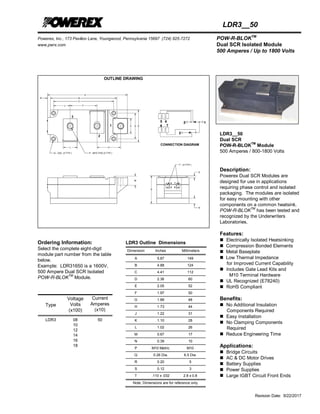
Powerex, Inc., 173 Pavilion Lane, Youngwood, Pennsylvania 15697 (724) 925-7272 POW-R-BLOKTM
www.pwrx.com Dual SCR Isolated Module
500 Amperes / Up to 1800 Volts
Revision Date: 9/22/2017
LDR3__50
OUTLINE DRAWING
Ordering Information:
Select the complete eight-digit
module part number from the table
below.
Example: LDR31650 is a 1600V,
500 Ampere Dual SCR Isolated
POW-R-BLOKTM
Module.
Type
Voltage
Volts
(x100)
Current
Amperes
(x10)
LDR3 08
10
12
14
16
18
50
LDR3 Outline Dimensions
Dimension Inches Millimeters
A 5.87 149
B 4.88 124
C 4.41 112
D 2.36 60
E 2.05 52
F 1.97 50
G 1.89 48
H 1.73 44
J 1.22 31
K 1.10 28
L 1.02 26
M 0.67 17
N 0.39 10
P M10 Metric M10
Q 0.26 Dia. 6.5 Dia.
R 0.20 5
S 0.12 3
T .110 x .032 2.8 x 0.8
Note: Dimensions are for reference only.
LDR3__50
Dual SCR
POW-R-BLOKTM
Module
500 Amperes / 800-1800 Volts
Description:
Powerex Dual SCR Modules are
designed for use in applications
requiring phase control and isolated
packaging. The modules are isolated
for easy mounting with other
components on a common heatsink.
POW-R-BLOK
TM
has been tested and
recognized by the Underwriters
Laboratories.
Features:
 Electrically Isolated Heatsinking
 Compression Bonded Elements
 Metal Baseplate
 Low Thermal Impedance
for Improved Current Capability
 Includes Gate Lead Kits and
M10 Terminal Hardware
 UL Recognized (E78240)
 RoHS Compliant
Benefits:
 No Additional Insulation
Components Required
 Easy Installation
 No Clamping Components
Required
 Reduce Engineering Time
Applications:
 Bridge Circuits
 AC & DC Motor Drives
 Battery Supplies
 Power Supplies
 Large IGBT Circuit Front Ends
Powerex, Inc., 173 Pavilion Lane, Youngwood, Pennsylvania 15697 (724) 925-7272 POW-R-BLOKTM
www.pwrx.com Dual SCR Isolated Module
500 Amperes / Up to 1800 Volts
Revision Date: 9/22/2017
LDR3__50
Absolute Maximum Ratings
Characteristics Conditions Symbol Units
Repetitive Peak Forward and Reverse Blocking
Voltage
VDRM & VRRM up to 1800 V
Non-Repetitive Peak Blocking Voltage
(t < 5 msec)
VRSM VRRM + 100 V
RMS Forward Current 180° Conduction, TC=85°C, 50 Hz IT(RMS) 785 A
Average Forward Current 180° Conduction, TC=85°C, 50 Hz IT(AV) 500 A
Peak One Cycle Surge Current, Non-Repetitive 60 Hz, 0V reapplied, Tj= Tj max ITSM 17,000 A
60 Hz, 0V reapplied, Tj= 25 °C ITSM 20,000 A
50 Hz, 0V reapplied Tj= Tj max ITSM 15,500 A
50 Hz, 0V reapplied, Tj= 25 °C ITSM 18,000 A
I
2
t for Fusing for One Cycle 60 Hz, 0V reapplied, Tj= Tj max I
2
t 1.19 x 10
6
A
2
sec
60 Hz, 0V reapplied, Tj= 25 °C I
2
t 1.66 x 10
6
A
2
sec
50 Hz, 0V reapplied Tj= Tj max I
2
t 1.20 x 10
6
A
2
sec
50 Hz, 0V reapplied, Tj= 25 °C I
2
t 1.62 x 10
6
A
2
sec
Average Forward Gate Power PG(AV) 4 W
Maximum Rate-of-Rise of On-State Current,
(Repetitive)
T= Tj max, VD= 0.67 VDRM,
ITM= 2 ITAV,
Gate Pulse: IG= 2 A, tGP= 50 µs,
diG/dt>= 1 A/µs
di/dt 400 A/µs
Operating Temperature TJ -40 to +130 °C
Storage Temperature Tstg -40 to +125 °C
Max. Mounting Torque, M6 Mounting Screw 55
6
in. – Lb.
Nm
Max. Mounting Torque, M10 Terminal Screw 110
12
in. – Lb.
Nm
Module Weight, Typical 1.5 kg
3.30 lb
V Isolation @ 25C t= 1 minute, 50 Hz Vrms 3000 V
Information presented is based upon manufacturers testing and projected capabilities.
This information is subject to change without notice.
The manufacturer makes no claim as to the suitability of use, reliability, capability,
or future availability of this product.
Powerex, Inc., 173 Pavilion Lane, Youngwood, Pennsylvania 15697 (724) 925-7272 POW-R-BLOKTM
www.pwrx.com Dual SCR Isolated Module
500 Amperes / Up to 1800 Volts
Revision Date: 9/22/2017
LDR3__50
Electrical Characteristics, TJ=25°C unless otherwise specified
Characteristics Symbol Test Conditions Min. Max. Units
Repetitive Peak Forward Leakage Current IDRM VD= VDRM, , TJ=130°C 70 mA
Repetitive Peak Reverse Leakage Current IRRM VR= VRRM, TJ=130°C 70 mA
Peak On-State Voltage VFM ITM=1570A 1.50 V
Threshold Voltage, Low-level
Slope Resistance, Low-level
V(TO)1
rT1
TJ = 130°C, I = 0.5 πIT(AV) to 1.5 πIT(AV) 0.85
0.40
V
mΩ
VTM Coefficients, Full Range TJ = 130°C, I = 0.5 πIT(AV) to 1.5 πIT(AV)
VTM = A+ B Ln I +C I + D Sqrt I
A =
B =
C =
D =
-2.5548
0.8017
9.55E-04
-0.0851
Critical Rate of Rise of Off-State Voltage dV/dt VD= 0.67 VDRM , Tj=130°C, Gate Open 1000 V/µs
Gate Trigger Current IGT Tj=25°C, VD=12V 250 mA
Gate Trigger Voltage VGT Tj=25°C, VD=12V 2.5 V
Non-Triggering Gate Voltage VGDM Tj=130°C, VD= 0.67 VDRM 0.25 V
Peak Forward Gate Current IGTM 4.0 A
Peak Reverse Gate Voltage VGRM 5 V
Latching Current IL Tj= 25 °C, VD= 12 V,
Gate Pulse: IG= 2 A, tGP= 50 µs, diG/dt>=
1 A/µs
1000 mA
Holding Current IH Tj= 25 °C, VD= 0.67 VDRM, Gate Open 300 mA
Turn-Off Time tq Itm=ITAV, dI/dt=10 A/us, dVD/dt=50 V/us,
VD=0.67 Vdrm, VR= 100 V, Tj=130
o
C
250 µs
Thermal Characteristics
Characteristics Symbol Max. Units
Thermal Resistance, Junction to Case RΘJ-C Per Module, both conducting
Per Junction, both conducting
0.0325
0.0650
°C/W
°C/W
Thermal Impedance Coefficients ZΘJ-C ZΘJ-C= K1 (1-exp(-t/1))
+ K2 (1-exp(-t/2))
+ K3 (1-exp(-t/3))
+ K4 (1-exp(-t/4))
K1 = 7.42E-04
K2 = 9.52E-04
K3 = 1.02E-02
K4 = 5.23E-02
1 = 3.33E-04
2 = 4.74E-03
3 = 9.60E-02
4 = 1.719
Thermal Resistance, Case to Sink Lubricated RΘC-S Per Module 0.01 °C/W
Powerex, Inc., 173 Pavilion Lane, Youngwood, Pennsylvania 15697 (724) 925-7272 POW-R-BLOKTM
www.pwrx.com Dual SCR Isolated Module
500 Amperes / Up to 1800 Volts
Revision Date: 9/22/2017
LDR3__50
0
0.01
0.02
0.03
0.04
0.05
0.06
0.07
0.001 0.01 0.1 1 10 100
ThermalImpedance-Rjc-°C/W
Time - t - Seconds
Maximum Transient Thermal Impedance
(Junction to Case)
0
1
2
3
4
5
100 1000 10000 100000
On-StateVoltage-Vtm-Volts
Instantaneous On-State Current - Itm - Amperes
Maximum On-State Forward Voltage Drop
( Tj = 130 C )
15°
30°
60°
90° 120°
180°
270°
360° (DC)
50
60
70
80
90
100
110
120
130
140
0 100 200 300 400 500 600 700 800 900
Max.CaseTemperature-Tcase-°C
Average On-State Current - It(av) - Amperes
Maximum Allowable Case Temperature
(Rectangular Waveform)
15°
30°
60°
90°
120°
180°
270°
360°
0
100
200
300
400
500
600
700
800
900
1000
0 100 200 300 400 500 600 700 800 900
MaximumPowerDissipationPerSCR-Watts
Average On-State Current - It(av) - Amperes
Maximum On-State Power Dissipation
(Rectangular Waveform)
15° 30°
60°
90°
120°
180°
70
80
90
100
110
120
130
140
0 100 200 300 400 500 600
Max.CaseTemperature-Tcase-°C
Average On-State Current - It(av) - Amperes
Maximum Allowable Case Temperature
(Sinusoidal Waveform)
15°
30°
60°
90°
120°
180°
0
100
200
300
400
500
600
700
800
0 100 200 300 400 500 600
MaximumPowerDissipationPerSCR-Watts
Average On-State Current - If(av) - Amperes
Maximum On-State Power Dissipation
(Sinusoidal Waveform)
Powerex, Inc., 173 Pavilion Lane, Youngwood, Pennsylvania 15697 (724) 925-7272 POW-R-BLOKTM
www.pwrx.com Dual SCR Isolated Module
500 Amperes / Up to 1800 Volts
Revision Date: 9/22/2017
LDR3__50
Lead Kits
The LDR3 modules are supplied with a standard gate lead kit.
1. Wire Composition
FEP insulation rated to 200°C.
2. Lead Colors
Red (cathode) and White (gate). Red lead is positioned next to the key on black polarized housing.
3. Receptacles
Female terminal fits 2.8 x 0.8 blades.
Control Lead Set #1 (Terminals 4 & 5)
Control Lead Set #2 (Terminals 6 & 7)

LDR30850 - Datasheet - POWEREX

  • 1.
    Powerex, Inc., 173Pavilion Lane, Youngwood, Pennsylvania 15697 (724) 925-7272 POW-R-BLOKTM www.pwrx.com Dual SCR Isolated Module 500 Amperes / Up to 1800 Volts Revision Date: 9/22/2017 LDR3__50 OUTLINE DRAWING Ordering Information: Select the complete eight-digit module part number from the table below. Example: LDR31650 is a 1600V, 500 Ampere Dual SCR Isolated POW-R-BLOKTM Module. Type Voltage Volts (x100) Current Amperes (x10) LDR3 08 10 12 14 16 18 50 LDR3 Outline Dimensions Dimension Inches Millimeters A 5.87 149 B 4.88 124 C 4.41 112 D 2.36 60 E 2.05 52 F 1.97 50 G 1.89 48 H 1.73 44 J 1.22 31 K 1.10 28 L 1.02 26 M 0.67 17 N 0.39 10 P M10 Metric M10 Q 0.26 Dia. 6.5 Dia. R 0.20 5 S 0.12 3 T .110 x .032 2.8 x 0.8 Note: Dimensions are for reference only. LDR3__50 Dual SCR POW-R-BLOKTM Module 500 Amperes / 800-1800 Volts Description: Powerex Dual SCR Modules are designed for use in applications requiring phase control and isolated packaging. The modules are isolated for easy mounting with other components on a common heatsink. POW-R-BLOK TM has been tested and recognized by the Underwriters Laboratories. Features:  Electrically Isolated Heatsinking  Compression Bonded Elements  Metal Baseplate  Low Thermal Impedance for Improved Current Capability  Includes Gate Lead Kits and M10 Terminal Hardware  UL Recognized (E78240)  RoHS Compliant Benefits:  No Additional Insulation Components Required  Easy Installation  No Clamping Components Required  Reduce Engineering Time Applications:  Bridge Circuits  AC & DC Motor Drives  Battery Supplies  Power Supplies  Large IGBT Circuit Front Ends
  • 2.
    Powerex, Inc., 173Pavilion Lane, Youngwood, Pennsylvania 15697 (724) 925-7272 POW-R-BLOKTM www.pwrx.com Dual SCR Isolated Module 500 Amperes / Up to 1800 Volts Revision Date: 9/22/2017 LDR3__50 Absolute Maximum Ratings Characteristics Conditions Symbol Units Repetitive Peak Forward and Reverse Blocking Voltage VDRM & VRRM up to 1800 V Non-Repetitive Peak Blocking Voltage (t < 5 msec) VRSM VRRM + 100 V RMS Forward Current 180° Conduction, TC=85°C, 50 Hz IT(RMS) 785 A Average Forward Current 180° Conduction, TC=85°C, 50 Hz IT(AV) 500 A Peak One Cycle Surge Current, Non-Repetitive 60 Hz, 0V reapplied, Tj= Tj max ITSM 17,000 A 60 Hz, 0V reapplied, Tj= 25 °C ITSM 20,000 A 50 Hz, 0V reapplied Tj= Tj max ITSM 15,500 A 50 Hz, 0V reapplied, Tj= 25 °C ITSM 18,000 A I 2 t for Fusing for One Cycle 60 Hz, 0V reapplied, Tj= Tj max I 2 t 1.19 x 10 6 A 2 sec 60 Hz, 0V reapplied, Tj= 25 °C I 2 t 1.66 x 10 6 A 2 sec 50 Hz, 0V reapplied Tj= Tj max I 2 t 1.20 x 10 6 A 2 sec 50 Hz, 0V reapplied, Tj= 25 °C I 2 t 1.62 x 10 6 A 2 sec Average Forward Gate Power PG(AV) 4 W Maximum Rate-of-Rise of On-State Current, (Repetitive) T= Tj max, VD= 0.67 VDRM, ITM= 2 ITAV, Gate Pulse: IG= 2 A, tGP= 50 µs, diG/dt>= 1 A/µs di/dt 400 A/µs Operating Temperature TJ -40 to +130 °C Storage Temperature Tstg -40 to +125 °C Max. Mounting Torque, M6 Mounting Screw 55 6 in. – Lb. Nm Max. Mounting Torque, M10 Terminal Screw 110 12 in. – Lb. Nm Module Weight, Typical 1.5 kg 3.30 lb V Isolation @ 25C t= 1 minute, 50 Hz Vrms 3000 V Information presented is based upon manufacturers testing and projected capabilities. This information is subject to change without notice. The manufacturer makes no claim as to the suitability of use, reliability, capability, or future availability of this product.
  • 3.
    Powerex, Inc., 173Pavilion Lane, Youngwood, Pennsylvania 15697 (724) 925-7272 POW-R-BLOKTM www.pwrx.com Dual SCR Isolated Module 500 Amperes / Up to 1800 Volts Revision Date: 9/22/2017 LDR3__50 Electrical Characteristics, TJ=25°C unless otherwise specified Characteristics Symbol Test Conditions Min. Max. Units Repetitive Peak Forward Leakage Current IDRM VD= VDRM, , TJ=130°C 70 mA Repetitive Peak Reverse Leakage Current IRRM VR= VRRM, TJ=130°C 70 mA Peak On-State Voltage VFM ITM=1570A 1.50 V Threshold Voltage, Low-level Slope Resistance, Low-level V(TO)1 rT1 TJ = 130°C, I = 0.5 πIT(AV) to 1.5 πIT(AV) 0.85 0.40 V mΩ VTM Coefficients, Full Range TJ = 130°C, I = 0.5 πIT(AV) to 1.5 πIT(AV) VTM = A+ B Ln I +C I + D Sqrt I A = B = C = D = -2.5548 0.8017 9.55E-04 -0.0851 Critical Rate of Rise of Off-State Voltage dV/dt VD= 0.67 VDRM , Tj=130°C, Gate Open 1000 V/µs Gate Trigger Current IGT Tj=25°C, VD=12V 250 mA Gate Trigger Voltage VGT Tj=25°C, VD=12V 2.5 V Non-Triggering Gate Voltage VGDM Tj=130°C, VD= 0.67 VDRM 0.25 V Peak Forward Gate Current IGTM 4.0 A Peak Reverse Gate Voltage VGRM 5 V Latching Current IL Tj= 25 °C, VD= 12 V, Gate Pulse: IG= 2 A, tGP= 50 µs, diG/dt>= 1 A/µs 1000 mA Holding Current IH Tj= 25 °C, VD= 0.67 VDRM, Gate Open 300 mA Turn-Off Time tq Itm=ITAV, dI/dt=10 A/us, dVD/dt=50 V/us, VD=0.67 Vdrm, VR= 100 V, Tj=130 o C 250 µs Thermal Characteristics Characteristics Symbol Max. Units Thermal Resistance, Junction to Case RΘJ-C Per Module, both conducting Per Junction, both conducting 0.0325 0.0650 °C/W °C/W Thermal Impedance Coefficients ZΘJ-C ZΘJ-C= K1 (1-exp(-t/1)) + K2 (1-exp(-t/2)) + K3 (1-exp(-t/3)) + K4 (1-exp(-t/4)) K1 = 7.42E-04 K2 = 9.52E-04 K3 = 1.02E-02 K4 = 5.23E-02 1 = 3.33E-04 2 = 4.74E-03 3 = 9.60E-02 4 = 1.719 Thermal Resistance, Case to Sink Lubricated RΘC-S Per Module 0.01 °C/W
  • 4.
    Powerex, Inc., 173Pavilion Lane, Youngwood, Pennsylvania 15697 (724) 925-7272 POW-R-BLOKTM www.pwrx.com Dual SCR Isolated Module 500 Amperes / Up to 1800 Volts Revision Date: 9/22/2017 LDR3__50 0 0.01 0.02 0.03 0.04 0.05 0.06 0.07 0.001 0.01 0.1 1 10 100 ThermalImpedance-Rjc-°C/W Time - t - Seconds Maximum Transient Thermal Impedance (Junction to Case) 0 1 2 3 4 5 100 1000 10000 100000 On-StateVoltage-Vtm-Volts Instantaneous On-State Current - Itm - Amperes Maximum On-State Forward Voltage Drop ( Tj = 130 C ) 15° 30° 60° 90° 120° 180° 270° 360° (DC) 50 60 70 80 90 100 110 120 130 140 0 100 200 300 400 500 600 700 800 900 Max.CaseTemperature-Tcase-°C Average On-State Current - It(av) - Amperes Maximum Allowable Case Temperature (Rectangular Waveform) 15° 30° 60° 90° 120° 180° 270° 360° 0 100 200 300 400 500 600 700 800 900 1000 0 100 200 300 400 500 600 700 800 900 MaximumPowerDissipationPerSCR-Watts Average On-State Current - It(av) - Amperes Maximum On-State Power Dissipation (Rectangular Waveform) 15° 30° 60° 90° 120° 180° 70 80 90 100 110 120 130 140 0 100 200 300 400 500 600 Max.CaseTemperature-Tcase-°C Average On-State Current - It(av) - Amperes Maximum Allowable Case Temperature (Sinusoidal Waveform) 15° 30° 60° 90° 120° 180° 0 100 200 300 400 500 600 700 800 0 100 200 300 400 500 600 MaximumPowerDissipationPerSCR-Watts Average On-State Current - If(av) - Amperes Maximum On-State Power Dissipation (Sinusoidal Waveform)
  • 5.
    Powerex, Inc., 173Pavilion Lane, Youngwood, Pennsylvania 15697 (724) 925-7272 POW-R-BLOKTM www.pwrx.com Dual SCR Isolated Module 500 Amperes / Up to 1800 Volts Revision Date: 9/22/2017 LDR3__50 Lead Kits The LDR3 modules are supplied with a standard gate lead kit. 1. Wire Composition FEP insulation rated to 200°C. 2. Lead Colors Red (cathode) and White (gate). Red lead is positioned next to the key on black polarized housing. 3. Receptacles Female terminal fits 2.8 x 0.8 blades. Control Lead Set #1 (Terminals 4 & 5) Control Lead Set #2 (Terminals 6 & 7)