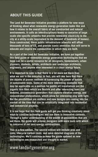
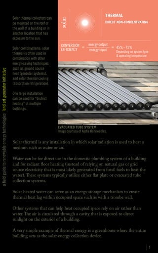
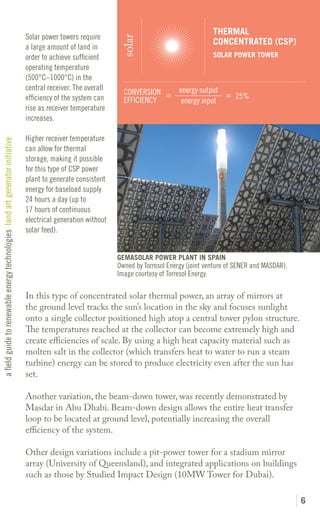
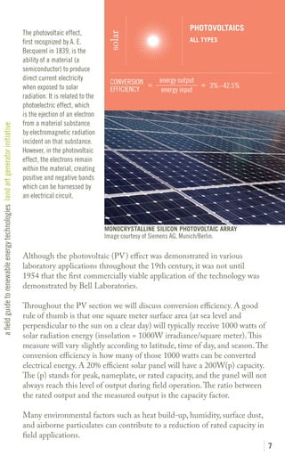
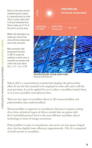
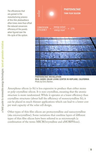
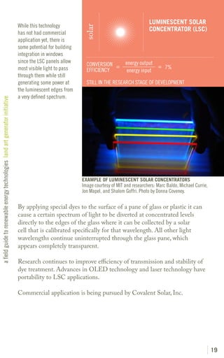
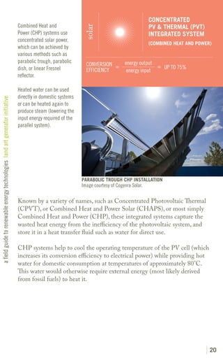
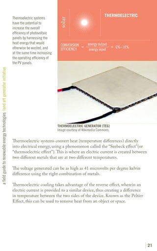
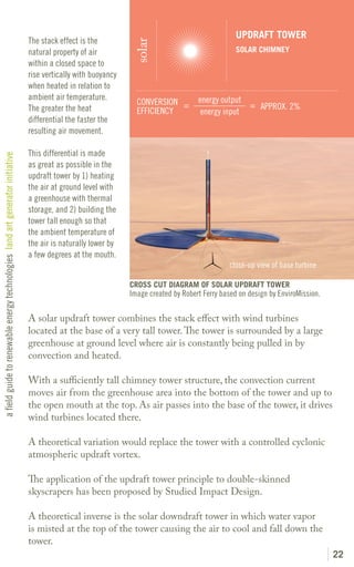
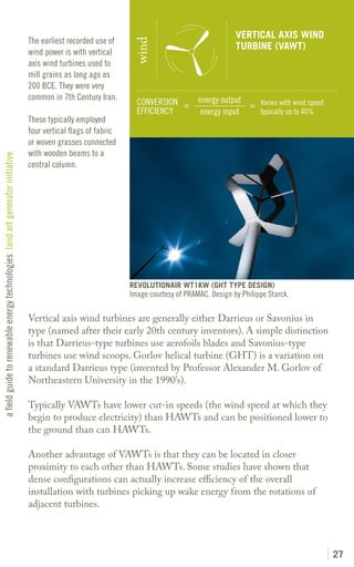
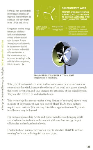
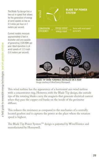
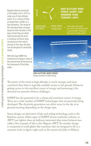
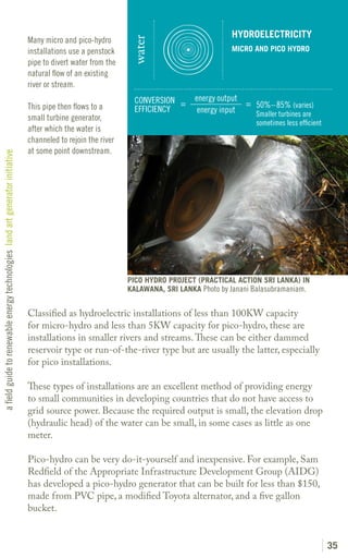
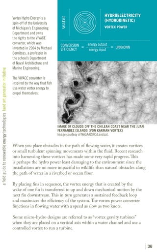
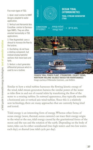
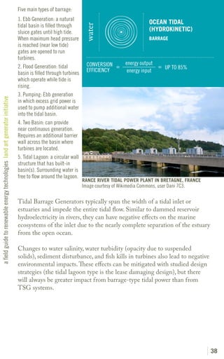
solar


        a field guide
wind


        to renewable
        energy
water


        technologies
bio


        land art generator initiative
        ROBERT FERRY + ELIZABETH MONOIAN
other
ABOUT THIS GUIDE

The Land Art Generator Initiative provides a platform for new ways
of thinking about what renewable energy generation looks like and
how it relates to the overall fabric of our constructed and natural
environments. It calls on interdisciplinary teams to conceive of large
scale site-specific artworks that provide renewable electricity to the
city at a utility-scale (equivalent to the demand of hundreds of homes).
Once constructed, these public infrastructure artworks will offset
thousands of tons of CO2 and provide iconic amenities that will serve to
educate and inspire the communities in which they are built.

As a part of the Land Art Generator Initiative, we have put together
this field guide of renewable energy generation technologies that we
hope can be a useful resource for all designers, homeowners, urban
planners, students, artists, architects and landscape architects,
engineers, and anyone else interested in a clean energy future.

It is important to note is that there is a lot more out there than
what we see in the everyday. In fact, you will see here that there
are dozens of proven methods of harnessing the power of nature
in sustainable ways. Some of the more interesting examples that
may be applicable as a medium for public art installations are the
organic thin films which are flexible and offer interesting hues and
textures, piezoelectric generators that capture vibration energy, and
concentrated photovoltaics, which allow for interesting play with light.
But the possibilities are endless and new designs are coming into the
market all the time that can be artistically integrated into residential
and commercial projects.

It is our hope that this field guide will get you thinking creatively about
ways to combine technologies and use them in innovative contexts.
Through a better understanding of the wealth of possibilities that are
out there, the guide will provide designers with more tools with which
to conceive of net zero energy constructions.

This is a first edition. The second edition will include pros and
cons, lifecycle carbon costs, and more detailed diagrams of the
technologies. We’ll continue to keep the guide updated as new
technologies are researched and brought to market.


www.landartgenerator.org
THERMAL
                                                                               Solar thermal collectors can


                                                                                                               solar
                                                                               be mounted on the roof or                                       DIRECT NON-CONCENTRATING
                                                                               the wall of a building or in
                                                                               another location that has
                                                                               exposure to the sun.
                                                                                                                CONVERSION =       energy output
                                                                               Solar combisystems: solar                                         = 45%–75%
                                                                                                                EFFICIENCY          energy input   Depending on system type
                                                                               thermal is often used in
                                                                                                                                                     & operating temperature
                                                                               combination with other
                                                                               energy-saving techniques
                                                                               such as ground source
a field guide to renewable energy technologies land art generator initiative


                                                                               heat (geosolar systems),
                                                                               and solar thermal cooling
                                                                               (absorption refrigeration).

                                                                               One large installation
                                                                               can be used for “district
                                                                               heating” of multiple
                                                                               buildings.


                                                                                                              EVACUATED TUBE SYSTEM
                                                                                                              Image courtesy of Alpha Renewables.

                                                                               Solar thermal is any installation in which solar radiation is used to heat a
                                                                               medium such as water or air.

                                                                               Water can be for direct use in the domestic plumbing system of a building
                                                                               and for radiant floor heating (instead of relying on natural gas or grid
                                                                               source electricity that is most likely generated from fossil fuels to heat the
                                                                               water). These systems typically utilize either flat plate or evacuated tube
                                                                               collection systems.

                                                                               Solar heated water can serve as an energy storage mechanism to create
                                                                               thermal heat lag within occupied space such as with a trombe wall.

                                                                               Other systems that can help heat occupied space rely on air rather than
                                                                               water. The air is circulated through a cavity that is exposed to direct
                                                                               sunlight on the exterior of a building.

                                                                               A very simple example of thermal energy is a greenhouse where the entire
                                                                               building acts as the solar energy collection device.

                                                                                                                                                                               1
THERMAL
                                                                               A defining characteristic


                                                                                                                  solar
                                                                               of a highly saline body of                                           SOLAR POND (SALTWATER)
                                                                               water is that it naturally
                                                                               stratifies into three layers of
                                                                               salinity. At the surface is a
                                                                               layer of low salinity and at                             energy output
                                                                                                                   CONVERSION =                       = 10%
                                                                               the bottom is a layer of very       EFFICIENCY            energy input
                                                                               high salinity. In between
                                                                               there is an intermediate
                                                                               insulating layer that keeps
                                                                               a heat exchange convention
a field guide to renewable energy technologies land art generator initiative


                                                                               cycle from forming.

                                                                               When exposed to solar
                                                                               radiation, heat is trapped in
                                                                               the bottom of the salt water
                                                                               pond where temperatures
                                                                               can reach nearly 100°C
                                                                               while water at the surface
                                                                               is 30°C.


                                                                                                                 EL PASO SOLAR POND
                                                                                                                 Image courtesy of the Texas State Energy Conservation Office.
                                                                                                                 Photo by Herb Hein.

                                                                               The heat that is trapped at the bottom of a saltwater pond can be harnessed
                                                                               to power an organic Rankine cycle turbine or a Stirling engine, both
                                                                               of which convert heat into electricity without steam (does not require
                                                                               temperatures in excess of H2O boiling point).

                                                                               Via the Organic Rankine Cycle (ORC), water is piped to an evaporator
                                                                               coil that heats a low-boiling-point fluid to pressurized vapor, driving a
                                                                               turbine. The vapor then passes to a condenser, where water from the top
                                                                               layer of the pond is used to cool the fluid back into liquid form after which
                                                                               it is then pumped back to the evaporator (with energy from a PV panel
                                                                               on-site).

                                                                               Because salt water is an excellent thermal heat sink, the solar pond
                                                                               produces electricity 24 hours per day regardless of weather conditions.
                                                                               Efficiency is greater in climates that receive higher average solar irradiance.


                                                                                                                                                                                 2
THERMAL
                                                                               CSP (concentrated solar


                                                                                                               solar
                                                                                                                                               CONCENTRATED (CSP)
                                                                               power) plants in operation
                                                                               in the USA as of 2010 met                                       PARABOLIC TROUGH
                                                                               the needs of over 350,000
                                                                               people and displaced the
                                                                               equivalent of 2.3 million                           energy output
                                                                                                                CONVERSION =                     = 25%
                                                                               barrels of oil annually.         EFFICIENCY          energy input

                                                                               Utility-scale CSP typically
                                                                               requires large tracts of
                                                                               land, but “Micro CSP”
a field guide to renewable energy technologies land art generator initiative


                                                                               systems can be designed
                                                                               for installation on building
                                                                               rooftops.


                                                                                                              SEGS POWER PLANT AT KRAMER JUNCTION IN THE MOJAVE DESERT
                                                                                                              Owned and operated by FPL Energy. Image via Desertec-UK.

                                                                               One of the most common types of solar power systems in application for
                                                                               utility-scale electricity generation, the concentrated parabolic trough design
                                                                               consists of a series of long, highly polished parabolic reflecting surfaces that
                                                                               focuses sunlight onto an absorber tube running along the focal point of the
                                                                               parabola.

                                                                               A heat transfer fluid (typically an oil) runs through the tube and is heated
                                                                               to approximately 400°C to provide the thermal energy required to run a
                                                                               steam turbine.

                                                                               The parabolic shape of the reflector allows the troughs to be oriented on a
                                                                               north-south axis and track the sun in only one rotational axis from east to
                                                                               west each day.

                                                                               Highly polished metals are often used as the reflector material since
                                                                               parabolic curved mirrors can be complex to manufacture.


                                                                                                                                                                         3
THERMAL
                                                                               Fresnel geometry allows flat                                     CONCENTRATED (CSP)


                                                                                                                solar
                                                                               surfaces to act in a way that
                                                                                                                                                LINEAR FRESNEL REFLECTOR
                                                                               mimics convex or concave                                         (LFR OR CLFR)
                                                                               mirror or lens optics.

                                                                               It was originally developed                           energy output
                                                                                                                 CONVERSION =                      = 20%
                                                                               by French physicist               EFFICIENCY           energy input
                                                                               Augustin-Jean Fresnel for
                                                                               use in lighthouses.
a field guide to renewable energy technologies land art generator initiative


                                                                               In a Fresnel reflector, a
                                                                               parabolic mirror is simulated
                                                                               in a segmented or “Fresnel”
                                                                               arrangement of flat mirrors.


                                                                                                               KIMBERLINA POWER PLANT IN BAKERSFIELD, CALIFORNIA
                                                                                                               Image courtesy of AREVA Solar.

                                                                               Linear Fresnel Reflectors (LFR) use long, thin segments of flat mirrors to
                                                                               focus sunlight onto a fixed absorber located at a common focal point of the
                                                                               reflectors. Absorbers in LFR often contain multiple heat transfer tubes.

                                                                               Similar to the more common parabolic trough, this single-axis tracking
                                                                               concentrated reflector system heats up a transfer fluid which in turn heats
                                                                               water to run a steam turbine (in the case of LFR, temperatures in the
                                                                               transfer fluid can reach 750°C although 300°C is more common). One
                                                                               advantage of LFR is that the reflector mirrors are flat rather than parabolic
                                                                               in shape, which makes for a simpler mirror manufacturing process.

                                                                               Systems can be set up to focus sunlight onto a single absorber (LFR) or
                                                                               onto multiple absorbers which is referred to as a Compact Linear Fresnel
                                                                               Reflector (CLFR) system. CLFR design is obtained by alternating the
                                                                               angle of each reflector. This can lead to greater energy conversion efficiency
                                                                               of the overall system.


                                                                                                                                                                           4
THERMAL
                                                                               The Stirling Engine is a


                                                                                                               solar
                                                                                                                                                CONCENTRATED (CSP)
                                                                               type of external combustion
                                                                               engine of the reciprocating                                      DISH STIRLING
                                                                               piston variety. It is named
                                                                               after Robert Stirling, who
                                                                               in 1816 invented the closed-                         energy output
                                                                                                                CONVERSION =                      = 31.25%
                                                                               cycle air engine.                EFFICIENCY           energy input

                                                                               The engine works on
                                                                               the principle that gas
                                                                               expands as its temperature
a field guide to renewable energy technologies land art generator initiative


                                                                               increases. Expansion and
                                                                               contraction cycles will move
                                                                               a piston back and forth
                                                                               within a closed chamber.
                                                                               A magnetic piston moving
                                                                               through an electromagnetic
                                                                               field becomes a linear
                                                                               alternator, thus producing
                                                                               electric current.


                                                                                                              JVP PHASE II DISH STIRLING ENGINE 25 KILOWATT SYSTEM
                                                                                                              Image courtesy of the US National Renewable Energy Lab (NREL).
                                                                                                              Photo by David Parsons.

                                                                               Dish type collectors look sort of like television satellite receivers in their
                                                                               shape. They are parabolic, but unlike a linear parabola that concentrates
                                                                               along an axis, these are dish parabolas that concentrate light onto a single
                                                                               point. They can be one large dish, or a polar array of smaller reflectors as in
                                                                               the photo above.

                                                                               They must rotate on a dual-axis to track the sun’s position in the sky. At
                                                                               the single focal point is typically situated a Stirling Engine which converts
                                                                               heat into mechanical energy with high efficiency. The mechanical energy is
                                                                               then converted to electricity with a dynamo.

                                                                               This type of concentrated solar thermal electricity installation rivals the
                                                                               best efficiencies of concentrated photovoltaic systems per similar land
                                                                               area and relies on more simple mechanical technologies as opposed to
                                                                               semiconductors and microelectronics.

                                                                               Some CPV installations also utilize dish type collectors (refer to page 18).

                                                                                                                                                                               5
THERMAL
                                                                               Solar power towers require


                                                                                                                solar
                                                                                                                                                 CONCENTRATED (CSP)
                                                                               a large amount of land in
                                                                               order to achieve sufficient                                       SOLAR POWER TOWER
                                                                               operating temperature
                                                                               (500°C–1000°C) in the
                                                                               central receiver. The overall                         energy output
                                                                                                                 CONVERSION =                      = 25%
                                                                               efficiency of the system can      EFFICIENCY           energy input
                                                                               rise as receiver temperature
                                                                               increases.

                                                                               Higher receiver temperature
a field guide to renewable energy technologies land art generator initiative


                                                                               can allow for thermal
                                                                               storage, making it possible
                                                                               for this type of CSP power
                                                                               plant to generate consistent
                                                                               energy for baseload supply
                                                                               24 hours a day (up to
                                                                               17 hours of continuous
                                                                               electrical generation without
                                                                               solar feed).


                                                                                                               GEMASOLAR POWER PLANT IN SPAIN
                                                                                                               Owned by Torresol Energy (joint venture of SENER and MASDAR).
                                                                                                               Image courtesy of Torresol Energy.

                                                                               In this type of concentrated solar thermal power, an array of mirrors at
                                                                               the ground level tracks the sun’s location in the sky and focuses sunlight
                                                                               onto a single collector positioned high atop a central tower pylon structure.
                                                                               The temperatures reached at the collector can become extremely high and
                                                                               create efficiencies of scale. By using a high heat capacity material such as
                                                                               molten salt in the collector (which transfers heat to water to run a steam
                                                                               turbine) energy can be stored to produce electricity even after the sun has
                                                                               set.

                                                                               Another variation, the beam-down tower, was recently demonstrated by
                                                                               Masdar in Abu Dhabi. Beam-down design allows the entire heat transfer
                                                                               loop to be located at ground level, potentially increasing the overall
                                                                               efficiency of the system.

                                                                               Other design variations include a pit-power tower for a stadium mirror
                                                                               array (University of Queensland), and integrated applications on buildings
                                                                               such as those by Studied Impact Design (10MW Tower for Dubai).

                                                                                                                                                                               6
PHOTOVOLTAICS
                                                                               The photovoltaic effect,


                                                                                                                  solar
                                                                               first recognized by A. E.                                           ALL TYPES
                                                                               Becquerel in 1839, is the
                                                                               ability of a material (a
                                                                               semiconductor) to produce
                                                                               direct current electricity                              energy output
                                                                                                                   CONVERSION =                      = 3%– 42.5%
                                                                               when exposed to solar               EFFICIENCY           energy input
                                                                               radiation. It is related to the
                                                                               photoelectric effect, which
                                                                               is the ejection of an electron
                                                                               from a material substance
a field guide to renewable energy technologies land art generator initiative


                                                                               by electromagnetic radiation
                                                                               incident on that substance.
                                                                               However, in the photovoltaic
                                                                               effect, the electrons remain
                                                                               within the material, creating
                                                                               positive and negative bands
                                                                               which can be harnessed by
                                                                               an electrical circuit.


                                                                                                                 MONOCRYSTALLINE SILICON PHOTOVOLTAIC ARRAY
                                                                                                                 Image courtesy of Siemens AG, Munich/Berlin.

                                                                               Although the photovoltaic (PV) effect was demonstrated in various
                                                                               laboratory applications throughout the 19th century, it was not until
                                                                               1954 that the first commercially viable application of the technology was
                                                                               demonstrated by Bell Laboratories.

                                                                               Throughout the PV section we will discuss conversion efficiency. A good
                                                                               rule of thumb is that one square meter surface area (at sea level and
                                                                               perpendicular to the sun on a clear day) will typically receive 1000 watts of
                                                                               solar radiation energy (insolation = 1000W irradiance/square meter). This
                                                                               measure will vary slightly according to latitude, time of day, and season. The
                                                                               conversion efficiency is how many of those 1000 watts can be converted
                                                                               electrical energy. A 20% efficient solar panel will have a 200W(p) capacity.
                                                                               The (p) stands for peak, nameplate, or rated capacity, and the panel will not
                                                                               always reach this level of output during field operation. The ratio between
                                                                               the rated output and the measured output is the capacity factor.

                                                                               Many environmental factors such as heat build-up, humidity, surface dust,
                                                                               and airborne particulates can contribute to a reduction of rated capacity in
                                                                               field applications.
                                                                                                                                                                   7
PHOTOVOLTAIC
                                                                               Silicon is the most common


                                                                                                                  solar
                                                                               metalloid found in nature.                                      CRYSTALLINE SILICON WAFER
                                                                               It is typically found as silica
                                                                               (SiO2) in sands rather than
                                                                               in its pure elemental form.
                                                                               Silicon makes up 27.7% of                               energy output
                                                                                                                   CONVERSION =                      = 18%–23%
                                                                               the earth’s crust by mass.          EFFICIENCY           energy input

                                                                               Molten salt electrolysis can
                                                                               create pure silicon from
                                                                               silica with low energy input
a field guide to renewable energy technologies land art generator initiative


                                                                               and no CO2 emissions.

                                                                               More commonly, high
                                                                               temperature furnaces
                                                                               (1,900°C) create the
                                                                               condition in which silica is
                                                                               converted via reaction with
                                                                               carbon into pure silicon.
                                                                               SiO2 + 2 C -> Si + 2 CO


                                                                                                                 POLYCRYSTALLINE SILICON SOLAR PANEL
                                                                                                                 Photo by Scott Robinson.

                                                                               Silicon (Si) is a semiconductor material that displays the photovoltaic
                                                                               effect. It was the first material to be employed in solar cells and is still the
                                                                               most prevalent. It can be applied for use in either a crystalline (wafer) form,
                                                                               or in a non-crystalline (amorphous) form.

                                                                               There are two types of crystalline silicon (c-Si): monocrystalline and
                                                                               polycrystalline (aka multicrystalline).

                                                                               Monocrystalline is expensive to manufacture (because it requires cutting
                                                                               slices from cylindrical ingots of silicon crystals that are grown with
                                                                               the Czochralski process) but it is the most efficient crystalline silicon
                                                                               technology in terms of energy conversion.

                                                                               Polycrystalline is easier to manufacture and can be cut into square shaped
                                                                               slices, but has slightly lower efficiency (approximately -5%). It is comprised
                                                                               of small crystals or crystallites.


                                                                                                                                                                           8
PHOTOVOLTAIC
                                                                               The efficiencies that


                                                                                                               solar
                                                                               are gained in the                                                THIN FILM SILICON
                                                                               manufacturing process
                                                                               of thin film photovoltaics
                                                                               often times more than offset
                                                                               the reduced conversion                                  energy output
                                                                                                                CONVERSION =                         = 12%
                                                                               efficiency of the panels         EFFICIENCY              energy input
                                                                               when figured over the
                                                                               life-cycle of the system.
a field guide to renewable energy technologies land art generator initiative


                                                                                                              PHOTOVOLTAIC INSTALLATION
                                                                                                              REAL GOODS SOLAR LIVING CENTER IN HOPLAND, CALIFORNIA
                                                                                                              Photo by Chris Benton.

                                                                               Amorphous silicon (a-Si) is less expensive to produce than either mono
                                                                               or poly-crystalline silicon. It is non-crystalline, meaning that the atomic
                                                                               structure is more randomized. While it operates at a lower efficiency than
                                                                               crystalline structures (about half the efficiency of monocrystalline Si), it
                                                                               can be placed in much thinner applications which can lead to a lower cost
                                                                               per watt capacity of the solar cell design.

                                                                               Other types of thin film silicon are protocrystalline and nanocrystalline
                                                                               (aka microcrystalline). Some variations that combine layers of different
                                                                               types of thin film silicon have been referred to as micromorph (a
                                                                               combination of the terms MICROcrystalline and aMORPHous).


                                                                                                                                                                      9
PHOTOVOLTAIC
                                                                               The levelized cost of energy


                                                                                                               solar
                                                                               for non-silicon systems                                          THIN FILM NON-SILICON
                                                                               when compared to silicon-
                                                                               based PV depends greatly
                                                                               on the global market cost
                                                                               of silicon at the time of                            energy output
                                                                                                                CONVERSION =                      = 16%–20%
                                                                               manufacture.                     EFFICIENCY           energy input

                                                                               Silicon is more abundant in
                                                                               nature than CIGS or CdTe
                                                                               raw materials. However,
a field guide to renewable energy technologies land art generator initiative


                                                                               during periods of high
                                                                               global demand, silicon can
                                                                               sometimes cost more as a
                                                                               raw material.

                                                                               Each semi-conductor
                                                                               material captures light
                                                                               energy most efficiently
                                                                               across a limited wavelength
                                                                               spectrum.

                                                                                                              SEMPRA GENERATION’S CDTE COPPER MOUNTAIN SOLAR FACILITY
                                                                                                              Image courtesy of Sempra U.S. Gas & Power, LLC.

                                                                               As an alternative to silicon (Si), other semiconductor materials can be used
                                                                               for thin film solar cells. They have been proven to have greater efficiency
                                                                               than thin film amorphous silicon.

                                                                               Copper-Indium Gallium Selenide (CIGS) has a conversion efficiency
                                                                               of about 20%. It can be manufactured to be very thin due to its high
                                                                               absorption coefficient.

                                                                               Cadmium Telluride (CdTe) has a conversion efficiency of about 16% and
                                                                               potentially offers cost advantages over CIGS.

                                                                               The company Nanosolar has developed
                                                                               a method of printing CIGS onto thin
                                                                               foil substrates with nanoparticle inks
                                                                               and roll-to-roll manufacturing, which
                                                                               allows for flexible thin film panels while
                                                                               reducing production costs.

                                                                                                                                            Image courtesy of Nanosolar.
                                                                                                                                                                           10
PHOTOVOLTAIC
                                                                               Also called “tandem cells,”


                                                                                                                  solar
                                                                               these specialized type of                                             THIN FILM MULTIJUNCTION
                                                                               solar cells have been limited
                                                                               to use in aerospace, CPV, or
                                                                               other unique applications
                                                                               due to their complexity and                              energy output
                                                                                                                   CONVERSION =                       = 25%– 45%
                                                                               expense.                            EFFICIENCY            energy input

                                                                               Multijunction cells are
                                                                               capable of achieving high
                                                                               conversion efficiencies
a field guide to renewable energy technologies land art generator initiative


                                                                               because they are able to
                                                                               capture electrons within
                                                                               multiple wavelengths of
                                                                               light. Single junction cells
                                                                               are limited to the energy
                                                                               within a partial spectrum,
                                                                               the remaining light either
                                                                               reflecting off or being lost to
                                                                               heat energy.


                                                                                                                 MULTIJUNCTION CELL BY SOLAR JUNCTION
                                                                                                                 Image courtesy of Solar Junction.

                                                                               Multijunction cells take advantage of multiple materials, each of which
                                                                               best capture a particular light wavelength (color spectrum) for solar-to-
                                                                               electricity conversion. This can lead to very high conversion efficiencies,
                                                                               even above 40%.

                                                                               The technology was first developed for use in space explorations such as
                                                                               the Mars rover missions, and is still used for space applications. Because
                                                                               of the expense of manufacture, terrestrial commercial application has been
                                                                               generally limited to CPV systems (refer to page 18).

                                                                               Different techniques use different substrate materials and can be either
                                                                               two-junction or three-junction. Some substrate materials that are used
                                                                               are: Gallium arsenide, Germanium, and Indium phosphide. Because the
                                                                               thin film is deposited (epitaxially) onto a monocrystalline substrate, the
                                                                               applied layers take on the lattice structure of the substrate crystal while
                                                                               maintaining thin film properties.


                                                                                                                                                                               11
PHOTOELECTROCHEMICAL
                                                                               One of the technical


                                                                                                              solar
                                                                                                                                                CELL (PEC)
                                                                               obstacles to greater
                                                                               proliferation of PEC-type
                                                                               electrolysis for hydrogen
                                                                               generation is the
                                                                               corrosive effect of the                              energy output
                                                                                                               CONVERSION =                       = 10%
                                                                               electrolyte solution on the     EFFICIENCY            energy input
                                                                               semiconductor anode.
a field guide to renewable energy technologies land art generator initiative


                                                                                                             PROOF-OF-CONCEPT BY PROFESSOR MICHAEL STRANO ET AL.
                                                                                                             Image courtesy of MIT. Photo by Patrick Gillooly.

                                                                               These are solar cells that transform solar energy directly into electrical
                                                                               energy. Instead of using a solid-state semiconductor as the light absorbing
                                                                               material, PECs use a electrolyte material (typically a fluid). A circuit is
                                                                               created via a semiconducting anode and a metal cathode which are both in
                                                                               contact with the electrolyte.

                                                                               One type of PEC is the DSSC (dye-sensitized solar cell). More about
                                                                               DSSC can be found on page 13.

                                                                               Other types can be used to harness solar energy directly for purposes of
                                                                               electrolysis to create hydrogen—a stored fuel. In this system, water acts
                                                                               as the electrolyte solution. Hydrogen and oxygen form around the anode
                                                                               when exposed to sunlight. The resulting hydrogen can be stored and used
                                                                               to generate electricity in fuel cells. An example of this technology in action
                                                                               is the work by Rose Street Labs Energy (RSLE) scientists at Phoenix,
                                                                               Arizona.


                                                                                                                                                                   12
PHOTOVOLTAIC
                                                                               Because of the existence of


                                                                                                                solar
                                                                               liquid electrolyte within the                                  THIN FILM
                                                                                                                                              DYE-SENSITIZED (DSSC)
                                                                               DSSC cells, the temperature
                                                                               must be maintained within
                                                                               certain bounds.
                                                                                                                 CONVERSION =         energy output
                                                                               The liquid also acts as a                                            = 9%–11%
                                                                                                                 EFFICIENCY            energy input
                                                                               solvent over time. This,
                                                                               and the volatility of the
                                                                               dyes under UV light mean
                                                                               that details of the material
a field guide to renewable energy technologies land art generator initiative


                                                                               housing assembly are
                                                                               critical.

                                                                               Research is underway to
                                                                               replace the liquid with a
                                                                               solid material.


                                                                                                               DYESOL SERIES INTERCONNECT GLASS MODULE
                                                                                                               Image courtesy of Dyesol.

                                                                               Techniques for creating dye-sensitized solar cells (DSSC) are simple and
                                                                               the materials are very low cost, but the conversion efficiency is also below
                                                                               that of solid-state semiconductor technologies (DSSC is the most efficient
                                                                               of the “third generation” thin films).

                                                                               This technique was invented in 1991 by Michael Grätzel and Brian
                                                                               O’Regan at EPFL. The DSSC solar cell is alternatively known as the
                                                                               Grätzel cell.

                                                                               They have the characteristic of being semi-transparent, flexible, and are
                                                                               very durable. They also function comparatively better than other PV
                                                                               technologies in low light levels and indirect light.

                                                                               Because they are relatively inexpensive to produce they have one of the
                                                                               lowest price/performance ratios, and despite their lower conversion
                                                                               efficiency are therefore competitive with conventional energy in terms of
                                                                               levelized cost (price per KWh over the lifetime of the installation).


                                                                                                                                                                      13
PHOTOVOLTAIC
                                                                               Organic thin film has some


                                                                                                              solar
                                                                               advantages over silicon or                                       THIN FILM ORGANIC
                                                                                                                                                PHOTOVOLTAIC CELL (OPVC)
                                                                               other semi-conductor type                                        OR POLYMER SOLAR CELL
                                                                               solar cells.

                                                                               Its organic and plastic                             energy output
                                                                                                               CONVERSION =                      = 3%– 8%
                                                                               nature means that it can        EFFICIENCY           energy input
                                                                               be easily fabricated into
                                                                               flexible shapes.

                                                                               It functions well under low
a field guide to renewable energy technologies land art generator initiative


                                                                               light conditions and at
                                                                               angles to the sun that are
                                                                               off from perpendicular such
                                                                               as vertical walls.

                                                                               Its translucency means
                                                                               that it can also be applied
                                                                               to windows and other light
                                                                               transmitting surfaces.


                                                                                                             KONARKA “POWER PLASTIC”
                                                                                                             Image courtesy of Konarka Technologies, Inc.

                                                                               OPVC (or OPV) uses organic polymers to absorb sunlight and transmit
                                                                               electrical charges. Organic PV can be manufactured in solutions that can
                                                                               be painted or rolled onto proper substrate materials. They can be produced
                                                                               at very low cost in comparison with other PV technologies because they
                                                                               can take advantage of roll-to-roll production techniques in which the
                                                                               organic photovoltaic system is “printed” onto a long continuous sheet of
                                                                               substrate material.

                                                                               Current OPVC technology has a conversion efficiency of only up to 8%.
                                                                               But its low cost of production, its flexibility, and its good performance
                                                                               in lower level and indirect light make it an attractive option for some
                                                                               applications.

                                                                               Examples of OPVC can already be seen in applications where patches
                                                                               of PV material is sewn into fabric such as in backpacks, laptop cases, and
                                                                               jackets. The energy generated by these products is sufficient to charge
                                                                               portable electronic devices.


                                                                                                                                                                           14
PHOTOVOLTAIC
                                                                               One application of 3D


                                                                                                               solar
                                                                                                                                                 3D CELLS
                                                                               concepts to photovoltaics is
                                                                               the research that is being
                                                                               done at Georgia Tech. They
                                                                               are coating optical fibre
                                                                               cable with dye-sensitized                            energy output
                                                                                                                CONVERSION =                      = 26%–50%
                                                                               solar cells in an effort to      EFFICIENCY           energy input
                                                                               increase the amount of light
                                                                               transmission to photovoltaic     STILL IN THE RESEARCH STAGE OF DEVELOPMENT
                                                                               material over any given
                                                                               surface area exposed to
a field guide to renewable energy technologies land art generator initiative


                                                                               the sun.

                                                                               Another project at CalTech
                                                                               also shows promise with
                                                                               a flexible array of light-
                                                                               absorbing silicon microwires
                                                                               and light-reflecting metal
                                                                               nanoparticles embedded in
                                                                               a polymer.


                                                                                                              A PROTOTYPE 3D SOLAR CELL CREATED AT GEORGIA TECH
                                                                                                              Image courtesy of Georgia Tech University and Regents Professor
                                                                                                              Zhong Lin Wang. Photo by Gary Meek.

                                                                               These solar cells can utilize any of the various PV material designs. The
                                                                               initial focus by the company 3D Solar has been on integrating conventional
                                                                               silicon-based PV as the photovoltaic material. The technological innovation
                                                                               lies in the initial capture of light at the surface of the solar panel.

                                                                               Whereas a standard panel solar cell will typically reflect 20%–30% of the
                                                                               light that strikes its surface, a 3D cell relies on a geometric structure that
                                                                               can recapture the reflected light onto adjacent PV surfaces, thus increasing
                                                                               the efficiency of the entire system over the same surface area of installation.

                                                                               Use of multijunction technology in combination with 3D solar cell
                                                                               geometry has the potential to see applications in CPV systems with an
                                                                               energy conversion efficiency of 50% or greater.

                                                                               Plasmonic solar cells (PSC) use nanoparticles on the surface of a solar cell
                                                                               to scatter and trap more light within the cell.


                                                                                                                                                                                15
PHOTOVOLTAIC
                                                                               Because infrared and


                                                                                                                solar
                                                                                                                                                  INFRARED AND UV
                                                                               ultraviolet light is outside
                                                                               of the spectrum of human
                                                                               sight, these type of
                                                                               photovoltaic panels could
                                                                               function very well as                                  energy output
                                                                                                                 CONVERSION =                       = UP TO 90%
                                                                               window surfaces, while still      EFFICIENCY            energy input
                                                                               letting in the entire visible
                                                                               spectrum and reducing             STILL IN THE RESEARCH STAGE OF DEVELOPMENT
                                                                               internal building heat gain
                                                                               at the same time.
a field guide to renewable energy technologies land art generator initiative


                                                                               Unfortunately, this
                                                                               technology is still mostly
                                                                               in the research stage and
                                                                               is not yet commercially
                                                                               available.

                                                                                                                                                                    2μm


                                                                                                               NANOANTENNA STRUCTURE CAPTURES IR SPECTRUM RADIATION
                                                                                                               Image courtesy of Idaho National Laboratory.

                                                                               Experimental research is ongoing to develop methods of converting
                                                                               infrared and UV light into electrical power.

                                                                               Since infrared solar radiation energy is radiated back from the earth
                                                                               during the night, a system to capture it could potentially provide energy
                                                                               24 hours a day. A team of researchers at Idaho National Laboratory, the
                                                                               University of Missouri, and the University of Colorado are working to
                                                                               develop nanoantennas (nantenna) that can collect both solar heat energy
                                                                               and industrial waste heat energy. The flexible film would be able to convert
                                                                               up to 90% of available light across multiple spectrums.

                                                                               Since UV and infrared light is beyond the visible spectrum, solar panels
                                                                               that focus on these spectrums can let visible light through while still
                                                                               harnessing solar energy. Japan’s National Institute of Advanced Industrial
                                                                               Science and Technology has shown proof of concept applications of this
                                                                               type of technology.


                                                                                                                                                                      16
THERMOPHOTOVOLTAIC
                                                                               Potential exists with TPV to


                                                                                                                  solar
                                                                                                                                                  (TPV)
                                                                               see significant increases in
                                                                               the overall efficiency of solar
                                                                               power systems by converting
                                                                               residual heat energy that is
                                                                               otherwise wasted.                                       energy output
                                                                                                                   CONVERSION =                      = Greater than 50%
                                                                                                                   EFFICIENCY           energy input   PV + TPV (theoretical)
a field guide to renewable energy technologies land art generator initiative


                                                                                                                 Image courtesy of IMEC.


                                                                               TPV converts heat energy directly into electricity via photons. A TPV
                                                                               system consists of a thermal emitter and a photovoltaic diode. For the most
                                                                               efficient operation, the temperature of the thermal emitter should be about
                                                                               1000°C above the temperature of the photovoltaic diode cell, but some
                                                                               amount of energy could be created from smaller differences in temperature.

                                                                               TPV employs photovoltaic technology but does not necessarily rely on the
                                                                               sun as the emitter of the photon energy.


                                                                                                                                                                                17
PHOTOVOLTAIC
                                                                               Some CPV systems employ


                                                                                                                  solar
                                                                               parabolic troughs that direct                                        CONCENTRATED PV (CPV)
                                                                                                                                                    LOW (LCPV) = 2–100 SUNS
                                                                               sunlight onto a linear solar
                                                                                                                                                    HIGH (HCPV) = 300–1000 SUNS
                                                                               cell with parabolic troughs.

                                                                               Another design is the Total                              energy output
                                                                               Spectrum Collector which            CONVERSION =                       = UP TO 42%
                                                                                                                   EFFICIENCY            energy input
                                                                               separates light with a prism
                                                                               into different spectrums best
                                                                               suited to different solar cell
                                                                               types.
a field guide to renewable energy technologies land art generator initiative


                                                                               Still another variation is
                                                                               the mylar balloon design
                                                                               developed by Cool Earth
                                                                               in which a CPV solar cell
                                                                               at the upper side of a
                                                                               clear hemisphere receives
                                                                               concentrated sunlight from
                                                                               the lower hemisphere which is
                                                                               highly reflective on the inside
                                                                               surface.
                                                                                                                 CONCENTRATED PV
                                                                                                                 Image courtesy of SolFocus, Inc.

                                                                               CPV employs photovoltaic cells, but rather than rely on the standard
                                                                               intensity of naturally occurring solar radiation energy the CPV system
                                                                               concentrates the sunlight and directs a magnified beam onto a smaller
                                                                               area solar cell specifically designed to handle the greater energy and heat.
                                                                               Because the solar cell can be much smaller, the amount of semiconductor
                                                                               material required is far less for the same watt capacity output when
                                                                               compared to non-concentrated PV systems. This can greatly reduce the
                                                                               construction cost per watt capacity of the overall system. Because of the
                                                                               increased heat on the solar cell, CPV installations often require integration
                                                                               of heat sinks or other cooling apparatus.

                                                                               The magnification of the sunlight can be accomplished by a number of
                                                                               methods, the most common of which is a Fresnel lens. Other designs,
                                                                               such as that of SolFocus and Cool Earth, utilize reflectors. Nearly all CPV
                                                                               systems must track the sun’s movement across the sky in order to function
                                                                               properly. CPV can reach the greatest installed efficiencies of existing PV
                                                                               installations for utility-scale applications.


                                                                                                                                                                            18
LUMINESCENT SOLAR
                                                                               While this technology


                                                                                                              solar
                                                                                                                                                CONCENTRATOR (LSC)
                                                                               has not had commercial
                                                                               application yet, there is
                                                                               some potential for building
                                                                               integration in windows
                                                                               since the LSC panels allow                          energy output
                                                                                                               CONVERSION =                      = 7%
                                                                               most visible light to pass      EFFICIENCY           energy input
                                                                               through them while still
                                                                               generating some power at        STILL IN THE RESEARCH STAGE OF DEVELOPMENT
                                                                               the luminescent edges from
                                                                               a very defined spectrum.
a field guide to renewable energy technologies land art generator initiative


                                                                                                             EXAMPLE OF LUMINESCENT SOLAR CONCENTRATORS
                                                                                                             Image courtesy of MIT and researchers: Marc Baldo, Michael Currie,
                                                                                                             Jon Mapel, and Shalom Goffri. Photo by Donna Coveney.

                                                                               By applying special dyes to the surface of a pane of glass or plastic it can
                                                                               cause a certain spectrum of light to be diverted at concentrated levels
                                                                               directly to the edges of the glass where it can be collected by a solar
                                                                               cell that is calibrated specifically for that wavelength. All other light
                                                                               wavelengths continue uninterrupted through the glass pane, which
                                                                               appears completely transparent.

                                                                               Research continues to improve efficiency of transmission and stability of
                                                                               dye treatment. Advances in OLED technology and laser technology have
                                                                               portability to LSC applications.

                                                                               Commercial application is being pursued by Covalent Solar, Inc.


                                                                                                                                                                                  19
CONCENTRATED
                                                                               Combined Heat and                                                 PV & THERMAL (PVT)


                                                                                                               solar
                                                                               Power (CHP) systems use                                           INTEGRATED SYSTEM
                                                                               concentrated solar power,
                                                                                                                                                 (COMBINED HEAT AND POWER)
                                                                               which can be achieved by
                                                                               various methods such as
                                                                               parabolic trough, parabolic                          energy output
                                                                                                                CONVERSION =                      = UP TO 75%
                                                                               dish, or linear Fresnel          EFFICIENCY           energy input
                                                                               reflector.

                                                                               Heated water can be used
                                                                               directly in domestic systems
a field guide to renewable energy technologies land art generator initiative


                                                                               or can be heated again to
                                                                               produce steam (lowering the
                                                                               input energy required of the
                                                                               parallel system).


                                                                                                              PARABOLIC TROUGH CHP INSTALLATION
                                                                                                              Image courtesy of Cogenra Solar.

                                                                               Known by a variety of names, such as Concentrated Photovoltaic Thermal
                                                                               (CPVT), or Combined Heat and Power Solar (CHAPS), or most simply
                                                                               Combined Heat and Power (CHP), these integrated systems capture the
                                                                               wasted heat energy from the inefficiency of the photovoltaic system, and
                                                                               store it in a heat transfer fluid such as water for direct use.

                                                                               CHP systems help to cool the operating temperature of the PV cell (which
                                                                               increases its conversion efficiency to electrical power) while providing hot
                                                                               water for domestic consumption at temperatures of approximately 80°C.
                                                                               This water would otherwise require external energy (most likely derived
                                                                               from fossil fuels) to heat it.


                                                                                                                                                                         20
THERMOELECTRIC
                                                                               Thermoelectric systems


                                                                                                              solar
                                                                               have the potential to
                                                                               increase the overall
                                                                               efficiency of photovoltaic
                                                                               panels by harnessing the
                                                                               heat energy that would                             energy output
                                                                                                               CONVERSION =                     = 6%–10%
                                                                               otherwise be wasted, and        EFFICIENCY          energy input
                                                                               at the same time increasing
                                                                               the operating efficiency of
                                                                               the PV panels.
a field guide to renewable energy technologies land art generator initiative


                                                                                                             THERMOELECTRIC GENERATOR (TEG)
                                                                                                             Image courtesy of Wikimedia Commons.

                                                                               Thermoelectric systems convert heat (temperature differences) directly
                                                                               into electrical energy, using a phenomenon called the “Seebeck effect”(or
                                                                               “thermoelectric effect”). This is where an electric current is created between
                                                                               two different metals that are at two different temperatures.

                                                                               The voltage generated can be as high as 41 microvolts per degree kelvin
                                                                               difference using the right combination of metals.

                                                                               Thermoelectric cooling takes advantage of the reverse effect, wherein an
                                                                               electric current is provided to a similar device, thus creating a difference
                                                                               in temperature between the two sides of the device. Known as the Peltier
                                                                               Effect, this can be used to remove heat from an object or space.


                                                                                                                                                                21
UPDRAFT TOWER
                                                                               The stack effect is the


                                                                                                                solar
                                                                               natural property of air                                            SOLAR CHIMNEY
                                                                               within a closed space to
                                                                               rise vertically with buoyancy
                                                                               when heated in relation to
                                                                               ambient air temperature.                              energy output
                                                                                                                 CONVERSION =                      = APPROX. 2%
                                                                               The greater the heat              EFFICIENCY           energy input
                                                                               differential the faster the
                                                                               resulting air movement.

                                                                               This differential is made
a field guide to renewable energy technologies land art generator initiative


                                                                               as great as possible in the
                                                                               updraft tower by 1) heating
                                                                               the air at ground level with
                                                                               a greenhouse with thermal
                                                                               storage, and 2) building the
                                                                               tower tall enough so that
                                                                               the ambient temperature of
                                                                               the air is naturally lower by
                                                                               a few degrees at the mouth.
                                                                                                                                                close-up view of base turbine

                                                                                                               CROSS CUT DIAGRAM OF SOLAR UPDRAFT TOWER
                                                                                                               Image created by Robert Ferry based on design by EnviroMission.

                                                                               A solar updraft tower combines the stack effect with wind turbines
                                                                               located at the base of a very tall tower. The tower is surrounded by a large
                                                                               greenhouse at ground level where air is constantly being pulled in by
                                                                               convection and heated.

                                                                               With a sufficiently tall chimney tower structure, the convection current
                                                                               moves air from the greenhouse area into the bottom of the tower and up to
                                                                               the open mouth at the top. As air passes into the base of the tower, it drives
                                                                               wind turbines located there.

                                                                               A theoretical variation would replace the tower with a controlled cyclonic
                                                                               atmospheric updraft vortex.

                                                                               The application of the updraft tower principle to double-skinned
                                                                               skyscrapers has been proposed by Studied Impact Design.

                                                                               A theoretical inverse is the solar downdraft tower in which water vapor
                                                                               is misted at the top of the tower causing the air to cool and fall down the
                                                                               tower.
                                                                                                                                                                                 22
SOLAR CHEMICAL
                                                                               Since the photosynthetic


                                                                                                               solar
                                                                               process removes CO2 from                                       ARTIFICIAL PHOTOSYNTHESIS
                                                                               the atmosphere, a highly
                                                                               efficient system in wide
                                                                               commercial application
                                                                               could produce energy at                             energy output
                                                                                                                CONVERSION =                     = UP TO 60%
                                                                               the same time as it could        EFFICIENCY          energy input
                                                                               help reduce atmospheric
                                                                               CO2, potentially bringing
                                                                               atmospheric levels down to
                                                                               below 350 parts per million.
a field guide to renewable energy technologies land art generator initiative


                                                                                                              Image courtesy of Wikimedia Commons.


                                                                               Some direct-to-hydrogen processes (refer to PEC technology on page
                                                                               12) are referred to as artificial photosynthesis, but they can also be more
                                                                               accurately described as photoelectrolysis.

                                                                               There are other types of technologies that closely mimic photosynthesis
                                                                               by using carbon dioxide and water along with sunlight in order to produce
                                                                               hydrogen using ruthenium as a chlorophyll substitute. Other systems using
                                                                               cobalt oxide aim to create synthetic fuels such as methanol or methane.

                                                                               Cyanobacteria (blue-green algae) can also be used to create hydrogen
                                                                               directly from sunlight, though the efficiency is lower.

                                                                               Researchers Andreas Mershin and Shuguang Zhang of MIT’s Center for
                                                                               Biomedical Engineering have shown how the actual molecules responsible
                                                                               for photosynthesis in plants (PS-I) can be inexpensively put to work in
                                                                               solar panels. Work continues to increase efficiency (presently 0.1%).

                                                                               Photodimerization and Photoisomerization are two other processes that
                                                                               are being investigated as methods of storing solar energy in usable forms.
                                                                                                                                                                          23
OTHER EXPERIMENTAL /


                                                                                                         solar
                                                                                                                                    THEORETICAL
a field guide to renewable energy technologies land art generator initiative


                                                                               DIRECT TO FUEL OR SUNLIGHT TO PETROL (S2P)
                                                                               The Counter Rotating Ring Receiver Reactor Recuperator (CR5) at
                                                                               Sandia National Laboratories is demonstrating the conversion of solar
                                                                               energy directly into fuels like ethanol that are combustible in existing gas
                                                                               engines without modification. The Sandia Solar to Petrol (S2P) system
                                                                               works by converting atmospheric CO2 into oxygen and carbon monoxide
                                                                               which can then be converted into liquid fuels. Although the process takes
                                                                               CO2 from the atmosphere, because the combustion of the fuel that comes
                                                                               from these technologies most likely produces CO2 again as a by-product,
                                                                               a complete system could be seen as carbon neutral.

                                                                               Another example is the work being done by Joule Unlimited in
                                                                               Massachusetts. One of their technologies, called HeliocultureTM uses
                                                                               photosynthetic organisms to create fuel from sunlight and carbon dioxide.

                                                                               DIRECT TO HYDROGEN
                                                                               Usually via photoelectrochemical (PEC) technology, the conversion of
                                                                               solar energy directly into hydrogen that can be used as a stored fuel. An
                                                                               example of this technology in action is the work by RoseStreet Labs
                                                                               Energy (RSLE) scientists at Phoenix, Arizona.

                                                                               RADIOMETER
                                                                               Also called a Light Mill or a Solar Engine, the
                                                                               somewhat mysterious phenomenon of the radiometer
                                                                               has not been investigated as of yet for its potential
                                                                               to run electrical turbines, but perhaps this will have
                                                                               application in the future.


                                                                                                                                                              24
HORIZONTAL AXIS WIND
                                                                               The energy available in the


                                                                                                                  wind
                                                                                                                                                     TURBINE (HAWT)
                                                                               wind for conversion by a wind
                                                                                                                                                     ONSHORE
                                                                               turbine is equal to:
                                                                               ½ pAv3 where p=air density,
                                                                               A=swept area of the rotor, and
                                                                               v=velocity of the wind.                                    energy output
                                                                                                                   CONVERSION =                         = Varies with wind speed
                                                                                                                   EFFICIENCY              energy input   typically up to 40%
                                                                               In 1920, Albert Betz published
                                                                               the discovery (also made by
                                                                               Frederick Lanchester in 1915)
                                                                               that it is possible to extract
a field guide to renewable energy technologies land art generator initiative


                                                                               59.3% of the wind energy that
                                                                               passes through the swept area
                                                                               of the rotor. This is now known
                                                                               as the Betz Limit.

                                                                               Typically HAWTs are able to
                                                                               operate at 70% of the Betz
                                                                               Limit, or at about 40%
                                                                               overall efficiency.


                                                                                                                 WILD HORSE WIND FARM, PUGET SOUND ENERGY
                                                                                                                 Photo by Robert Ferry.

                                                                               Perhaps the most commonly recognizable icon of the renewable energy
                                                                               industry, the horizontal axis wind turbine has come a long way from its
                                                                               historic origins in milling grains and pumping water.

                                                                               Early wind turbines typically had at least four blades, and sometimes many
                                                                               more. The first megawatt capacity turbine, built in Vermont in 1942, had
                                                                               only two large blades. There are some interesting modern examples of
                                                                               single-blade turbines as well. Standard contemporary utility-scale models
                                                                               typically have three blades and can have capacities as high as 10 megawatts.

                                                                               The capacity of the modern HAWT is a function mostly of the overall
                                                                               outside diameter as measured from tip to tip, with some larger models
                                                                               exceeding 100 meters.

                                                                               Smaller units can be designed to rotate with assistance of a vane on the
                                                                               downwind side. Larger models must be turned more slowly by computer
                                                                               guided gears.


                                                                                                                                                                                   25
HORIZONTAL AXIS
                                                                               HAWTs must be placed far


                                                                                                                 wind
                                                                                                                                                  WIND TURBINE (HAWT)
                                                                               apart from one another in
                                                                                                                                                  OFFSHORE
                                                                               order to minimize the shadow
                                                                               effect of air wake disturbance
                                                                               on the efficient operation of
                                                                               downwind turbines.                                     energy output   Varies with wind speed
                                                                                                                  CONVERSION =                      = typically up to 40% wind speed
                                                                                                                  EFFICIENCY           energy input
                                                                               Offshore arrays can take                                                   is more consistent
                                                                                                                                                          offshore = greater overall output
                                                                               advantage of the large open
                                                                               area of the sea to ensure the
                                                                               most proper placements and
a field guide to renewable energy technologies land art generator initiative


                                                                               maximize overall efficiency.

                                                                               Without topographic
                                                                               ground features to cause
                                                                               air disturbance, offshore
                                                                               installations also can take
                                                                               advantage of more consistent
                                                                               and higher velocity winds.


                                                                                                                NYSTED WINDFARM (72 WINDMILLS, 165.6MW CAPACITY)
                                                                                                                Image courtesy of Siemens AG, Munich/Berlin.

                                                                               There are two types of off-shore turbines, those mounted on pylons in
                                                                               shallow waters and those that are designed to float in deep water. Both
                                                                               types typically employ variations on the standard three-blade designs for
                                                                               the turbine itself.

                                                                               Floating models can be designed to use this feature as a method of rotation
                                                                               to follow the wind direction. Also, floating models can take advantage of
                                                                               higher and more consistent wind speeds in the open ocean.

                                                                               Floating HAWTs deal with the issue of aesthetics in that their location
                                                                               more than 12 miles from land makes them completely disappear beyond
                                                                               the horizon as viewed from shore.

                                                                               Pylon-mounted shallow water turbines are less expensive and easier to
                                                                               maintain. Their power transmission lines are also shorter.

                                                                               Offshore turbines can have a negative impact on marine ecosystems.


                                                                                                                                                                                    26
VERTICAL AXIS WIND
                                                                               The earliest recorded use of


                                                                                                                wind
                                                                                                                                                 TURBINE (VAWT)
                                                                               wind power is with vertical
                                                                               axis wind turbines used to
                                                                               mill grains as long ago as
                                                                               200 BCE. They were very
                                                                               common in 7th Century Iran.                           energy output
                                                                                                                 CONVERSION =                      = Varies with wind speed
                                                                                                                 EFFICIENCY           energy input   typically up to 40%
                                                                               These typically employed
                                                                               four vertical flags of fabric
                                                                               or woven grasses connected
                                                                               with wooden beams to a
a field guide to renewable energy technologies land art generator initiative


                                                                               central column.


                                                                                                               REVOLUTIONAIR WT1KW (GHT TYPE DESIGN)
                                                                                                               Image courtesy of PRAMAC. Design by Philippe Starck.

                                                                               Vertical axis wind turbines are generally either Darrieus or Savonius in
                                                                               type (named after their early 20th century inventors). A simple distinction
                                                                               is that Darrieus-type turbines use aerofoils blades and Savonius-type
                                                                               turbines use wind scoops. Gorlov helical turbine (GHT) is a variation on
                                                                               a standard Darrieus type (invented by Professor Alexander M. Gorlov of
                                                                               Northeastern University in the 1990’s).

                                                                               Typically VAWTs have lower cut-in speeds (the wind speed at which they
                                                                               begin to produce electricity) than HAWTs and can be positioned lower to
                                                                               the ground than can HAWTs.

                                                                               Another advantage of VAWTs is that they can be located in closer
                                                                               proximity to each other than HAWTs. Some studies have shown that
                                                                               dense configurations can actually increase efficiency of the overall
                                                                               installation with turbines picking up wake energy from the rotations of
                                                                               adjacent turbines.


                                                                                                                                                                              27
CONCENTRATED WIND
                                                                               CWAT is a new acronym that


                                                                                                               wind
                                                                                                                                               COMPACT WIND ACCELERATION
                                                                               encompasses the class of                                        TURBINE (CWAT), ALSO KNOWN
                                                                               machines formerly known as                                      AS DIFFUSER AUGMENTED WIND
                                                                               DAWTs as they were known                                        (DAWT), OR DUCTED TURBINE
                                                                               in the 1970’s and 1980’s.
                                                                                                                CONVERSION =         energy output
                                                                               Comparison on wind energy                                           = Varies with wind speed
                                                                                                                EFFICIENCY            energy input   56%–90% (as measured
                                                                               conversion efficiency                                                  against non-ducted turbine
                                                                               is often made between                                                  with equal rotor diameter)
                                                                               ducted and non-ducted
                                                                               rotor diameter. A more
a field guide to renewable energy technologies land art generator initiative


                                                                               accurate comparison would
                                                                               be between non-ducted
                                                                               rotor diameter and ducted
                                                                               diffuser diameter. In
                                                                               the former comparison,
                                                                               increases are as high as 2x,
                                                                               with the latter comparison,
                                                                               this is closer to 1.4x.


                                                                                                              CROSS-CUT ILLUSTRATION OF A TYPICAL CWAT
                                                                                                              Image created by Robert Ferry.

                                                                               This type of horizontal axis wind turbine uses a cone or series of cones to
                                                                               concentrate the wind, increase the velocity of the wind as it passes through
                                                                               the rotor’s swept area, and thus increase the efficiency of the overall system.
                                                                               They are also referred to as ducted turbines.

                                                                               This technology has recently (after a long history of attempts) proven some
                                                                               measure of improvement over non-ducted HAWTs. As these systems
                                                                               require more material (the ducting cone) their application to utility-scale
                                                                               installations may be limited.

                                                                               For now, companies like Arista and Enflo-WindTec are bringing small
                                                                               and medium size turbines to the market with excellent energy output
                                                                               efficiencies and reduced noise levels.

                                                                               Ducted turbine manufacturers often refer to standard HAWTs as “free-
                                                                               running” turbines to distinguish the two types.


                                                                                                                                                                              28
BLADE TIP POWER
                                                                               The Blade Tip design has a


                                                                                                               wind
                                                                                                                                                SYSTEM
                                                                               low cut in speed that allows
                                                                               for the generation of energy
                                                                               at wind speeds as low as
                                                                               0.5 miles per hour or 2
                                                                               meters per second.                                   energy output
                                                                                                                CONVERSION =                      = Varies with wind speed
                                                                                                                EFFICIENCY           energy input   up to 56%
                                                                               Current models measure
                                                                               approximately 6 feet in
                                                                               diameter and are capable
                                                                               of generating 1500 KWh per
a field guide to renewable energy technologies land art generator initiative


                                                                               year. Ideal operation is at
                                                                               wind speeds of 12.5 mph
                                                                               (5.6 meters per second).


                                                                                                              BLADE TIP WIND TURBINES INSTALLED ON A ROOF
                                                                                                              Image courtesy of WindTronics/Honeywell.

                                                                               This wind turbine has the appearance of a horizontal axis wind turbine
                                                                               with a concentrator ring. However, with the Blade Tip design, the outside
                                                                               tips of the rotating blades carry the magnets that generate electrical current
                                                                               when they pass the copper coil banks on the inside of the perimeter
                                                                               diffuser.

                                                                               This reduces the resistance as compared to the mechanics of a centrally
                                                                               located gearbox and it captures the power at the place where the rotation
                                                                               speed is highest.

                                                                               The Blade Tip Power SystemTM design is patented by WindTronics and
                                                                               manufactured by Honeywell.


                                                                                                                                                                             29
HIGH ALTITUDE WIND
                                                                               Douglas Selsam conceived


                                                                                                                  wind
                                                                                                                                                   POWER (HAWP) AND
                                                                               of the ladder mill in 1977 to
                                                                                                                                                   AIRBORNE WIND
                                                                               make use of high altitude
                                                                               winds. It is a series of kites
                                                                                                                                                   TURBINES (AWT)
                                                                               arranged like a ladder in a
                                                                               loop formation. The shape of                             energy output
                                                                                                                   CONVERSION =                       = Varies with wind speed
                                                                               the individual kites changes        EFFICIENCY                           up to 40% high altitude wind
                                                                                                                                         energy input
                                                                               based on their location in the                                              is very constant, leading to
                                                                               loop so that they are either                                                high annual energy output
                                                                               fully harnessing the wind
                                                                               or creating minimum drag
a field guide to renewable energy technologies land art generator initiative


                                                                               resistance on their return
                                                                               journey. In this way, the loop
                                                                               can be designed to constantly
                                                                               rotate.

                                                                               With kite-type HAWP, the
                                                                               conversion of energy is done at
                                                                               the ground level by harnessing
                                                                               the movement of the tether
                                                                               cable.

                                                                                                                 HIGH ALTITUDE WIND POWER
                                                                                                                 Image courtesy of Joby Energy.

                                                                               The power of the wind at high altitudes is much stronger and more
                                                                               consistent than what is typically available nearer to the ground. However,
                                                                               getting access to this excellent source of energy and harnessing it for
                                                                               electrical use presents obvious challenges.

                                                                               HAWP has the potential to be a cheap and consistent source of energy.
                                                                               There are a wide number of HAWP technologies that are presently being
                                                                               developed. The electricity generation can either occur in the sky or at
                                                                               ground mooring, depending on the design type.

                                                                               Some designs are derivative of kite and sailing technology, such as the
                                                                               KiteGen system. Other types of HAWP devices (airborne turbines, or
                                                                               AWT) use lighter-than-air balloons (aerostats) that rotate between two
                                                                               cables. One example of this is the Magenn AWT. Yet another design
                                                                               is comprised of small glider-like machines that are designed to fly in a
                                                                               constant circle or figure-eight such as the systems by Joby or Makani.


                                                                                                                                                                                      30
WINDBELT
                                                                               The Windbelt works on the


                                                                                                                wind
                                                                               aerostatic flutter effect.

                                                                               Aerostatic flutter is created
                                                                               when a feedback loop
                                                                               occurs between an object’s                            energy output
                                                                                                                 CONVERSION =                      = UNKNOWN
                                                                               natural mode of vibration         EFFICIENCY           energy input
                                                                               and an aerodynamic flow
                                                                               of energy passing over that
                                                                               object.
a field guide to renewable energy technologies land art generator initiative


                                                                               The effect is similar to that
                                                                               of an aeolian harp which
                                                                               is used to create musical
                                                                               notes from the wind.


                                                                                                               EXAMPLE OF A WINDBELT IN OPERATION
                                                                                                               Image created by Robert Ferry based on design by Humdinger Wind Energy.

                                                                               This type of wind generator uses a belt secured between two fixed points
                                                                               set within a rectangular housing. The belt oscillates rapidly creating a
                                                                               rocking motion at the two ends. This motion is harnessed by small kinetic
                                                                               energy generation devices employing magnets at the ends of the belt which
                                                                               move rapidly back and forth between metal coils.

                                                                               The invention is patented by Shawn Frayne who has founded the company
                                                                               Humdinger Wind Energy LLC to develop and market the device.


                                                                                                                                                                                31
OTHER EXPERIMENTAL /


                                                                                                         wind
                                                                                                                                   THEORETICAL
a field guide to renewable energy technologies land art generator initiative


                                                                               SELSAM MULTIROTOR WIND TURBINE
                                                                               This invention by Douglas Selsam uses multiple rotors on a single drive
                                                                               shaft. Two main variations on the technology exist. One type supports the
                                                                               system at a pylon located at about the midpoint of the driveshaft. This type
                                                                               can accommodate approximately seven rotors and provides a power output
                                                                               equivalent of up to six rotors of the same size (using only one shaft and
                                                                               generator). The other type, called the Sky Serpant, is supported from one
                                                                               end at the ground (location of the generator) and (like its name) is free to
                                                                               wave in the wind, supported at the other end by a balloon.

                                                                               VANELESS ION
                                                                               This concept requires no moving parts. Rather, the device is in appearance
                                                                               similar to a fence that allows the wind to pass through it. By introducing
                                                                               water mist with small differing charges and allowing the wind to carry the
                                                                               charge between electrodes, electrical power can be produced, potentially
                                                                               on a large scale. It is similar in operational principal with Lord Kelvin’s
                                                                               Thunderstorm where two bodies of water with small charge difference can
                                                                               create high voltage current by using the force of gravity. The vaneless ion
                                                                               generator uses the wind to move the water rather than gravity.

                                                                               Two prototypes were patented by Alvin Marks in the late 1970’s.


                                                                                                                                                              32
HYDROELECTRICITY
                                                                               Generating approximately


                                                                                                                water
                                                                               20% of the world’s electrical                                   DAMMED RESERVOIR
                                                                               energy, hydroelectricity is
                                                                               by far the most established
                                                                               form of renewable energy.
                                                                               It accounts for more than                            energy output
                                                                                                                 CONVERSION =                     = 80%–95%
                                                                               80% of all renewable energy       EFFICIENCY          energy input   Turbine efficiency
                                                                               installed capacity.
a field guide to renewable energy technologies land art generator initiative


                                                                                                               HOOVER DAM
                                                                                                               Image courtesy of Wikimedia Commons.

                                                                               Conventional hydroelectricity uses dam structures to limit the flow of
                                                                               existing rivers. By selectively releasing water through turbines in the dam,
                                                                               the tremendous pressure of the water is converted to electrical energy.

                                                                               There are many ecological side effects of interrupting the flow of existing
                                                                               rivers which has led to the deconstruction of many hydroelectric dams and
                                                                               has resulted in a decrease in construction of new hydroelectric facilities.

                                                                               The damming of a river causes the upstream side to flood large areas of
                                                                               land, disrupts fish spawning activities, and changes the characteristics
                                                                               (temperature, oxygen content, and silt content) of the downstream water.
                                                                               Dams also come with the risk of structural failure and the resulting severe
                                                                               downstream flooding.


                                                                                                                                                                         33
HYDROELECTRICITY
                                                                               In some installations a


                                                                                                                 water
                                                                               penstock pipe is placed in                                          RUN-OF-THE-RIVER
                                                                                                                                                   (DAMLESS HYDRO)
                                                                               the river in order to regulate
                                                                               the flow of water. At the
                                                                               mouth of the penstock a
                                                                               constant water pressure is                             energy output
                                                                                                                  CONVERSION =                      = 80%–95%
                                                                               formed and is transferred to       EFFICIENCY           energy input   Turbine efficiency (limited by
                                                                               the turbine downstream.                                                     the amount of water that is
                                                                                                                                                           diverted)
                                                                               Other installations simply
                                                                               place a water turbine in
a field guide to renewable energy technologies land art generator initiative


                                                                               a strong current area of a
                                                                               river without any additional
                                                                               damming or piping. While
                                                                               this type of installation has
                                                                               the most minimal impact,
                                                                               it is most susceptible to
                                                                               fluctuations in the flow rate
                                                                               of the river.


                                                                                                                FISH LADDER AT THE COLUMBIA RIVER JOHN DAY DAM
                                                                                                                Image courtesy of the Army Corps of Engineers.

                                                                               While not entirely without ecological side effects, run-of-the-river type
                                                                               hydroelectricity plants offer an alternative to large flooding reservoirs. In
                                                                               these installations, only a portion of the river is diverted to the generators
                                                                               and the rest of the river is left to flow naturally.

                                                                               Since no new land is flooded, existing forests and natural habitats are not
                                                                               adversely affected.

                                                                               This requires a river with a constant flow rate since there is very little
                                                                               storage capacity. While conventional hydro facilities can generate in the
                                                                               10,000MW capacity and above, run-of-the-river type plants typically are
                                                                               limited to around a 1,000MW range or below.


                                                                                                                                                                                    34
HYDROELECTRICITY
                                                                               Many micro and pico-hydro


                                                                                                                water
                                                                               installations use a penstock                                  MICRO AND PICO HYDRO
                                                                               pipe to divert water from the
                                                                               natural flow of an existing
                                                                               river or stream.
                                                                                                                 CONVERSION =     energy output
                                                                               This pipe then flows to a                                        = 50%– 85% (varies)
                                                                                                                 EFFICIENCY        energy input   Smaller turbines are
                                                                               small turbine generator,
                                                                                                                                                    sometimes less efficient
                                                                               after which the water is
                                                                               channeled to rejoin the river
                                                                               at some point downstream.
a field guide to renewable energy technologies land art generator initiative


                                                                                                               PICO HYDRO PROJECT (PRACTICAL ACTION SRI LANKA) IN
                                                                                                               KALAWANA, SRI LANKA Photo by Janani Balasubramaniam.


                                                                               Classified as hydroelectric installations of less than 100KW capacity
                                                                               for micro-hydro and less than 5KW capacity for pico-hydro, these are
                                                                               installations in smaller rivers and streams. These can be either dammed
                                                                               reservoir type or run-of-the-river type but are usually the latter, especially
                                                                               for pico installations.

                                                                               These types of installations are an excellent method of providing energy
                                                                               to small communities in developing countries that do not have access to
                                                                               grid source power. Because the required output is small, the elevation drop
                                                                               (hydraulic head) of the water can be small, in some cases as little as one
                                                                               meter.

                                                                               Pico-hydro can be very do-it-yourself and inexpensive. For example, Sam
                                                                               Redfield of the Appropriate Infrastructure Development Group (AIDG)
                                                                               has developed a pico-hydro generator that can be built for less than $150,
                                                                               made from PVC pipe, a modified Toyota alternator, and a five gallon
                                                                               bucket.


                                                                                                                                                                               35
HYDROELECTRICITY
                                                                               Vortex Hydro Energy is a


                                                                                                                water
                                                                                                                                                (HYDROKINETIC)
                                                                               spin-off of the University
                                                                               of Michigan’s Engineering                                        VORTEX POWER
                                                                               Department and owns
                                                                               the rights to the VIVACE
                                                                               converter, which was                                 energy output
                                                                                                                 CONVERSION =                     = UNKNOWN
                                                                               invented in 2004 by Michael       EFFICIENCY          energy input
                                                                               Bernitsas, a professor in
                                                                               the school’s Department
                                                                               of Naval Architecture and
                                                                               Marine Engineering.
a field guide to renewable energy technologies land art generator initiative


                                                                               The VIVACE converter is
                                                                               inspired by the way that fish
                                                                               use water vortex energy to
                                                                               propel themselves.


                                                                                                               IMAGE OF CLOUDS OFF THE CHILEAN COAST NEAR THE JUAN
                                                                                                               FERNANDEZ ISLANDS (VON KARMAN VORTEX)
                                                                                                               Image courtesy of NASA/GSFC/Landsat.

                                                                               When you place obstacles in the path of flowing water, it creates vortices
                                                                               or small turbulent spinning movements within the fluid. Recent research
                                                                               into harnessing these vortices has made some very rapid progress. This
                                                                               is perhaps the hydro power least damaging to the environment since the
                                                                               installations are no more impactful to wildlife than natural obstacles along
                                                                               the path of water in a riverbed or ocean floor.

                                                                               By placing fins in sequence, the vortex energy that is created by the
                                                                               wake of one fin is transferred to up and down mechanical motion by the
                                                                               next fin downstream. This in turn generates a sustained feedback loop
                                                                               and maximizes the efficiency of the system. The vortex power converter
                                                                               functions in flowing water with a speed as slow as two knots.

                                                                               Some micro-hydro designs are referred to as “vortex gravity turbines”
                                                                               when they are placed on a vertical axis within a water channel and use a
                                                                               controlled vortex to run a turbine.


                                                                                                                                                                     36
OCEAN TIDAL
                                                                               Five main types of TSG:


                                                                                                                  water
                                                                                                                                                  (HYDROKINETIC)
                                                                               1. Axial: most similar to HAWT                                     TIDAL STREAM GENERATOR
                                                                               designs adapted to water                                           (TSG)
                                                                               application.
                                                                               2. Vertical and Horizontal Axis
                                                                               Crossflow: similar to Darrieus-     CONVERSION =       energy output
                                                                                                                                                    = UP TO 40%
                                                                               type VAWTs. They are often          EFFICIENCY          energy input
                                                                               oriented horizontally in TSG
                                                                               applications.
                                                                               3. Flow Augmented: uses a
a field guide to renewable energy technologies land art generator initiative


                                                                               shroud to increase the flow to
                                                                               the turbine.
                                                                               4. Oscillating: do not have
                                                                               a rotating component, but
                                                                               instead employ hydrofoil
                                                                               sections that move back and
                                                                               forth.
                                                                               5. Venturi: a duct generates
                                                                               differential pressure which is
                                                                               used to run a turbine.

                                                                                                                 SEAGEN TIDAL POWER PLANT, STRANGFORD, COUNTY DOWN,
                                                                                                                 NORTHERN IRELAND (BLADES RAISED FOR MAINTENANCE)
                                                                                                                 Image courtesy of Wikimedia Commons, user Ardfern.

                                                                               Similar to how a wind turbine harnesses the flowing kinetic energy of
                                                                               the wind, tidal stream generators harness the similar power of the water
                                                                               as tides flow in and out of coastal inlets by transferring the flow of the
                                                                               water to a rotating turbine. In outward appearance, they typically resemble
                                                                               a horizontal axis or vertical axis wind turbine. Since this is a relatively
                                                                               new technology, there are many approaches that are currently being tried
                                                                               and tested.

                                                                               Tidal energy is an interesting form of energy. Whereas other forms of
                                                                               ocean energy (wave, thermal, ocean currents) can trace their energy origin
                                                                               to the wind or the sun, tidal energy caused by the gravitational forces of the
                                                                               moon and the sun and the rotation of the earth. Depending on the body of
                                                                               water, tides can be either semidiurnal (two high waters and two low waters
                                                                               each day), or diurnal (one tidal cycle per day).


                                                                                                                                                                           37
Five main types of barrage:
                                                                               1. Ebb Generation: a natural
                                                                                                                                                   OCEAN TIDAL
                                                                               tidal basin is filled through


                                                                                                                   water
                                                                               sluice gates until high tide.                                       (HYDROKINETIC)
                                                                               When maximum head pressure                                          BARRAGE
                                                                               is reached (near low tide)
                                                                               gates are opened to run
                                                                               turbines.
                                                                                                                    CONVERSION =       energy output
                                                                               2. Flood Generation: tidal                                            = UP TO 85%
                                                                               basin is filled through turbines     EFFICIENCY          energy input
                                                                               which operate while tide is
                                                                               rising.
                                                                               3. Pumping: Ebb generation
a field guide to renewable energy technologies land art generator initiative


                                                                               in which excess grid power is
                                                                               used to pump additional water
                                                                               into the tidal basin.
                                                                               4. Two Basin: can provide
                                                                               near continuous generation.
                                                                               Requires an additional barrier
                                                                               wall across the basin where
                                                                               turbines are located.
                                                                               5. Tidal Lagoon: a circular wall
                                                                               structure that has built-in
                                                                               basin(s). Surrounding water is
                                                                               free to flow around the lagoon.
                                                                                                                  RANCE RIVER TIDAL POWER PLANT IN BRETAGNE, FRANCE
                                                                                                                  Image courtesy of Wikimedia Commons, user Dani 7C3.

                                                                               Tidal Barrage Generators typically span the width of a tidal inlet or
                                                                               estuaries and impede the entire tidal flow. Similar to dammed reservoir
                                                                               hydroelectricity in rivers, they can have negative effects on the marine
                                                                               ecosystems of the inlet due to the nearly complete separation of the estuary
                                                                               from the open ocean.

                                                                               Changes to water salinity, water turbidity (opacity due to suspended
                                                                               solids), sediment disturbance, and fish kills in turbines also lead to negative
                                                                               environmental impacts. These effects can be mitigated with studied design
                                                                               strategies (the tidal lagoon type is the lease damaging design), but there
                                                                               will always be greater impact from barrage-type tidal power than from
                                                                               TSG systems.


                                                                                                                                                                        38
OCEAN
                                                                               There are three types of


                                                                                                                water
                                                                                                                                                   MARINE CURRENT
                                                                               potential designs: sea bed
                                                                                                                                                   (HYDROKINETIC)
                                                                               mounted systems, floating
                                                                               moored systems, and hybrid
                                                                               combinations of these two.
                                                                                                                 CONVERSION =         energy output
                                                                               Sea bed mounted systems                                              = UP TO 85%
                                                                                                                 EFFICIENCY            energy input
                                                                               can be designed with
                                                                               similar engineering to tidal
                                                                               stream generators, but
                                                                               must be located in relatively
a field guide to renewable energy technologies land art generator initiative


                                                                               shallow waters where ocean
                                                                               currents are not at their
                                                                               strongest.

                                                                               Floating moored systems
                                                                               offer the greatest energy
                                                                               potential but require
                                                                               engineering solutions to
                                                                               transmission and mooring.


                                                                                                               ILLUSTRATION OF THE GULF STREAM FROM BENJAMIN FRANKLIN’S,
                                                                                                               PHILOSOPHICAL AND MISCELLANEOUS PAPERS, 1787
                                                                                                               Image courtesy of Smithsonian Institute Libraries.

                                                                               This type of ocean power would harness the streaming currents that exist
                                                                               in the world’s oceans such as the powerful Gulf Stream in the Atlantic
                                                                               Ocean. These currents are so powerful that explorers sailing the Atlantic in
                                                                               the 16th century such as Ponce de Leon noted that often the stream of the
                                                                               water was more powerful than the wind, causing their ships to be still or
                                                                               even to move backward.

                                                                               No installation has yet successfully been implemented to harness the
                                                                               oceans currents. While the available energy is quite vast, the difficulties for
                                                                               engineering systems in deep ocean water are also great.

                                                                               Marine current energy is indirectly a form of solar power since the currents
                                                                               of the ocean are created by the heat energy of the sun.


                                                                                                                                                                    39
OCEAN WAVE
                                                                               Wave energy converters


                                                                                                                water
                                                                                                                                                 (HYDROKINETIC)
                                                                               (WEC) harness the local
                                                                               surface energy of large                                           SURFACE FOLLOWING
                                                                                                                                                 OR ATTENUATOR
                                                                               bodies of water.

                                                                               If you think about it, wave                           energy output
                                                                                                                 CONVERSION =                      = 70%
                                                                               energy is (very indirectly) a     EFFICIENCY           energy input   Broad wave surface area
                                                                               form of solar energy. Waves
                                                                               are caused by the movement
                                                                               of wind over the surface
                                                                               of water. And the wind is
a field guide to renewable energy technologies land art generator initiative


                                                                               caused by changes in air
                                                                               temperature created by the
                                                                               energy of the sun.

                                                                               In 2004 Pelamis Wave
                                                                               Energy began to transmit
                                                                               electricity to the land grid.
                                                                               Each Pelamis machine is
                                                                               rated at 750KW.


                                                                                                               AGUÇADOURA WAVE FARM OFF THE COAST OF PORTUGAL
                                                                                                               Image courtesy of Pelamis Wave Power Ltd.

                                                                               Wave energy offers another vast potential for harnessing the power of
                                                                               the oceans. Whereas tidal and ocean currents operate at large scales (tidal
                                                                               from lunar gravitation, ocean currents from the heat of the sun on water
                                                                               bodies), wave energy is local to the surface condition and is the by-product
                                                                               of the wind.

                                                                               Surface following type wave generation uses long, hinged serpentine
                                                                               devices that create pressure in chambers of oil as the segments of the device
                                                                               change their orientations with the action of the waves. The release of the
                                                                               oil pressure drives hydraulic motors within the floating machine.


                                                                                                                                                                               40
OCEAN WAVE
                                                                               There have been attempts


                                                                                                              water
                                                                                                                                                (HYDROKINETIC)
                                                                               made to harness wave
                                                                               energy since as far back as                                      BUOY OR POINT ABSORBER
                                                                               the late 18th century.


                                                                                                               CONVERSION =        energy output
                                                                                                                                                 = 80%
                                                                                                               EFFICIENCY           energy input   Limited wave surface area
a field guide to renewable energy technologies land art generator initiative


                                                                               The ocean surface is a
                                                                               harsh environment for the
                                                                               continuous operation of
                                                                               mechanical devices.


                                                                                                             BUOY TYPE WEC OFF THE COAST OF HAWAII
                                                                                                             Image courtesy of Ocean Power Technologies, Inc.

                                                                               Buoy type wave generators use the up and down motion of the waves at a
                                                                               single point. Some use the up and down motion to transfer liquids within
                                                                               chambers to spin turbines.

                                                                               Some types installed in more shallow conditions use a piston that extends
                                                                               to the sea floor to drive a hydraulic motor, a linear generator, or to fill
                                                                               compressed air chambers that run small internal air turbines.

                                                                               Deeper water provides longer period waves and more regular wave energy
                                                                               without as much potential for damage to equipment from cresting waves.
                                                                               But the logistics of electrical transmission and equipment maintenance
                                                                               must be weighed against this.


                                                                                                                                                                           41
OCEAN WAVE
                                                                               The Oyster Wave Energy


                                                                                                                 water
                                                                                                                                                 (HYDROKINETIC)
                                                                               Converter employs a fin
                                                                               perpendicular to the wave                                         OSCILLATING WAVE SURGE
                                                                                                                                                 CONVERTER
                                                                               propagation direction.

                                                                               The first successful                                  energy output
                                                                                                                  CONVERSION =                     = 65%
                                                                               demonstration is a 315KW           EFFICIENCY          energy input
                                                                               version installed in 2009                                             (capture factor: 20m wide flap)
                                                                               off the coast of the Orkney
                                                                               Islands in Scotland by a joint
                                                                               project of SSE Renewables
a field guide to renewable energy technologies land art generator initiative


                                                                               and Aquamarine Power.

                                                                               The joint venture has recently
                                                                               installed a 800KW version
                                                                               and has secured sea bed
                                                                               leases for many tens of
                                                                               megawatts in capacity to
                                                                               be installed over the coming
                                                                               years in Ireland and the US
                                                                               Pacific coast.

                                                                                                                OYSTER WEC IN OPERATION
                                                                                                                Image courtesy of SSE and Aquamarine Power.

                                                                               The oscillating wave surge energy converter is installed in nearshore
                                                                               locations of approximately 10 meters depth and is secured to the sea bed.

                                                                               A mechanical flap at the surface is hinged to allow it to move with the
                                                                               waves. This movement drives hydraulic pistons that create high pressure
                                                                               water. The pressure from the pistons drives a constant flow through a series
                                                                               of pipes to the shore where the pressurized water runs a turbine to generate
                                                                               electricity.


                                                                                                                                                                               42
OCEAN WAVE


                                                                                                              water
                                                                                                                                              (HYDROKINETIC)
                                                                                                                                              WING REFLECTOR
                                                                               Testing began on the Wave                                      OR OVERTOPPING
                                                                               Dragon WEC in 2003 at
                                                                               which time the device was
                                                                               connected to the land grid.     CONVERSION =       energy output
                                                                                                                                                = UNKNOWN
                                                                                                               EFFICIENCY          energy input
                                                                               A 1.5MW demonstrator
                                                                               project was launched in the
                                                                               North Sea in 2011.
a field guide to renewable energy technologies land art generator initiative


                                                                               Once scaled up, the
                                                                               potential exists to deploy
                                                                               overtopping WECs in
                                                                               series to be at scale with
                                                                               conventional utility power
                                                                               generation facilities.


                                                                                                             OVERTOPPING TYPE WEC IN OPERATION
                                                                                                             Image courtesy of Wave Dragon.

                                                                               This type of wave energy converter consists of a long floating armature
                                                                               containing a reservoir that is at a higher elevation than the surrounding
                                                                               ocean wave troughs. The crests of the waves gradually fill this reservoir by
                                                                               overtopping the sides. The reservoir, once filled, releases the water back into
                                                                               the ocean to run a series of low head hydraulic turbines.

                                                                               The device is designed to be heavy for stability against rolling and is
                                                                               constructed with thick ship-like steel plates. It is slack moored to the sea
                                                                               bed to anchor it permanently in place.

                                                                               See page 47 for additional methods of wave energy conversion.


                                                                                                                                                                 43
OCEAN
                                                                               The Norwegian company


                                                                                                               water
                                                                               Statkraft opened the world’s                                   OSMOTIC POWER
                                                                                                                                              OR SALINITY GRADIENT POWER
                                                                               first facility for osmotic
                                                                               power generation in 2009
                                                                               with a limited capacity
                                                                               of 4KW and using the                                  energy output
                                                                                                                CONVERSION =                       = UNKNOWN
                                                                               technology of pressure-          EFFICIENCY            energy input
                                                                               retarded osmosis.

                                                                               Full-scale commercial
                                                                               osmotic power plant could
a field guide to renewable energy technologies land art generator initiative


                                                                               be ready by 2015.

                                                                               The negative environmental
                                                                               impacts of discharging
                                                                               brackish water (by-product
                                                                               of osmotic power) in large
                                                                               quantities into surrounding
                                                                               waters should be carefully
                                                                               mitigated.


                                                                                                              OSMOTIC MEMBRANES ARE COILED INSIDE PRESSURE VESSELS
                                                                                                              Photo courtesy of Statkraft.

                                                                               In locations where freshwater mixes with saltwater there is an opportunity
                                                                               to take advantage of an interesting characteristic of water which is its
                                                                               strong tendency towards equalization of salinity levels. Therefore if two
                                                                               containers of water are separated by a semi-permeable membrane, water
                                                                               will pass from the freshwater side to the saltwater side thus increasing the
                                                                               pressure on the saltwater side. This increased pressure can be then released
                                                                               to turn a turbine and generate electricity in a continuous cycle.

                                                                               Methods of energy conversion include: pressure-retarded osmosis (used
                                                                               in commercial production); reversed electrodialysis (experimental); and
                                                                               capacitive (experimental).

                                                                               These methods could theoretically be applied in combination with a solar
                                                                               pond (refer to page 2) where salinity gradients exist between water layers
                                                                               within the pond.


                                                                                                                                                                       44
OCEAN
                                                                               OTEC can also supply


                                                                                                           water
                                                                                                                                            THERMAL ENERGY
                                                                               quantities of cold water
                                                                                                                                            CONVERSION (OTEC)
                                                                               which can be used for
                                                                               air conditioning and
                                                                               refrigeration.
                                                                                                            CONVERSION =        energy output
                                                                               Some open-loop OTEC                                            = 10%
                                                                                                            EFFICIENCY           energy input
                                                                               designs can also create
                                                                               desalinated water as a
                                                                               by-product.
a field guide to renewable energy technologies land art generator initiative


                                                                                                          SATELLITE COMPOSITE SHOWING OCEAN THERMAL ENERGY
                                                                                                          Image courtesy of the National Oceanic and Atmospheric Administration.

                                                                               Water in the deep ocean is many degrees cooler than surface temperature
                                                                               water. The difference in temperature can be used to run a heat engine either
                                                                               using the water itself in an open-loop (placing warm ocean water in a low
                                                                               pressure system causes it to boil), or by transferring the heat energy to a
                                                                               closed-loop system with a heat exchanger and a low-boiling point liquid
                                                                               such as ammonia.

                                                                               The technology for energy conversion is similar to that employed in solar
                                                                               pond systems (refer to page 2), such as Rankine cycle low pressure turbines.

                                                                               Cool deep water from oceans or deep lakes (typically at a constant 4°C or
                                                                               40°F) can also be used as heat sinks, reducing the demand side electrical
                                                                               loads of buildings that are sited to take advantage of this. A similar (though
                                                                               less efficient) effect can be utilized in almost any location via ground source
                                                                               heat sink loops.


                                                                                                                                                                            45
GEOTHERMAL
                                                                               There are three geothermal


                                                                                                                water
                                                                               power generation methods:

                                                                               1. Dry steam: directly uses
                                                                               geothermal steam of 150°C
                                                                               or greater to run turbines.                            energy output
                                                                                                                 CONVERSION =                       = 10%–25%
                                                                               2. Flash steam: requires          EFFICIENCY            energy input   Natural steam is at a lower
                                                                                                                                                         temperature than that produced
                                                                               natural geothermal
                                                                                                                                                         by a boiler
                                                                               temperatures of 180°C or
                                                                               more. High pressure steam
a field guide to renewable energy technologies land art generator initiative


                                                                               is pulled into a low pressure
                                                                               separator which creates a
                                                                               powerful flash steam.
                                                                               3. Binary cycle: can operate
                                                                               with water temperatures as
                                                                               low as 57°C. This moderate
                                                                               heat is used to generate
                                                                               steam in a secondary fluid
                                                                               with a low boiling point.


                                                                                                               NESJAVELLIR GEOTHERMAL POWER PLANT, ÞINGVELLIR, ICELAND
                                                                                                               Image courtesy of Gretar Ivarsson.

                                                                               Geothermal power harnesses the natural force of thermal energy from deep
                                                                               underground which comes both from residual heat from the creation of the
                                                                               Earth and from heat that is constantly generated by radioactive decay.

                                                                               The ability to harness the Earth’s geothermal energy is somewhat limited
                                                                               by site dependency (located near thermal plumes in the Earth’s crust),
                                                                               though recent technological advancements in drilling have extended the
                                                                               range. Advanced drilling technologies may have the potential to trigger
                                                                               seismic events by creating new fissures where tectonic pressure has built up
                                                                               over time.

                                                                               The overall efficiency of the plant can be increased if exhaust heat from the
                                                                               turbine is captured and used for other purposes.

                                                                               The earth’s natural insulation can be used in any location as part of a
                                                                               ground source heat pump. While not actively generating electricity, this is a
                                                                               great method of energy conservation.


                                                                                                                                                                                 46
OTHER TECHNOLOGIES


                                                                                                          water
a field guide to renewable energy technologies land art generator initiative


                                                                               DYNAMIC TIDAL POWER (DTP)
                                                                               This is an untested technology that could theoretically produce large
                                                                               amounts of power in the range of 10,000MW capacity by creating
                                                                               extremely large artificial jetties into the ocean that would be shaped like a
                                                                               “T” as viewed from the sky. The top of the “T” would serve to separate tidal
                                                                               action on either side of the long leg that connects to the land. Computer
                                                                               simulation models have shown that the length of the system would have
                                                                               to be in the area of 30km to be viable, which would require an extremely
                                                                               large capital expense. There may be negative impacts to marine habitat by
                                                                               building such a extensive structure out into the ocean.

                                                                               OTHER WAVE ENERGY CONVERTERS (WEC)
                                                                               Experiments are being done on a wide range or technologies to convert
                                                                               wave energy to electricity. In addition to the surface-following, buoy,
                                                                               oscillating wave surge, and overtopping varieties, there are also those that
                                                                               use an oscillating water column at the shoreline and other techniques to
                                                                               convert the kinetic energy of waves to electricity.

                                                                               Each of these mechanical systems can use a variety of electric energy
                                                                               conversion technologies. These include: hydraulic ram, elastomeric hose
                                                                               pump, pump-to-shore, hydraulic turbine, air compression with air turbine,
                                                                               and direct linear generator.

                                                                               HYDROELECTRIC BARREL (HEB)
                                                                               Mike Lowery has developed a
                                                                               floating waterwheel that spins on
                                                                               the surface of a river or stream. The
                                                                               treading of the outer surface keeps
                                                                               the barrel from sinking (counteracts
                                                                               the Coanda effect).
                                                                                                                       Image created by Paul Price and
                                                                                                                       used with permission of HEB.
                                                                                                                                                               47
BIOMASS
                                                                               Biomass is considered a


                                                                                                               bio
                                                                               sustainable energy resource                                         BIOGAS AND LANDFILL GAS
                                                                               because it is a product of
                                                                               organic processes which
                                                                               naturally regenerate at a
                                                                               rapid cycle (as opposed to
                                                                                                                Conversion efficiency is determined by the method used to convert the
                                                                               fossil fuel energy sources       biofuel into mechanical or electrical energy
                                                                               which take millions of years
                                                                               to form naturally).

                                                                               Biomass can be combusted
a field guide to renewable energy technologies land art generator initiative


                                                                               directly as a solid fuel or
                                                                               converted to liquid or gas
                                                                               biofuels. These biofuels
                                                                               can be used in either
                                                                               a combustion engine
                                                                               (conversion to mechanical
                                                                               energy) or in a fuel cell
                                                                               (conversion to electrical
                                                                               energy).


                                                                                                              LANDFILL GAS INFRASTRUCTURE AT FRESHKILLS PARK,
                                                                                                              THE FORMER FRESH KILLS LANDFILL, NEW YORK CITY
                                                                                                              Photo by Robert Ferry.

                                                                               Biogas is created through the breakdown of any organic material
                                                                               (biomass) in an oxygen-poor environment. The resulting gas by-product
                                                                               is mostly methane and carbon dioxide. Biogas is similar in composition
                                                                               to conventional natural gas and as such can be compressed or fed into a
                                                                               municipal gas grid. It can be used for many different purposes including
                                                                               cooking, heating, lighting, transportation, and electricity production.

                                                                               It can be either tapped from the underground activity in a landfill site, or
                                                                               it can be produced in specially constructed anaerobic digester tanks.

                                                                               Farms with such tanks can process manure into biogas reducing the
                                                                               amount of nitrous dioxide and methane that would otherwise enter the
                                                                               atmosphere. These two gases have a far greater atmospheric warming
                                                                               effect than does carbon dioxide (nitrous dioxide = 310 times greater, and
                                                                               methane = 21 times greater).


                                                                                                                                                                                        48
BIOMASS
                                                                               Alcohol biofuels like ethanol
                                                                                                                                                  ALCOHOL BIOFUEL


                                                                                                               bio
                                                                               are produced through the
                                                                               fermentation of sugars                                             ETHANOL
                                                                               from high carbohydrate
                                                                               content plants such as
                                                                               corn, potato, beet, wheat       Conversion efficiency is determined by the method used to convert the
                                                                               or sugarcane. Other (more       biofuel into mechanical or electrical energy
                                                                               costly) processes can use as
                                                                               raw material wood product
                                                                               waste and fibrous grasses
                                                                               such as switchgrass that
a field guide to renewable energy technologies land art generator initiative


                                                                               grow very quickly.

                                                                               Ethanol can be used as
                                                                               an additive to gasoline
                                                                               or it can be used in a
                                                                               majority ethanol mix such
                                                                               as “E-85” (ethanol 85%)
                                                                               in engines that have been
                                                                               appropriately modified.


                                                                               Some concerns over the proliferation of “first generation” ethanol type biofuels
                                                                               include:
                                                                               FOOD VS. FUEL: with the world frequently experiencing food shortages and
                                                                               people suffering from starvation, it is not wise to convert useful food resources
                                                                               into fuels if other alternatives are available. Ethanol use has been promoted by
                                                                               the agricultural industry lobby because higher corn prices result from increased
                                                                               demand.
                                                                               CONVENTIONAL OIL PRICE DEFLATION: the abundant use of biofuels has
                                                                               kept oil prices below where they would otherwise be. Some estimates put the
                                                                               deflation at as much as 25%. The price deflation of oil may contribute to a
                                                                               greater and longer lasting reliance on conventional fossil fuels.
                                                                               LOSS OF BIODIVERSITY AND DEFORESTATION: with more demand for
                                                                               sugarcane and high sugar corn, fields are dedicated to monoculture.
                                                                               POLLUTION: the combustion of ethanol produces carcinogenic by-products
                                                                               such as formaldehyde and acetaldehyde.
                                                                               WATER: crops that most easily produce the best performing biofuels require
                                                                               significant irrigation resources.
                                                                               As a response to these issues, new methods have evolved as second, third, and
                                                                               fourth generation biofuel technologies (see subsequent cards).
                                                                                                                                                                                       49
BIOMASS
                                                                               Diatoms or algae can be
                                                                                                                                                    ALCOHOL BIOFUEL


                                                                                                                bio
                                                                               used as the raw organic
                                                                               material (feedstock) for                                             BIOBUTANOL FROM DIATOM
                                                                                                                                                    OR ALGAE (SOLALGAL FUEL)
                                                                               butanol production instead
                                                                               of agricultural crops like
                                                                               corn or sugar cane.               Conversion efficiency is determined by the method used to convert the
                                                                                                                 biofuel into mechanical or electrical energy
                                                                               The biobutanol conversion
                                                                               process can be powered
                                                                               (catalyzed) entirely by solar
                                                                               energy.
a field guide to renewable energy technologies land art generator initiative


                                                                               When algae is used as the
                                                                               feedstock and solar power
                                                                               as the energy source, the
                                                                               resultant biobutanol from
                                                                               this process is known as
                                                                               Solalgal fuel.


                                                                                                               DRAWING OF DIATOMS
                                                                                                               From Ernst Haeckel’s Kunstformen der Natur (Artforms of nature) (1904).

                                                                               Butanol can be used in gasoline engines without engine modification. The
                                                                               exact same fuel can be produced from fossil fuels or biomass. Biobutanol is
                                                                               that made from biomass. The process is similar to the way that ethanol can
                                                                               be formed via (anaerobic) fermentation processes. Butanol production uses
                                                                               a specialized bacteria, clostridium acetobutylicum, instead of yeast.

                                                                               Clostridium acetobutylicum is also known as the Weizmann organism.
                                                                               Chaim Weizmann first used this bacteria in 1916 for the production
                                                                               of acetone from starch. The butanol was a large by-product of this
                                                                               fermentation (twice as much butanol was produced as was acetone).

                                                                               The process also creates a recoverable amount of H2 and a number of other
                                                                               by-products: lactic and propionic acids, acetic, isopropanol, and ethanol.


                                                                                                                                                                                         50
BIOMASS
                                                                               The process of methanolysis
                                                                                                                                                   BIOFUEL


                                                                                                               bio
                                                                               that creates biodiesel fuel
                                                                               from biomass has its origins                                        BIODIESEL
                                                                               in experiments to produce
                                                                               glycerine for explosives
                                                                               during World War II.             Conversion efficiency is determined by the method used to convert the
                                                                                                                biofuel into mechanical or electrical energy
                                                                               The chemical processes that
                                                                               go into transesterification,
                                                                               and the reliance on the
                                                                               availability of glycerol,
a field guide to renewable energy technologies land art generator initiative


                                                                               sodium hydroxide and other
                                                                               compounds, make this type
                                                                               of biodiesel production
                                                                               relatively expensive.

                                                                               Production costs can be in
                                                                               the range of $2 per gallon
                                                                               (using soybean oil)§ or $84
                                                                               per barrel.


                                                                                                              A SUNFLOWER FIELD IN FARGO, NORTH DAKOTA
                                                                                                              Image courtesy of the Agricultural Research Service of the
                                                                                                              US Department of Agriculture. www.ars.usda.gov

                                                                               Using a process known as transesterification, naturally occurring oils or fats
                                                                               (biolipids) are transformed into liquid diesel fuel that can be used in most
                                                                               diesel engines. The raw material, or feedstock, can be animal fat, vegetable
                                                                               oil, soy, rapeseed, jatropha, mahua, mustard, flax, sunflower, palm, hemp,
                                                                               field pennycress, pongamia pinnata or algae.

                                                                               The specific chemical process (type of transesterification) when applied
                                                                               to biodiesel production is called methanolysis. It requires the addition of
                                                                               alcohol to the biolipid in the presence of an acid or base catalyst. While
                                                                               complicated chemically, the process does not require added heat. The same
                                                                               process can be used for plastic recycling.


                                                                               §
                                                                                 Michael J. Haas, Andrew J. McAloon, Winnie C. Yee, Thomas A. Foglia
                                                                               (US Department of Agriculture). A process model to estimate biodiesel production costs.
                                                                               Bioresource Technology 97 (2006). 671–678
                                                                                                                                                                                        51
BIOMASS
                                                                               The fractional distillation
                                                                                                                                                 BIOFUEL


                                                                                                              bio
                                                                               process required to
                                                                               produce green diesel from                                         GREEN DIESEL OR
                                                                                                                                                 RENEWABLE DIESEL
                                                                               biolipid feedstock requires
                                                                               heating the feedstock to
                                                                               very high temperatures         Conversion efficiency is determined by the method used to convert the
                                                                               (approximately 600°C).         biofuel into mechanical or electrical energy
                                                                               This is usually done by
                                                                               combusting fossil fuels.

                                                                               The vaporized feedstock
a field guide to renewable energy technologies land art generator initiative


                                                                               rises up a distillation
                                                                               column where it is
                                                                               separated into its
                                                                               constituent parts and
                                                                               cooled.


                                                                                                             ALGAE GROWING IN SUSAN GOLDEN’S LAB AT UC SAN DIEGO
                                                                                                             Image courtesy of UC San Diego.

                                                                               Green diesel uses naturally occurring oils (biolipids) to produce diesel
                                                                               fuel. Natural oils can be extracted from canola, algae, jatropha, salicornia,
                                                                               or tallow. It differs from biodiesel in that it uses traditional fractional
                                                                               distillation methods to process the oils rather than transesterification.

                                                                               This type of green diesel should not be confused with fossil-fuel based
                                                                               diesel that has been dyed green to distinguish its quality.

                                                                               The benefit of algae cultivation as feedstock is that it can be produced
                                                                               using ocean water or wastewater (does not require fresh water resources)
                                                                               and that it is biodegradable and relatively harmless to the environment if
                                                                               spilled. Algae costs somewhat more to produce per unit of feedstock mass
                                                                               (compared to soybean) due to the complexity of cultivation, but it can be
                                                                               converted into much more fuel energy per unit of feedstock mass, which
                                                                               more than makes up for this difference.


                                                                                                                                                                                      52
BIOMASS
                                                                               Syngas is combustible and
                                                                                                                                                  BIOFUEL


                                                                                                               bio
                                                                               can be used in internal
                                                                               combustion engines, but                                            SYNGAS
                                                                               it contains less than half
                                                                               of the energy density when
                                                                               compared to natural gas.        Conversion efficiency is determined by the method used to convert the
                                                                                                               biofuel into mechanical or electrical energy
                                                                               It can also be used in the
                                                                               creation of synthetic natural
                                                                               gas or synthetic petroleum
                                                                               by a technique known as the
a field guide to renewable energy technologies land art generator initiative


                                                                               Fischer–Tropsch process.


                                                                               Syngas is a mixture of carbon monoxide and hydrogen that is created by
                                                                               partially combusting (in a medium-low oxygen environment) any material
                                                                               rich in carbon content including biomass and even plastic waste. It can
                                                                               also be produced from coal gasification, but that particular method is not
                                                                               recommended by this guide.

                                                                               The name “syngas” comes from its use as an intermediate in the production
                                                                               of synthetic natural gas (SNG) and for producing ammonia or methanol.
                                                                               Syngas can also be used as an intermediate in producing synthetic
                                                                               petroleum for use as a fuel or lubricant.

                                                                               Syngas production has been shown to be possible using the solar energy as
                                                                               the single source of heat in the process.


                                                                                                                                                                                       53
BIOMASS
                                                                               Vegetable oil used as
                                                                                                                                                   BIOFUEL


                                                                                                               bio
                                                                               fuel can be either waste
                                                                               vegetable oil (WVO) left                                            VEGETABLE OIL
                                                                               over from its first use such
                                                                               as food frying, or it can be
                                                                               straight vegetable oil (SVO)     Conversion efficiency is determined by the method used to convert the
                                                                               also known as pure plant         biofuel into mechanical or electrical energy
                                                                               oil (PPO).
a field guide to renewable energy technologies land art generator initiative


                                                                                                              WASTE VEGETABLE OIL CONVERSION
                                                                                                              Image courtesy of Dr. Dave’s Automotive.

                                                                               Vegetable oil can be used in some older diesel engines or in newer engines
                                                                               that are modified for the purpose. Modifications typically incorporate
                                                                               systems to preheat the oil to allow for proper atomization of the fuel.

                                                                               In many cases, there is a greater wear and tear on the engine parts from
                                                                               100% vegetable oil use due to its high viscosity. This can be mitigated by
                                                                               burning conventional diesel at the beginning and the end of the cycle and/
                                                                               or by cutting the vegetable oil with conventional diesel.

                                                                               Vegetable oil can also be blended with gasoline, diesel, or kerosene, to
                                                                               reduce viscosity, but this has had generally poor results in sustained
                                                                               practical use.


                                                                                                                                                                                        54
BIOMASS
                                                                               A list of hydrocarbon
                                                                                                                                                  BIOFUEL


                                                                                                               bio
                                                                               plant families:
                                                                                                                                                  HYDROCARBON PLANTS
                                                                                                                                                  AND BIOGASOLINE
                                                                                •	Euphorbiaceae
                                                                                •	Apocynaceae
                                                                                •	Asclepiadaceae
                                                                                                               Conversion efficiency is determined by the method used to convert the
                                                                                •	Sapotaceae                   biofuel into mechanical or electrical energy
                                                                                •	Moraceae
                                                                                •	Dipterocarpaceae
                                                                                •	   Compositae (sunflower)
                                                                                •	Leguminosae
a field guide to renewable energy technologies land art generator initiative


                                                                               Some algae also produce
                                                                               hydrocarbons.

                                                                               Dr. M. Calvin (1979) was
                                                                               the first to collect the
                                                                               hydrocarbons from plants of
                                                                               the Euphorbiaceae family.


                                                                                                              EUPHORBIUM RESINIFERA (EUPHORBIACEAE)
                                                                                                              Image from Franz Eugen Köhler’s Medizinal-Pflanzen, 1887.

                                                                               Hydrocarbon Plants such as Euphorbia lathyris and Euphorbia tirucalli
                                                                               produce terpenoids in sufficient quantities through their metabolic
                                                                               processes that it is possible to convert them directly into gasoline-like fuels.

                                                                               Biogasoline is usually produced from algae using complex industrial
                                                                               conversion processes such as deoxygenation/reforming or hydrotreating.
                                                                               The resulting fuel is very similar to conventional gasoline but with higher
                                                                               octane levels. It is not an alcohol fuel like ethanol.


                                                                                                                                                                                       55
BIOMASS
                                                                               Pyrolysis is the same
                                                                                                                                                   BIOFUEL


                                                                                                               bio
                                                                               process that occurs when
                                                                               you roast vegetables, bake                                          PYROLYSIS DERIVED FUELS
                                                                               a pie, or grill a cheese
                                                                               sandwich. In dry conditions,
                                                                               the carbohydrates present        Conversion efficiency is determined by the method used to convert the
                                                                               on the surface of these          biofuel into mechanical or electrical energy
                                                                               foods undergo pyrolysis and
                                                                               leave behind the darkened
                                                                               brown crust or black residue
                                                                               of charcoal. Controlled
a field guide to renewable energy technologies land art generator initiative


                                                                               pyrolysis of sugar (170°C)
                                                                               results in caramel.

                                                                               Pyrolysis is a different
                                                                               process than combustion,
                                                                               occurring generally below
                                                                               ignition temperature.


                                                                                                              BIOCHAR RESEARCH AT UPPSALA UNIVERSITY
                                                                                                              Photo by Tor Kihlberg.

                                                                               Pyrolysis is a high temperature and high pressure thermochemical
                                                                               decomposition process that differs from anaerobic digestion or
                                                                               fermentation and requires very little water.

                                                                               The process requires pressure and temperatures of over 430°C. It can be
                                                                               used in controlled conditions and with biomass feedstock to produce bio-
                                                                               oils which resemble light crude oil.

                                                                               Flash pyrolysis, in which feedstock is heated quickly for two seconds to
                                                                               between 350°C and 500°C, is the most efficient method.

                                                                               Pyrolysis can also be used to create biochar from organic waste and
                                                                               charcoal from wood feedstock. Biochar is useful as a fertilizer, and both
                                                                               can be combusted for energy.


                                                                                                                                                                                        56
BIOMASS
                                                                               IMPORTANT: The by-products
                                                                                                                                                   BIOFUEL


                                                                                                               bio
                                                                               of solid biofuel combustion
                                                                               are very hazardous to                                               SOLIDS
                                                                               human health and include
                                                                               high quantities of the
                                                                               greenhouse gases that are        Conversion efficiency is determined by the method used to convert the
                                                                               directly responsible for         biofuel into mechanical or electrical energy
                                                                               global climate change.

                                                                               A strong reliance on
                                                                               solid biomass energy in
a field guide to renewable energy technologies land art generator initiative


                                                                               the developing world is
                                                                               responsible for highly
                                                                               elevated rates of respiratory
                                                                               diseases, especially among
                                                                               women who are exposed to
                                                                               the toxic fumes for extended
                                                                               periods every day during
                                                                               cooking activities.


                                                                               This category includes any combustion of any renewable solid organic
                                                                               material such as wood or charcoal. We must include this category in this
                                                                               guide because it is technically a renewable energy source. However the
                                                                               combustion of solid biomass contributes heavily to greenhouse gases and
                                                                               the harvesting of wood for the purpose increases deforestation.

                                                                               Conversion to mechanical, heat, or electrical energy is generally inefficient,
                                                                               and the environmental and human health costs are too high for biomass
                                                                               energy to be used on a large scale.

                                                                               Solid biomass was the predominant form of energy prior to the advent
                                                                               of coal mining. This transition began to occur in the late medieval period
                                                                               (around 1500) in Europe, when unsustainable use of wood as fuel had led
                                                                               to massive deforestation§.


                                                                               §
                                                                                 Norman F. Cantor (1993). The Civilization of the Middle Ages: The Life and Death of a
                                                                               Civilization. Harper Collins. p. 564.
                                                                                                                                                                                        57
BIOMASS
                                                                               WtE is generally preferable


                                                                                                                bio
                                                                               to landfill waste disposal                                          WASTE TO ENERGY (WTE)
                                                                               even though WtE results in
                                                                               emissions of CO2 and other
                                                                               greenhouse gases.
                                                                                                                Conversion efficiency is determined by the method used to convert the
                                                                               Limestone scrubbers can          biofuel into mechanical or electrical energy
                                                                               greatly reduce the emission
                                                                               of harmful chemicals from
                                                                               incineration, and while there
                                                                               is CO2 released, the effect
a field guide to renewable energy technologies land art generator initiative


                                                                               of this is less than the more
                                                                               toxic greenhouse gases that
                                                                               are produced by landfill
                                                                               offgassing of methane, even
                                                                               if much of that methane is
                                                                               captured.


                                                                                                               TREZZO SULL’ADDA 3 WASTE TO ENERGY PLANT IN MILAN, ITALY
                                                                                                               Image courtesy of Falck Renewables SpA.

                                                                               The use of non-recyclable waste for combustion (incineration) to generate
                                                                               electricity, or in a small number of cases for processing into methane or
                                                                               similar fuel.

                                                                               There are some emerging WtE technologies which do not require
                                                                               incineration (some of which have been discussed above):
                                                                               	            GASIFICATION (produces hydrogen, synthetic fuels)
                                                                               	            THERMAL DEPOLYMERIZATION (produces synthetic crude oil)
                                                                               	            PYROLYSIS (produces combustible tar, bio-oil, and biochars)
                                                                               	            PLASMA ARC GASIFICATION, PGP (produces syngas)


                                                                               Non-thermal      technologies:
                                                                               	            ANAEROBIC DIGESTION (biogas rich in methane)
                                                                               	            FERMENTATION PRODUCTION (ethanol, lactic acid, hydrogen)
                                                                               	            MECHANICAL BIOLOGICAL TREATMENT (MBT)


                                                                                                                                                                                        58
BIOMASS
                                                                               The University of
                                                                                                                                                   MICROBIAL FUEL CELLS


                                                                                                               bio
                                                                               Queensland, Australia,
                                                                                                                                                   (MFC)
                                                                               completed a prototype MFC
                                                                               in partnership with Foster’s
                                                                               Brewing.
                                                                                                                Conversion efficiency is determined by the method used to convert the
                                                                               The prototype converts           biofuel into mechanical or electrical energy
                                                                               brewery wastewater into
                                                                               carbon dioxide, clean water,
                                                                               and 2KW of power.
a field guide to renewable energy technologies land art generator initiative


                                                                               The idea of using microbial
                                                                               cells in an attempt to
                                                                               produce electricity was
                                                                               first conceived at the turn
                                                                               of the nineteenth century.
                                                                               M.C. Potter was the first to
                                                                               perform work on the subject
                                                                               in 1911.


                                                                                                              MICROBES
                                                                                                              Image courtesy of Rocky Mountain Laboratories, NIAID, NIH.

                                                                               Microbial Fuel Cells produce electricity by harnessing the natural bio-
                                                                               electrical systems that convert chemical energy into electrical energy
                                                                               in anaerobic microbial ecosystems. The by-products of the electricity
                                                                               production are water and carbon dioxide (CO2 emissions may be minimal).

                                                                               There are two types of MFC:

                                                                               MEDIATOR MICROBIAL FUEL CELL
                                                                               Most of the microbial cells are electrochemically inactive. The electron
                                                                               transfer from microbial cells to the electrode is facilitated by mediators
                                                                               such as thionine, methyl viologen, methyl blue, etc., which are expensive
                                                                               and toxic.

                                                                               MEDIATOR-FREE MICROBIAL FUEL CELL
                                                                               Mediator-free microbial fuel cells do not require a mediator but uses
                                                                               electrochemically active bacteria to transfer electrons to the electrode.
                                                                               Mediator-less microbial fuel cells can run on wastewater and derive energy
                                                                               directly from certain aquatic plants.

                                                                                                                                                                                        59
KINETIC ENERGY
                                                                               There are many different


                                                                                                             other
                                                                                                                                                  HARVESTING
                                                                               ways that kinetic energy
                                                                               (natural or man-made) can
                                                                               be harvested and converted
                                                                               to electrical energy.

                                                                                                              Conversion efficiency varies by technology
a field guide to renewable energy technologies land art generator initiative


                                                                                                            PAVEGEN SYSTEMS PAVER IN A LONDON SIDEWALK
                                                                                                            Image courtesy of Pavegen Systems Ltd. www.pavegen.com

                                                                               PIEZOELECTRIC GENERATORS convert mechanical strain into electrical
                                                                               energy. They can be inserted into shoes or in walkway pavers to harvest the
                                                                               energy of walking or jumping.

                                                                               AMBIENT RADIATION from radio transmitters could potentially be collected
                                                                               and converted into usable electricity.

                                                                               PYROELECTRIC EFFECT converts temperature change into electric current.

                                                                               THERMOELECTRICS was discussed in the Solar section as it referred to the
                                                                               use of the device to harness heat energy that is generated by the sun. Other
                                                                               applications of the technology could be used to harvest heat energy from
                                                                               other sources that is otherwise wasted.

                                                                               ELECTROSTATIC devices can harvest vibration energy and convert it into
                                                                               electricity. One example is the regenerative shock absorber that is planned
                                                                               for use in electric vehicles.


                                                                                                                                                                     60
MICROHARVESTING
                                                                               Microharvesting is the process


                                                                                                                 other
                                                                               by which low levels of natural
                                                                               energy that would otherwise
                                                                               be dissipated or wasted is
                                                                               captured and converted into
                                                                               electrical energy. The natural
                                                                               energy can be in any form          Conversion efficiency varies by technology
                                                                               (e.g., solar power, mechanical
                                                                               vibrations, thermal energy,
                                                                               wind energy, salinity
                                                                               gradients).
a field guide to renewable energy technologies land art generator initiative


                                                                               The harvested micropower
                                                                               can be stored and/or used
                                                                               to power small, wireless
                                                                               autonomous devices, like
                                                                               those used in wearable
                                                                               electronics, wireless sensor
                                                                               networks, and biomedical
                                                                               devices.


                                                                                                                PIEZOELECTRIC MICROHARVESTER
                                                                                                                Image courtesy of Ethem Erkan Aktakka, Ph.D. and the
                                                                                                                University of Michigan. www.eecs.umich.edu/~aktakka

                                                                               There are various technologies that are in use that harvest energy from
                                                                               blood sugar and tree sugars for conversion into electricity to power very
                                                                               small biological devices and monitoring equipment. Other advanced
                                                                               technologies include electroactive polymers, nanogenerators, and noise
                                                                               harvesting devices.

                                                                               Energy harvesters provide a very small amount of power for low-energy
                                                                               electronics. While the input fuel to some large-scale generation costs
                                                                               money (oil, coal, etc.), the energy source for energy harvesters is present as
                                                                               ambient background and is free.

                                                                               For example, temperature gradients exist from the operation of a combustion
                                                                               engine and in urban areas, there is a large amount of electromagnetic energy
                                                                               in the environment because of radio and television broadcasting.

                                                                               Output is measured in: milliwatts (10-3 W), microwatts (10-6 W), and
                                                                               nanowatts (10-9 W).

                                                                                                                                                                        61
ENERGY STORAGE
                                                                               Since some forms of


                                                                                                             other
                                                                               renewable energy do                                                CHEMICAL:
                                                                                                                                                  BATTERY, HYDROGEN, AND
                                                                               not produce consistent                                             SYNTHETIC GAS
                                                                               power twenty-four hours
                                                                               a day (base load power)
                                                                               it is important to develop
                                                                               methods of energy storage      Conversion efficiency varies by technology
                                                                               that are in themselves
                                                                               ecological and do not
                                                                               cause more harm in their
                                                                               production and disposal
a field guide to renewable energy technologies land art generator initiative


                                                                               than the old forms of
                                                                               electrical generation
                                                                               that renewable energy is
                                                                               replacing.


                                                                                                            1MW SODIUM SULFUR (NaS) BATTERIES FOR GRID STABILITY
                                                                                                            Image courtesy of Younicos.

                                                                               While there are great transitional applications for lithium-ion, nickel-
                                                                               metal hydride, sodium-sulphur, and other electrochemical batteries,
                                                                               especially as it pertains to transportation, these may not be the best long
                                                                               term solution for utility-scale energy storage since the metals that go
                                                                               into their production are not in themselves entirely renewable. There are
                                                                               however some successful applications of high capacity battery storage such
                                                                               as the 1MW units used in the Younicos Island Systems.

                                                                               Electrical power can be used to produce hydrogen gas which can then be
                                                                               used to power hydrogen fuel cells with water as the only product required
                                                                               during production and the only by-product output during consumption.

                                                                               Biofuels and Methane Gas can be considered a type of energy storage. If
                                                                               renewable energy is the power used in the processing of these fuels then
                                                                               the energy that is embodied in them can be considered entirely renewable.


                                                                                                                                                                           62
ENERGY STORAGE


                                                                                                              other
                                                                                                                                                   MECHANICAL
                                                                               Flywheels can provide
                                                                               continuous (regulated)
                                                                               energy output in any
                                                                               situation where the energy
                                                                               input is not continuous.        Conversion efficiency varies by technology

                                                                               The use of the flywheel for
                                                                               efficient use of mechanical
                                                                               energy dates back to the
                                                                               Neolithic spindle.
a field guide to renewable energy technologies land art generator initiative


                                                                                                             EXAMPLE OF A FLYWHEEL FROM A HYBRID AUTO ENGINE
                                                                                                             Image courtesy of Ricardo.

                                                                               Compression of gas or water can be used during times of peak capacity.
                                                                               Then the pressure can be released during times of lower production to
                                                                               augment power. This can be accomplished in very large quantities with the
                                                                               use of underground cavities.

                                                                               Mechanical Flywheels can be used to store energy. They consist of heavy
                                                                               weighted round cylinders which are designed to rotate on a central axis with
                                                                               as little friction as possible. Electrical energy can be put into the flywheel
                                                                               causing it to rotate up to very high rotations per minute speeds. Then when
                                                                               energy is required at a later time, the rotational energy is extracted from the
                                                                               flywheel, slowing its rotation down.

                                                                               Hydroelectrical Pumped Storage uses conventional dammed hydroelectrical
                                                                               technology to fill a reservoir with water while there is access to electrical
                                                                               power. The water is then released to power turbines when electricity is
                                                                               required.


                                                                                                                                                                    63
ENERGY STORAGE


                                                                                                         other
                                                                                                                                              THERMAL


                                                                                                          Conversion efficiency varies by technology
a field guide to renewable energy technologies land art generator initiative


                                                                                                        GEMASOLAR PLANT
                                                                                                        Image courtesy of Torresol Energy.

                                                                               Thermal energy storage is storage of energy in the form of heat. Some
                                                                               concentrated solar power plants use liquid sodium or other thermal storage
                                                                               mediums that store heat for long periods and allow for the operation of
                                                                               steam turbines for as many as 17 hours after the sun has set. These systems
                                                                               have the potential to provide base load power from the sun.

                                                                               Alternatively, energy can be stored by cooled liquids during off-peak
                                                                               hours (and when temperatures are cooler) that can then be used for air
                                                                               conditioning purposes in the daytime.


                                                                                                                                                               64
ENERGY STORAGE


                                                                                                        other
                                                                                                                                 UPDATED GRID
a field guide to renewable energy technologies land art generator initiative


                                                                                                       ELECTRICAL TRANSMISSION PYLONS
                                                                                                       Photo by Robert Ferry.

                                                                               With a large enough, well interconnected, and technologically
                                                                               sophisticated power grid, intermittent energy generation can be managed
                                                                               within limits by allowing peak electrical generation capacity in some
                                                                               locations to make up for lower capacity in other locations.


                                                                                                                                                         65
ENERGY CONSERVATION


                                                                                                         other
                                                                                                                                    DEMAND SIDE MANAGEMENT
a field guide to renewable energy technologies land art generator initiative


                                                                               If end use of electricity can be managed through energy efficient
                                                                               architecture and through the application of smart technologies so as to
                                                                               even the peaks and valleys that exist in usage or time them to correspond
                                                                               with the peaks and valleys of intermittent energy production, then the
                                                                               problem of intermittency is lessened.

                                                                               Smart grid technology allows end users to monitor in real time the amount
                                                                               of energy available in the grid at any point in time and plan their use
                                                                               patterns accordingly. Appliance control technologies can be designed to
                                                                               perform this function automatically (you load your washing machine and
                                                                               press the start button, but it instead informs you that it will be waiting for
                                                                               two hours before beginning its operation because it senses a demand peak
                                                                               at the moment).

                                                                               Fully realized systems will price consumer energy consumption according
                                                                               to KWh spot prices as they fluctuate with demand.


                                                                                                                                                                66
Over the past 200 years non-
                                                                               renewable energy resources
                                                                               have helped to bring about
                                                                               great advancements. But their
                                                                               consumption has also brought great
a field guide to renewable energy technologies land art generator initiative


                                                                               blight upon the health of the planet
                                                                               and her inhabitants, and our easy
                                                                               access to them is soon running
                                                                               out. But change is just around the
                                                                               corner...

                                                                               Right now is a great time to help
                                                                               contribute to this change. The more
                                                                               we can increase public awareness and
                                                                               acceptance of renewable energy and
                                                                               local applications, the more direct
                                                                               our path will be to a truly sustainable
                                                                               world.

                                                                                                                         67
solar
a field guide
to renewable


                                                                                    wind
energy
technologies


                                                                                    water
This work is licensed under a Creative Commons
Attribution-NonCommercial-NoDerivs 3.0 Unported License.


                                                                                    bio
All images are the copyright of the owners listed in each credit.

This guide is available for free download in pdf format at                          other
www.landartgenerator.org

EDITION
February 2012 1st edition

AUTHORS
Robert Ferry & Elizabeth Monoian
A project of Society for Cultural Exchange &
Land Art Generator Initiative


THANK YOU to all of the institutions, companies, and individuals who have
generously allowed the use of their images.


INSIDE & BACK COVER IMAGE
THE WINDMILL, HAMMERSTEIN’S PARADISE GARDENS, NEW YORK (1900–1906)
Image in the public domain. Courtesy of the Detroit Publishing Company Collection
and the Library of Congress.
Lagi

Lagi

  • 1.
    solar a field guide wind to renewable energy water technologies bio land art generator initiative ROBERT FERRY + ELIZABETH MONOIAN other
  • 2.
    ABOUT THIS GUIDE TheLand Art Generator Initiative provides a platform for new ways of thinking about what renewable energy generation looks like and how it relates to the overall fabric of our constructed and natural environments. It calls on interdisciplinary teams to conceive of large scale site-specific artworks that provide renewable electricity to the city at a utility-scale (equivalent to the demand of hundreds of homes). Once constructed, these public infrastructure artworks will offset thousands of tons of CO2 and provide iconic amenities that will serve to educate and inspire the communities in which they are built. As a part of the Land Art Generator Initiative, we have put together this field guide of renewable energy generation technologies that we hope can be a useful resource for all designers, homeowners, urban planners, students, artists, architects and landscape architects, engineers, and anyone else interested in a clean energy future. It is important to note is that there is a lot more out there than what we see in the everyday. In fact, you will see here that there are dozens of proven methods of harnessing the power of nature in sustainable ways. Some of the more interesting examples that may be applicable as a medium for public art installations are the organic thin films which are flexible and offer interesting hues and textures, piezoelectric generators that capture vibration energy, and concentrated photovoltaics, which allow for interesting play with light. But the possibilities are endless and new designs are coming into the market all the time that can be artistically integrated into residential and commercial projects. It is our hope that this field guide will get you thinking creatively about ways to combine technologies and use them in innovative contexts. Through a better understanding of the wealth of possibilities that are out there, the guide will provide designers with more tools with which to conceive of net zero energy constructions. This is a first edition. The second edition will include pros and cons, lifecycle carbon costs, and more detailed diagrams of the technologies. We’ll continue to keep the guide updated as new technologies are researched and brought to market. www.landartgenerator.org
  • 3.
    THERMAL Solar thermal collectors can solar be mounted on the roof or DIRECT NON-CONCENTRATING the wall of a building or in another location that has exposure to the sun. CONVERSION = energy output Solar combisystems: solar = 45%–75% EFFICIENCY energy input Depending on system type thermal is often used in & operating temperature combination with other energy-saving techniques such as ground source a field guide to renewable energy technologies land art generator initiative heat (geosolar systems), and solar thermal cooling (absorption refrigeration). One large installation can be used for “district heating” of multiple buildings. EVACUATED TUBE SYSTEM Image courtesy of Alpha Renewables. Solar thermal is any installation in which solar radiation is used to heat a medium such as water or air. Water can be for direct use in the domestic plumbing system of a building and for radiant floor heating (instead of relying on natural gas or grid source electricity that is most likely generated from fossil fuels to heat the water). These systems typically utilize either flat plate or evacuated tube collection systems. Solar heated water can serve as an energy storage mechanism to create thermal heat lag within occupied space such as with a trombe wall. Other systems that can help heat occupied space rely on air rather than water. The air is circulated through a cavity that is exposed to direct sunlight on the exterior of a building. A very simple example of thermal energy is a greenhouse where the entire building acts as the solar energy collection device. 1
  • 4.
    THERMAL A defining characteristic solar of a highly saline body of SOLAR POND (SALTWATER) water is that it naturally stratifies into three layers of salinity. At the surface is a layer of low salinity and at energy output CONVERSION = = 10% the bottom is a layer of very EFFICIENCY energy input high salinity. In between there is an intermediate insulating layer that keeps a heat exchange convention a field guide to renewable energy technologies land art generator initiative cycle from forming. When exposed to solar radiation, heat is trapped in the bottom of the salt water pond where temperatures can reach nearly 100°C while water at the surface is 30°C. EL PASO SOLAR POND Image courtesy of the Texas State Energy Conservation Office. Photo by Herb Hein. The heat that is trapped at the bottom of a saltwater pond can be harnessed to power an organic Rankine cycle turbine or a Stirling engine, both of which convert heat into electricity without steam (does not require temperatures in excess of H2O boiling point). Via the Organic Rankine Cycle (ORC), water is piped to an evaporator coil that heats a low-boiling-point fluid to pressurized vapor, driving a turbine. The vapor then passes to a condenser, where water from the top layer of the pond is used to cool the fluid back into liquid form after which it is then pumped back to the evaporator (with energy from a PV panel on-site). Because salt water is an excellent thermal heat sink, the solar pond produces electricity 24 hours per day regardless of weather conditions. Efficiency is greater in climates that receive higher average solar irradiance. 2
  • 5.
    THERMAL CSP (concentrated solar solar CONCENTRATED (CSP) power) plants in operation in the USA as of 2010 met PARABOLIC TROUGH the needs of over 350,000 people and displaced the equivalent of 2.3 million energy output CONVERSION = = 25% barrels of oil annually. EFFICIENCY energy input Utility-scale CSP typically requires large tracts of land, but “Micro CSP” a field guide to renewable energy technologies land art generator initiative systems can be designed for installation on building rooftops. SEGS POWER PLANT AT KRAMER JUNCTION IN THE MOJAVE DESERT Owned and operated by FPL Energy. Image via Desertec-UK. One of the most common types of solar power systems in application for utility-scale electricity generation, the concentrated parabolic trough design consists of a series of long, highly polished parabolic reflecting surfaces that focuses sunlight onto an absorber tube running along the focal point of the parabola. A heat transfer fluid (typically an oil) runs through the tube and is heated to approximately 400°C to provide the thermal energy required to run a steam turbine. The parabolic shape of the reflector allows the troughs to be oriented on a north-south axis and track the sun in only one rotational axis from east to west each day. Highly polished metals are often used as the reflector material since parabolic curved mirrors can be complex to manufacture. 3
  • 6.
    THERMAL Fresnel geometry allows flat CONCENTRATED (CSP) solar surfaces to act in a way that LINEAR FRESNEL REFLECTOR mimics convex or concave (LFR OR CLFR) mirror or lens optics. It was originally developed energy output CONVERSION = = 20% by French physicist EFFICIENCY energy input Augustin-Jean Fresnel for use in lighthouses. a field guide to renewable energy technologies land art generator initiative In a Fresnel reflector, a parabolic mirror is simulated in a segmented or “Fresnel” arrangement of flat mirrors. KIMBERLINA POWER PLANT IN BAKERSFIELD, CALIFORNIA Image courtesy of AREVA Solar. Linear Fresnel Reflectors (LFR) use long, thin segments of flat mirrors to focus sunlight onto a fixed absorber located at a common focal point of the reflectors. Absorbers in LFR often contain multiple heat transfer tubes. Similar to the more common parabolic trough, this single-axis tracking concentrated reflector system heats up a transfer fluid which in turn heats water to run a steam turbine (in the case of LFR, temperatures in the transfer fluid can reach 750°C although 300°C is more common). One advantage of LFR is that the reflector mirrors are flat rather than parabolic in shape, which makes for a simpler mirror manufacturing process. Systems can be set up to focus sunlight onto a single absorber (LFR) or onto multiple absorbers which is referred to as a Compact Linear Fresnel Reflector (CLFR) system. CLFR design is obtained by alternating the angle of each reflector. This can lead to greater energy conversion efficiency of the overall system. 4
  • 7.
    THERMAL The Stirling Engine is a solar CONCENTRATED (CSP) type of external combustion engine of the reciprocating DISH STIRLING piston variety. It is named after Robert Stirling, who in 1816 invented the closed- energy output CONVERSION = = 31.25% cycle air engine. EFFICIENCY energy input The engine works on the principle that gas expands as its temperature a field guide to renewable energy technologies land art generator initiative increases. Expansion and contraction cycles will move a piston back and forth within a closed chamber. A magnetic piston moving through an electromagnetic field becomes a linear alternator, thus producing electric current. JVP PHASE II DISH STIRLING ENGINE 25 KILOWATT SYSTEM Image courtesy of the US National Renewable Energy Lab (NREL). Photo by David Parsons. Dish type collectors look sort of like television satellite receivers in their shape. They are parabolic, but unlike a linear parabola that concentrates along an axis, these are dish parabolas that concentrate light onto a single point. They can be one large dish, or a polar array of smaller reflectors as in the photo above. They must rotate on a dual-axis to track the sun’s position in the sky. At the single focal point is typically situated a Stirling Engine which converts heat into mechanical energy with high efficiency. The mechanical energy is then converted to electricity with a dynamo. This type of concentrated solar thermal electricity installation rivals the best efficiencies of concentrated photovoltaic systems per similar land area and relies on more simple mechanical technologies as opposed to semiconductors and microelectronics. Some CPV installations also utilize dish type collectors (refer to page 18). 5
  • 8.
    THERMAL Solar power towers require solar CONCENTRATED (CSP) a large amount of land in order to achieve sufficient SOLAR POWER TOWER operating temperature (500°C–1000°C) in the central receiver. The overall energy output CONVERSION = = 25% efficiency of the system can EFFICIENCY energy input rise as receiver temperature increases. Higher receiver temperature a field guide to renewable energy technologies land art generator initiative can allow for thermal storage, making it possible for this type of CSP power plant to generate consistent energy for baseload supply 24 hours a day (up to 17 hours of continuous electrical generation without solar feed). GEMASOLAR POWER PLANT IN SPAIN Owned by Torresol Energy (joint venture of SENER and MASDAR). Image courtesy of Torresol Energy. In this type of concentrated solar thermal power, an array of mirrors at the ground level tracks the sun’s location in the sky and focuses sunlight onto a single collector positioned high atop a central tower pylon structure. The temperatures reached at the collector can become extremely high and create efficiencies of scale. By using a high heat capacity material such as molten salt in the collector (which transfers heat to water to run a steam turbine) energy can be stored to produce electricity even after the sun has set. Another variation, the beam-down tower, was recently demonstrated by Masdar in Abu Dhabi. Beam-down design allows the entire heat transfer loop to be located at ground level, potentially increasing the overall efficiency of the system. Other design variations include a pit-power tower for a stadium mirror array (University of Queensland), and integrated applications on buildings such as those by Studied Impact Design (10MW Tower for Dubai). 6
  • 9.
    PHOTOVOLTAICS The photovoltaic effect, solar first recognized by A. E. ALL TYPES Becquerel in 1839, is the ability of a material (a semiconductor) to produce direct current electricity energy output CONVERSION = = 3%– 42.5% when exposed to solar EFFICIENCY energy input radiation. It is related to the photoelectric effect, which is the ejection of an electron from a material substance a field guide to renewable energy technologies land art generator initiative by electromagnetic radiation incident on that substance. However, in the photovoltaic effect, the electrons remain within the material, creating positive and negative bands which can be harnessed by an electrical circuit. MONOCRYSTALLINE SILICON PHOTOVOLTAIC ARRAY Image courtesy of Siemens AG, Munich/Berlin. Although the photovoltaic (PV) effect was demonstrated in various laboratory applications throughout the 19th century, it was not until 1954 that the first commercially viable application of the technology was demonstrated by Bell Laboratories. Throughout the PV section we will discuss conversion efficiency. A good rule of thumb is that one square meter surface area (at sea level and perpendicular to the sun on a clear day) will typically receive 1000 watts of solar radiation energy (insolation = 1000W irradiance/square meter). This measure will vary slightly according to latitude, time of day, and season. The conversion efficiency is how many of those 1000 watts can be converted electrical energy. A 20% efficient solar panel will have a 200W(p) capacity. The (p) stands for peak, nameplate, or rated capacity, and the panel will not always reach this level of output during field operation. The ratio between the rated output and the measured output is the capacity factor. Many environmental factors such as heat build-up, humidity, surface dust, and airborne particulates can contribute to a reduction of rated capacity in field applications. 7
  • 10.
    PHOTOVOLTAIC Silicon is the most common solar metalloid found in nature. CRYSTALLINE SILICON WAFER It is typically found as silica (SiO2) in sands rather than in its pure elemental form. Silicon makes up 27.7% of energy output CONVERSION = = 18%–23% the earth’s crust by mass. EFFICIENCY energy input Molten salt electrolysis can create pure silicon from silica with low energy input a field guide to renewable energy technologies land art generator initiative and no CO2 emissions. More commonly, high temperature furnaces (1,900°C) create the condition in which silica is converted via reaction with carbon into pure silicon. SiO2 + 2 C -> Si + 2 CO POLYCRYSTALLINE SILICON SOLAR PANEL Photo by Scott Robinson. Silicon (Si) is a semiconductor material that displays the photovoltaic effect. It was the first material to be employed in solar cells and is still the most prevalent. It can be applied for use in either a crystalline (wafer) form, or in a non-crystalline (amorphous) form. There are two types of crystalline silicon (c-Si): monocrystalline and polycrystalline (aka multicrystalline). Monocrystalline is expensive to manufacture (because it requires cutting slices from cylindrical ingots of silicon crystals that are grown with the Czochralski process) but it is the most efficient crystalline silicon technology in terms of energy conversion. Polycrystalline is easier to manufacture and can be cut into square shaped slices, but has slightly lower efficiency (approximately -5%). It is comprised of small crystals or crystallites. 8
  • 11.
    PHOTOVOLTAIC The efficiencies that solar are gained in the THIN FILM SILICON manufacturing process of thin film photovoltaics often times more than offset the reduced conversion energy output CONVERSION = = 12% efficiency of the panels EFFICIENCY energy input when figured over the life-cycle of the system. a field guide to renewable energy technologies land art generator initiative PHOTOVOLTAIC INSTALLATION REAL GOODS SOLAR LIVING CENTER IN HOPLAND, CALIFORNIA Photo by Chris Benton. Amorphous silicon (a-Si) is less expensive to produce than either mono or poly-crystalline silicon. It is non-crystalline, meaning that the atomic structure is more randomized. While it operates at a lower efficiency than crystalline structures (about half the efficiency of monocrystalline Si), it can be placed in much thinner applications which can lead to a lower cost per watt capacity of the solar cell design. Other types of thin film silicon are protocrystalline and nanocrystalline (aka microcrystalline). Some variations that combine layers of different types of thin film silicon have been referred to as micromorph (a combination of the terms MICROcrystalline and aMORPHous). 9
  • 12.
    PHOTOVOLTAIC The levelized cost of energy solar for non-silicon systems THIN FILM NON-SILICON when compared to silicon- based PV depends greatly on the global market cost of silicon at the time of energy output CONVERSION = = 16%–20% manufacture. EFFICIENCY energy input Silicon is more abundant in nature than CIGS or CdTe raw materials. However, a field guide to renewable energy technologies land art generator initiative during periods of high global demand, silicon can sometimes cost more as a raw material. Each semi-conductor material captures light energy most efficiently across a limited wavelength spectrum. SEMPRA GENERATION’S CDTE COPPER MOUNTAIN SOLAR FACILITY Image courtesy of Sempra U.S. Gas & Power, LLC. As an alternative to silicon (Si), other semiconductor materials can be used for thin film solar cells. They have been proven to have greater efficiency than thin film amorphous silicon. Copper-Indium Gallium Selenide (CIGS) has a conversion efficiency of about 20%. It can be manufactured to be very thin due to its high absorption coefficient. Cadmium Telluride (CdTe) has a conversion efficiency of about 16% and potentially offers cost advantages over CIGS. The company Nanosolar has developed a method of printing CIGS onto thin foil substrates with nanoparticle inks and roll-to-roll manufacturing, which allows for flexible thin film panels while reducing production costs. Image courtesy of Nanosolar. 10
  • 13.
    PHOTOVOLTAIC Also called “tandem cells,” solar these specialized type of THIN FILM MULTIJUNCTION solar cells have been limited to use in aerospace, CPV, or other unique applications due to their complexity and energy output CONVERSION = = 25%– 45% expense. EFFICIENCY energy input Multijunction cells are capable of achieving high conversion efficiencies a field guide to renewable energy technologies land art generator initiative because they are able to capture electrons within multiple wavelengths of light. Single junction cells are limited to the energy within a partial spectrum, the remaining light either reflecting off or being lost to heat energy. MULTIJUNCTION CELL BY SOLAR JUNCTION Image courtesy of Solar Junction. Multijunction cells take advantage of multiple materials, each of which best capture a particular light wavelength (color spectrum) for solar-to- electricity conversion. This can lead to very high conversion efficiencies, even above 40%. The technology was first developed for use in space explorations such as the Mars rover missions, and is still used for space applications. Because of the expense of manufacture, terrestrial commercial application has been generally limited to CPV systems (refer to page 18). Different techniques use different substrate materials and can be either two-junction or three-junction. Some substrate materials that are used are: Gallium arsenide, Germanium, and Indium phosphide. Because the thin film is deposited (epitaxially) onto a monocrystalline substrate, the applied layers take on the lattice structure of the substrate crystal while maintaining thin film properties. 11
  • 14.
    PHOTOELECTROCHEMICAL One of the technical solar CELL (PEC) obstacles to greater proliferation of PEC-type electrolysis for hydrogen generation is the corrosive effect of the energy output CONVERSION = = 10% electrolyte solution on the EFFICIENCY energy input semiconductor anode. a field guide to renewable energy technologies land art generator initiative PROOF-OF-CONCEPT BY PROFESSOR MICHAEL STRANO ET AL. Image courtesy of MIT. Photo by Patrick Gillooly. These are solar cells that transform solar energy directly into electrical energy. Instead of using a solid-state semiconductor as the light absorbing material, PECs use a electrolyte material (typically a fluid). A circuit is created via a semiconducting anode and a metal cathode which are both in contact with the electrolyte. One type of PEC is the DSSC (dye-sensitized solar cell). More about DSSC can be found on page 13. Other types can be used to harness solar energy directly for purposes of electrolysis to create hydrogen—a stored fuel. In this system, water acts as the electrolyte solution. Hydrogen and oxygen form around the anode when exposed to sunlight. The resulting hydrogen can be stored and used to generate electricity in fuel cells. An example of this technology in action is the work by Rose Street Labs Energy (RSLE) scientists at Phoenix, Arizona. 12
  • 15.
    PHOTOVOLTAIC Because of the existence of solar liquid electrolyte within the THIN FILM DYE-SENSITIZED (DSSC) DSSC cells, the temperature must be maintained within certain bounds. CONVERSION = energy output The liquid also acts as a = 9%–11% EFFICIENCY energy input solvent over time. This, and the volatility of the dyes under UV light mean that details of the material a field guide to renewable energy technologies land art generator initiative housing assembly are critical. Research is underway to replace the liquid with a solid material. DYESOL SERIES INTERCONNECT GLASS MODULE Image courtesy of Dyesol. Techniques for creating dye-sensitized solar cells (DSSC) are simple and the materials are very low cost, but the conversion efficiency is also below that of solid-state semiconductor technologies (DSSC is the most efficient of the “third generation” thin films). This technique was invented in 1991 by Michael Grätzel and Brian O’Regan at EPFL. The DSSC solar cell is alternatively known as the Grätzel cell. They have the characteristic of being semi-transparent, flexible, and are very durable. They also function comparatively better than other PV technologies in low light levels and indirect light. Because they are relatively inexpensive to produce they have one of the lowest price/performance ratios, and despite their lower conversion efficiency are therefore competitive with conventional energy in terms of levelized cost (price per KWh over the lifetime of the installation). 13
  • 16.
    PHOTOVOLTAIC Organic thin film has some solar advantages over silicon or THIN FILM ORGANIC PHOTOVOLTAIC CELL (OPVC) other semi-conductor type OR POLYMER SOLAR CELL solar cells. Its organic and plastic energy output CONVERSION = = 3%– 8% nature means that it can EFFICIENCY energy input be easily fabricated into flexible shapes. It functions well under low a field guide to renewable energy technologies land art generator initiative light conditions and at angles to the sun that are off from perpendicular such as vertical walls. Its translucency means that it can also be applied to windows and other light transmitting surfaces. KONARKA “POWER PLASTIC” Image courtesy of Konarka Technologies, Inc. OPVC (or OPV) uses organic polymers to absorb sunlight and transmit electrical charges. Organic PV can be manufactured in solutions that can be painted or rolled onto proper substrate materials. They can be produced at very low cost in comparison with other PV technologies because they can take advantage of roll-to-roll production techniques in which the organic photovoltaic system is “printed” onto a long continuous sheet of substrate material. Current OPVC technology has a conversion efficiency of only up to 8%. But its low cost of production, its flexibility, and its good performance in lower level and indirect light make it an attractive option for some applications. Examples of OPVC can already be seen in applications where patches of PV material is sewn into fabric such as in backpacks, laptop cases, and jackets. The energy generated by these products is sufficient to charge portable electronic devices. 14
  • 17.
    PHOTOVOLTAIC One application of 3D solar 3D CELLS concepts to photovoltaics is the research that is being done at Georgia Tech. They are coating optical fibre cable with dye-sensitized energy output CONVERSION = = 26%–50% solar cells in an effort to EFFICIENCY energy input increase the amount of light transmission to photovoltaic STILL IN THE RESEARCH STAGE OF DEVELOPMENT material over any given surface area exposed to a field guide to renewable energy technologies land art generator initiative the sun. Another project at CalTech also shows promise with a flexible array of light- absorbing silicon microwires and light-reflecting metal nanoparticles embedded in a polymer. A PROTOTYPE 3D SOLAR CELL CREATED AT GEORGIA TECH Image courtesy of Georgia Tech University and Regents Professor Zhong Lin Wang. Photo by Gary Meek. These solar cells can utilize any of the various PV material designs. The initial focus by the company 3D Solar has been on integrating conventional silicon-based PV as the photovoltaic material. The technological innovation lies in the initial capture of light at the surface of the solar panel. Whereas a standard panel solar cell will typically reflect 20%–30% of the light that strikes its surface, a 3D cell relies on a geometric structure that can recapture the reflected light onto adjacent PV surfaces, thus increasing the efficiency of the entire system over the same surface area of installation. Use of multijunction technology in combination with 3D solar cell geometry has the potential to see applications in CPV systems with an energy conversion efficiency of 50% or greater. Plasmonic solar cells (PSC) use nanoparticles on the surface of a solar cell to scatter and trap more light within the cell. 15
  • 18.
    PHOTOVOLTAIC Because infrared and solar INFRARED AND UV ultraviolet light is outside of the spectrum of human sight, these type of photovoltaic panels could function very well as energy output CONVERSION = = UP TO 90% window surfaces, while still EFFICIENCY energy input letting in the entire visible spectrum and reducing STILL IN THE RESEARCH STAGE OF DEVELOPMENT internal building heat gain at the same time. a field guide to renewable energy technologies land art generator initiative Unfortunately, this technology is still mostly in the research stage and is not yet commercially available. 2μm NANOANTENNA STRUCTURE CAPTURES IR SPECTRUM RADIATION Image courtesy of Idaho National Laboratory. Experimental research is ongoing to develop methods of converting infrared and UV light into electrical power. Since infrared solar radiation energy is radiated back from the earth during the night, a system to capture it could potentially provide energy 24 hours a day. A team of researchers at Idaho National Laboratory, the University of Missouri, and the University of Colorado are working to develop nanoantennas (nantenna) that can collect both solar heat energy and industrial waste heat energy. The flexible film would be able to convert up to 90% of available light across multiple spectrums. Since UV and infrared light is beyond the visible spectrum, solar panels that focus on these spectrums can let visible light through while still harnessing solar energy. Japan’s National Institute of Advanced Industrial Science and Technology has shown proof of concept applications of this type of technology. 16
  • 19.
    THERMOPHOTOVOLTAIC Potential exists with TPV to solar (TPV) see significant increases in the overall efficiency of solar power systems by converting residual heat energy that is otherwise wasted. energy output CONVERSION = = Greater than 50% EFFICIENCY energy input PV + TPV (theoretical) a field guide to renewable energy technologies land art generator initiative Image courtesy of IMEC. TPV converts heat energy directly into electricity via photons. A TPV system consists of a thermal emitter and a photovoltaic diode. For the most efficient operation, the temperature of the thermal emitter should be about 1000°C above the temperature of the photovoltaic diode cell, but some amount of energy could be created from smaller differences in temperature. TPV employs photovoltaic technology but does not necessarily rely on the sun as the emitter of the photon energy. 17
  • 20.
    PHOTOVOLTAIC Some CPV systems employ solar parabolic troughs that direct CONCENTRATED PV (CPV) LOW (LCPV) = 2–100 SUNS sunlight onto a linear solar HIGH (HCPV) = 300–1000 SUNS cell with parabolic troughs. Another design is the Total energy output Spectrum Collector which CONVERSION = = UP TO 42% EFFICIENCY energy input separates light with a prism into different spectrums best suited to different solar cell types. a field guide to renewable energy technologies land art generator initiative Still another variation is the mylar balloon design developed by Cool Earth in which a CPV solar cell at the upper side of a clear hemisphere receives concentrated sunlight from the lower hemisphere which is highly reflective on the inside surface. CONCENTRATED PV Image courtesy of SolFocus, Inc. CPV employs photovoltaic cells, but rather than rely on the standard intensity of naturally occurring solar radiation energy the CPV system concentrates the sunlight and directs a magnified beam onto a smaller area solar cell specifically designed to handle the greater energy and heat. Because the solar cell can be much smaller, the amount of semiconductor material required is far less for the same watt capacity output when compared to non-concentrated PV systems. This can greatly reduce the construction cost per watt capacity of the overall system. Because of the increased heat on the solar cell, CPV installations often require integration of heat sinks or other cooling apparatus. The magnification of the sunlight can be accomplished by a number of methods, the most common of which is a Fresnel lens. Other designs, such as that of SolFocus and Cool Earth, utilize reflectors. Nearly all CPV systems must track the sun’s movement across the sky in order to function properly. CPV can reach the greatest installed efficiencies of existing PV installations for utility-scale applications. 18
  • 21.
    LUMINESCENT SOLAR While this technology solar CONCENTRATOR (LSC) has not had commercial application yet, there is some potential for building integration in windows since the LSC panels allow energy output CONVERSION = = 7% most visible light to pass EFFICIENCY energy input through them while still generating some power at STILL IN THE RESEARCH STAGE OF DEVELOPMENT the luminescent edges from a very defined spectrum. a field guide to renewable energy technologies land art generator initiative EXAMPLE OF LUMINESCENT SOLAR CONCENTRATORS Image courtesy of MIT and researchers: Marc Baldo, Michael Currie, Jon Mapel, and Shalom Goffri. Photo by Donna Coveney. By applying special dyes to the surface of a pane of glass or plastic it can cause a certain spectrum of light to be diverted at concentrated levels directly to the edges of the glass where it can be collected by a solar cell that is calibrated specifically for that wavelength. All other light wavelengths continue uninterrupted through the glass pane, which appears completely transparent. Research continues to improve efficiency of transmission and stability of dye treatment. Advances in OLED technology and laser technology have portability to LSC applications. Commercial application is being pursued by Covalent Solar, Inc. 19
  • 22.
    CONCENTRATED Combined Heat and PV & THERMAL (PVT) solar Power (CHP) systems use INTEGRATED SYSTEM concentrated solar power, (COMBINED HEAT AND POWER) which can be achieved by various methods such as parabolic trough, parabolic energy output CONVERSION = = UP TO 75% dish, or linear Fresnel EFFICIENCY energy input reflector. Heated water can be used directly in domestic systems a field guide to renewable energy technologies land art generator initiative or can be heated again to produce steam (lowering the input energy required of the parallel system). PARABOLIC TROUGH CHP INSTALLATION Image courtesy of Cogenra Solar. Known by a variety of names, such as Concentrated Photovoltaic Thermal (CPVT), or Combined Heat and Power Solar (CHAPS), or most simply Combined Heat and Power (CHP), these integrated systems capture the wasted heat energy from the inefficiency of the photovoltaic system, and store it in a heat transfer fluid such as water for direct use. CHP systems help to cool the operating temperature of the PV cell (which increases its conversion efficiency to electrical power) while providing hot water for domestic consumption at temperatures of approximately 80°C. This water would otherwise require external energy (most likely derived from fossil fuels) to heat it. 20
  • 23.
    THERMOELECTRIC Thermoelectric systems solar have the potential to increase the overall efficiency of photovoltaic panels by harnessing the heat energy that would energy output CONVERSION = = 6%–10% otherwise be wasted, and EFFICIENCY energy input at the same time increasing the operating efficiency of the PV panels. a field guide to renewable energy technologies land art generator initiative THERMOELECTRIC GENERATOR (TEG) Image courtesy of Wikimedia Commons. Thermoelectric systems convert heat (temperature differences) directly into electrical energy, using a phenomenon called the “Seebeck effect”(or “thermoelectric effect”). This is where an electric current is created between two different metals that are at two different temperatures. The voltage generated can be as high as 41 microvolts per degree kelvin difference using the right combination of metals. Thermoelectric cooling takes advantage of the reverse effect, wherein an electric current is provided to a similar device, thus creating a difference in temperature between the two sides of the device. Known as the Peltier Effect, this can be used to remove heat from an object or space. 21
  • 24.
    UPDRAFT TOWER The stack effect is the solar natural property of air SOLAR CHIMNEY within a closed space to rise vertically with buoyancy when heated in relation to ambient air temperature. energy output CONVERSION = = APPROX. 2% The greater the heat EFFICIENCY energy input differential the faster the resulting air movement. This differential is made a field guide to renewable energy technologies land art generator initiative as great as possible in the updraft tower by 1) heating the air at ground level with a greenhouse with thermal storage, and 2) building the tower tall enough so that the ambient temperature of the air is naturally lower by a few degrees at the mouth. close-up view of base turbine CROSS CUT DIAGRAM OF SOLAR UPDRAFT TOWER Image created by Robert Ferry based on design by EnviroMission. A solar updraft tower combines the stack effect with wind turbines located at the base of a very tall tower. The tower is surrounded by a large greenhouse at ground level where air is constantly being pulled in by convection and heated. With a sufficiently tall chimney tower structure, the convection current moves air from the greenhouse area into the bottom of the tower and up to the open mouth at the top. As air passes into the base of the tower, it drives wind turbines located there. A theoretical variation would replace the tower with a controlled cyclonic atmospheric updraft vortex. The application of the updraft tower principle to double-skinned skyscrapers has been proposed by Studied Impact Design. A theoretical inverse is the solar downdraft tower in which water vapor is misted at the top of the tower causing the air to cool and fall down the tower. 22
  • 25.
    SOLAR CHEMICAL Since the photosynthetic solar process removes CO2 from ARTIFICIAL PHOTOSYNTHESIS the atmosphere, a highly efficient system in wide commercial application could produce energy at energy output CONVERSION = = UP TO 60% the same time as it could EFFICIENCY energy input help reduce atmospheric CO2, potentially bringing atmospheric levels down to below 350 parts per million. a field guide to renewable energy technologies land art generator initiative Image courtesy of Wikimedia Commons. Some direct-to-hydrogen processes (refer to PEC technology on page 12) are referred to as artificial photosynthesis, but they can also be more accurately described as photoelectrolysis. There are other types of technologies that closely mimic photosynthesis by using carbon dioxide and water along with sunlight in order to produce hydrogen using ruthenium as a chlorophyll substitute. Other systems using cobalt oxide aim to create synthetic fuels such as methanol or methane. Cyanobacteria (blue-green algae) can also be used to create hydrogen directly from sunlight, though the efficiency is lower. Researchers Andreas Mershin and Shuguang Zhang of MIT’s Center for Biomedical Engineering have shown how the actual molecules responsible for photosynthesis in plants (PS-I) can be inexpensively put to work in solar panels. Work continues to increase efficiency (presently 0.1%). Photodimerization and Photoisomerization are two other processes that are being investigated as methods of storing solar energy in usable forms. 23
  • 26.
    OTHER EXPERIMENTAL / solar THEORETICAL a field guide to renewable energy technologies land art generator initiative DIRECT TO FUEL OR SUNLIGHT TO PETROL (S2P) The Counter Rotating Ring Receiver Reactor Recuperator (CR5) at Sandia National Laboratories is demonstrating the conversion of solar energy directly into fuels like ethanol that are combustible in existing gas engines without modification. The Sandia Solar to Petrol (S2P) system works by converting atmospheric CO2 into oxygen and carbon monoxide which can then be converted into liquid fuels. Although the process takes CO2 from the atmosphere, because the combustion of the fuel that comes from these technologies most likely produces CO2 again as a by-product, a complete system could be seen as carbon neutral. Another example is the work being done by Joule Unlimited in Massachusetts. One of their technologies, called HeliocultureTM uses photosynthetic organisms to create fuel from sunlight and carbon dioxide. DIRECT TO HYDROGEN Usually via photoelectrochemical (PEC) technology, the conversion of solar energy directly into hydrogen that can be used as a stored fuel. An example of this technology in action is the work by RoseStreet Labs Energy (RSLE) scientists at Phoenix, Arizona. RADIOMETER Also called a Light Mill or a Solar Engine, the somewhat mysterious phenomenon of the radiometer has not been investigated as of yet for its potential to run electrical turbines, but perhaps this will have application in the future. 24
  • 27.
    HORIZONTAL AXIS WIND The energy available in the wind TURBINE (HAWT) wind for conversion by a wind ONSHORE turbine is equal to: ½ pAv3 where p=air density, A=swept area of the rotor, and v=velocity of the wind. energy output CONVERSION = = Varies with wind speed EFFICIENCY energy input typically up to 40% In 1920, Albert Betz published the discovery (also made by Frederick Lanchester in 1915) that it is possible to extract a field guide to renewable energy technologies land art generator initiative 59.3% of the wind energy that passes through the swept area of the rotor. This is now known as the Betz Limit. Typically HAWTs are able to operate at 70% of the Betz Limit, or at about 40% overall efficiency. WILD HORSE WIND FARM, PUGET SOUND ENERGY Photo by Robert Ferry. Perhaps the most commonly recognizable icon of the renewable energy industry, the horizontal axis wind turbine has come a long way from its historic origins in milling grains and pumping water. Early wind turbines typically had at least four blades, and sometimes many more. The first megawatt capacity turbine, built in Vermont in 1942, had only two large blades. There are some interesting modern examples of single-blade turbines as well. Standard contemporary utility-scale models typically have three blades and can have capacities as high as 10 megawatts. The capacity of the modern HAWT is a function mostly of the overall outside diameter as measured from tip to tip, with some larger models exceeding 100 meters. Smaller units can be designed to rotate with assistance of a vane on the downwind side. Larger models must be turned more slowly by computer guided gears. 25
  • 28.
    HORIZONTAL AXIS HAWTs must be placed far wind WIND TURBINE (HAWT) apart from one another in OFFSHORE order to minimize the shadow effect of air wake disturbance on the efficient operation of downwind turbines. energy output Varies with wind speed CONVERSION = = typically up to 40% wind speed EFFICIENCY energy input Offshore arrays can take is more consistent offshore = greater overall output advantage of the large open area of the sea to ensure the most proper placements and a field guide to renewable energy technologies land art generator initiative maximize overall efficiency. Without topographic ground features to cause air disturbance, offshore installations also can take advantage of more consistent and higher velocity winds. NYSTED WINDFARM (72 WINDMILLS, 165.6MW CAPACITY) Image courtesy of Siemens AG, Munich/Berlin. There are two types of off-shore turbines, those mounted on pylons in shallow waters and those that are designed to float in deep water. Both types typically employ variations on the standard three-blade designs for the turbine itself. Floating models can be designed to use this feature as a method of rotation to follow the wind direction. Also, floating models can take advantage of higher and more consistent wind speeds in the open ocean. Floating HAWTs deal with the issue of aesthetics in that their location more than 12 miles from land makes them completely disappear beyond the horizon as viewed from shore. Pylon-mounted shallow water turbines are less expensive and easier to maintain. Their power transmission lines are also shorter. Offshore turbines can have a negative impact on marine ecosystems. 26
  • 29.
    VERTICAL AXIS WIND The earliest recorded use of wind TURBINE (VAWT) wind power is with vertical axis wind turbines used to mill grains as long ago as 200 BCE. They were very common in 7th Century Iran. energy output CONVERSION = = Varies with wind speed EFFICIENCY energy input typically up to 40% These typically employed four vertical flags of fabric or woven grasses connected with wooden beams to a a field guide to renewable energy technologies land art generator initiative central column. REVOLUTIONAIR WT1KW (GHT TYPE DESIGN) Image courtesy of PRAMAC. Design by Philippe Starck. Vertical axis wind turbines are generally either Darrieus or Savonius in type (named after their early 20th century inventors). A simple distinction is that Darrieus-type turbines use aerofoils blades and Savonius-type turbines use wind scoops. Gorlov helical turbine (GHT) is a variation on a standard Darrieus type (invented by Professor Alexander M. Gorlov of Northeastern University in the 1990’s). Typically VAWTs have lower cut-in speeds (the wind speed at which they begin to produce electricity) than HAWTs and can be positioned lower to the ground than can HAWTs. Another advantage of VAWTs is that they can be located in closer proximity to each other than HAWTs. Some studies have shown that dense configurations can actually increase efficiency of the overall installation with turbines picking up wake energy from the rotations of adjacent turbines. 27
  • 30.
    CONCENTRATED WIND CWAT is a new acronym that wind COMPACT WIND ACCELERATION encompasses the class of TURBINE (CWAT), ALSO KNOWN machines formerly known as AS DIFFUSER AUGMENTED WIND DAWTs as they were known (DAWT), OR DUCTED TURBINE in the 1970’s and 1980’s. CONVERSION = energy output Comparison on wind energy = Varies with wind speed EFFICIENCY energy input 56%–90% (as measured conversion efficiency against non-ducted turbine is often made between with equal rotor diameter) ducted and non-ducted rotor diameter. A more a field guide to renewable energy technologies land art generator initiative accurate comparison would be between non-ducted rotor diameter and ducted diffuser diameter. In the former comparison, increases are as high as 2x, with the latter comparison, this is closer to 1.4x. CROSS-CUT ILLUSTRATION OF A TYPICAL CWAT Image created by Robert Ferry. This type of horizontal axis wind turbine uses a cone or series of cones to concentrate the wind, increase the velocity of the wind as it passes through the rotor’s swept area, and thus increase the efficiency of the overall system. They are also referred to as ducted turbines. This technology has recently (after a long history of attempts) proven some measure of improvement over non-ducted HAWTs. As these systems require more material (the ducting cone) their application to utility-scale installations may be limited. For now, companies like Arista and Enflo-WindTec are bringing small and medium size turbines to the market with excellent energy output efficiencies and reduced noise levels. Ducted turbine manufacturers often refer to standard HAWTs as “free- running” turbines to distinguish the two types. 28
  • 31.
    BLADE TIP POWER The Blade Tip design has a wind SYSTEM low cut in speed that allows for the generation of energy at wind speeds as low as 0.5 miles per hour or 2 meters per second. energy output CONVERSION = = Varies with wind speed EFFICIENCY energy input up to 56% Current models measure approximately 6 feet in diameter and are capable of generating 1500 KWh per a field guide to renewable energy technologies land art generator initiative year. Ideal operation is at wind speeds of 12.5 mph (5.6 meters per second). BLADE TIP WIND TURBINES INSTALLED ON A ROOF Image courtesy of WindTronics/Honeywell. This wind turbine has the appearance of a horizontal axis wind turbine with a concentrator ring. However, with the Blade Tip design, the outside tips of the rotating blades carry the magnets that generate electrical current when they pass the copper coil banks on the inside of the perimeter diffuser. This reduces the resistance as compared to the mechanics of a centrally located gearbox and it captures the power at the place where the rotation speed is highest. The Blade Tip Power SystemTM design is patented by WindTronics and manufactured by Honeywell. 29
  • 32.
    HIGH ALTITUDE WIND Douglas Selsam conceived wind POWER (HAWP) AND of the ladder mill in 1977 to AIRBORNE WIND make use of high altitude winds. It is a series of kites TURBINES (AWT) arranged like a ladder in a loop formation. The shape of energy output CONVERSION = = Varies with wind speed the individual kites changes EFFICIENCY up to 40% high altitude wind energy input based on their location in the is very constant, leading to loop so that they are either high annual energy output fully harnessing the wind or creating minimum drag a field guide to renewable energy technologies land art generator initiative resistance on their return journey. In this way, the loop can be designed to constantly rotate. With kite-type HAWP, the conversion of energy is done at the ground level by harnessing the movement of the tether cable. HIGH ALTITUDE WIND POWER Image courtesy of Joby Energy. The power of the wind at high altitudes is much stronger and more consistent than what is typically available nearer to the ground. However, getting access to this excellent source of energy and harnessing it for electrical use presents obvious challenges. HAWP has the potential to be a cheap and consistent source of energy. There are a wide number of HAWP technologies that are presently being developed. The electricity generation can either occur in the sky or at ground mooring, depending on the design type. Some designs are derivative of kite and sailing technology, such as the KiteGen system. Other types of HAWP devices (airborne turbines, or AWT) use lighter-than-air balloons (aerostats) that rotate between two cables. One example of this is the Magenn AWT. Yet another design is comprised of small glider-like machines that are designed to fly in a constant circle or figure-eight such as the systems by Joby or Makani. 30
  • 33.
    WINDBELT The Windbelt works on the wind aerostatic flutter effect. Aerostatic flutter is created when a feedback loop occurs between an object’s energy output CONVERSION = = UNKNOWN natural mode of vibration EFFICIENCY energy input and an aerodynamic flow of energy passing over that object. a field guide to renewable energy technologies land art generator initiative The effect is similar to that of an aeolian harp which is used to create musical notes from the wind. EXAMPLE OF A WINDBELT IN OPERATION Image created by Robert Ferry based on design by Humdinger Wind Energy. This type of wind generator uses a belt secured between two fixed points set within a rectangular housing. The belt oscillates rapidly creating a rocking motion at the two ends. This motion is harnessed by small kinetic energy generation devices employing magnets at the ends of the belt which move rapidly back and forth between metal coils. The invention is patented by Shawn Frayne who has founded the company Humdinger Wind Energy LLC to develop and market the device. 31
  • 34.
    OTHER EXPERIMENTAL / wind THEORETICAL a field guide to renewable energy technologies land art generator initiative SELSAM MULTIROTOR WIND TURBINE This invention by Douglas Selsam uses multiple rotors on a single drive shaft. Two main variations on the technology exist. One type supports the system at a pylon located at about the midpoint of the driveshaft. This type can accommodate approximately seven rotors and provides a power output equivalent of up to six rotors of the same size (using only one shaft and generator). The other type, called the Sky Serpant, is supported from one end at the ground (location of the generator) and (like its name) is free to wave in the wind, supported at the other end by a balloon. VANELESS ION This concept requires no moving parts. Rather, the device is in appearance similar to a fence that allows the wind to pass through it. By introducing water mist with small differing charges and allowing the wind to carry the charge between electrodes, electrical power can be produced, potentially on a large scale. It is similar in operational principal with Lord Kelvin’s Thunderstorm where two bodies of water with small charge difference can create high voltage current by using the force of gravity. The vaneless ion generator uses the wind to move the water rather than gravity. Two prototypes were patented by Alvin Marks in the late 1970’s. 32
  • 35.
    HYDROELECTRICITY Generating approximately water 20% of the world’s electrical DAMMED RESERVOIR energy, hydroelectricity is by far the most established form of renewable energy. It accounts for more than energy output CONVERSION = = 80%–95% 80% of all renewable energy EFFICIENCY energy input Turbine efficiency installed capacity. a field guide to renewable energy technologies land art generator initiative HOOVER DAM Image courtesy of Wikimedia Commons. Conventional hydroelectricity uses dam structures to limit the flow of existing rivers. By selectively releasing water through turbines in the dam, the tremendous pressure of the water is converted to electrical energy. There are many ecological side effects of interrupting the flow of existing rivers which has led to the deconstruction of many hydroelectric dams and has resulted in a decrease in construction of new hydroelectric facilities. The damming of a river causes the upstream side to flood large areas of land, disrupts fish spawning activities, and changes the characteristics (temperature, oxygen content, and silt content) of the downstream water. Dams also come with the risk of structural failure and the resulting severe downstream flooding. 33
  • 36.
    HYDROELECTRICITY In some installations a water penstock pipe is placed in RUN-OF-THE-RIVER (DAMLESS HYDRO) the river in order to regulate the flow of water. At the mouth of the penstock a constant water pressure is energy output CONVERSION = = 80%–95% formed and is transferred to EFFICIENCY energy input Turbine efficiency (limited by the turbine downstream. the amount of water that is diverted) Other installations simply place a water turbine in a field guide to renewable energy technologies land art generator initiative a strong current area of a river without any additional damming or piping. While this type of installation has the most minimal impact, it is most susceptible to fluctuations in the flow rate of the river. FISH LADDER AT THE COLUMBIA RIVER JOHN DAY DAM Image courtesy of the Army Corps of Engineers. While not entirely without ecological side effects, run-of-the-river type hydroelectricity plants offer an alternative to large flooding reservoirs. In these installations, only a portion of the river is diverted to the generators and the rest of the river is left to flow naturally. Since no new land is flooded, existing forests and natural habitats are not adversely affected. This requires a river with a constant flow rate since there is very little storage capacity. While conventional hydro facilities can generate in the 10,000MW capacity and above, run-of-the-river type plants typically are limited to around a 1,000MW range or below. 34
  • 37.
    HYDROELECTRICITY Many micro and pico-hydro water installations use a penstock MICRO AND PICO HYDRO pipe to divert water from the natural flow of an existing river or stream. CONVERSION = energy output This pipe then flows to a = 50%– 85% (varies) EFFICIENCY energy input Smaller turbines are small turbine generator, sometimes less efficient after which the water is channeled to rejoin the river at some point downstream. a field guide to renewable energy technologies land art generator initiative PICO HYDRO PROJECT (PRACTICAL ACTION SRI LANKA) IN KALAWANA, SRI LANKA Photo by Janani Balasubramaniam. Classified as hydroelectric installations of less than 100KW capacity for micro-hydro and less than 5KW capacity for pico-hydro, these are installations in smaller rivers and streams. These can be either dammed reservoir type or run-of-the-river type but are usually the latter, especially for pico installations. These types of installations are an excellent method of providing energy to small communities in developing countries that do not have access to grid source power. Because the required output is small, the elevation drop (hydraulic head) of the water can be small, in some cases as little as one meter. Pico-hydro can be very do-it-yourself and inexpensive. For example, Sam Redfield of the Appropriate Infrastructure Development Group (AIDG) has developed a pico-hydro generator that can be built for less than $150, made from PVC pipe, a modified Toyota alternator, and a five gallon bucket. 35
  • 38.
    HYDROELECTRICITY Vortex Hydro Energy is a water (HYDROKINETIC) spin-off of the University of Michigan’s Engineering VORTEX POWER Department and owns the rights to the VIVACE converter, which was energy output CONVERSION = = UNKNOWN invented in 2004 by Michael EFFICIENCY energy input Bernitsas, a professor in the school’s Department of Naval Architecture and Marine Engineering. a field guide to renewable energy technologies land art generator initiative The VIVACE converter is inspired by the way that fish use water vortex energy to propel themselves. IMAGE OF CLOUDS OFF THE CHILEAN COAST NEAR THE JUAN FERNANDEZ ISLANDS (VON KARMAN VORTEX) Image courtesy of NASA/GSFC/Landsat. When you place obstacles in the path of flowing water, it creates vortices or small turbulent spinning movements within the fluid. Recent research into harnessing these vortices has made some very rapid progress. This is perhaps the hydro power least damaging to the environment since the installations are no more impactful to wildlife than natural obstacles along the path of water in a riverbed or ocean floor. By placing fins in sequence, the vortex energy that is created by the wake of one fin is transferred to up and down mechanical motion by the next fin downstream. This in turn generates a sustained feedback loop and maximizes the efficiency of the system. The vortex power converter functions in flowing water with a speed as slow as two knots. Some micro-hydro designs are referred to as “vortex gravity turbines” when they are placed on a vertical axis within a water channel and use a controlled vortex to run a turbine. 36
  • 39.
    OCEAN TIDAL Five main types of TSG: water (HYDROKINETIC) 1. Axial: most similar to HAWT TIDAL STREAM GENERATOR designs adapted to water (TSG) application. 2. Vertical and Horizontal Axis Crossflow: similar to Darrieus- CONVERSION = energy output = UP TO 40% type VAWTs. They are often EFFICIENCY energy input oriented horizontally in TSG applications. 3. Flow Augmented: uses a a field guide to renewable energy technologies land art generator initiative shroud to increase the flow to the turbine. 4. Oscillating: do not have a rotating component, but instead employ hydrofoil sections that move back and forth. 5. Venturi: a duct generates differential pressure which is used to run a turbine. SEAGEN TIDAL POWER PLANT, STRANGFORD, COUNTY DOWN, NORTHERN IRELAND (BLADES RAISED FOR MAINTENANCE) Image courtesy of Wikimedia Commons, user Ardfern. Similar to how a wind turbine harnesses the flowing kinetic energy of the wind, tidal stream generators harness the similar power of the water as tides flow in and out of coastal inlets by transferring the flow of the water to a rotating turbine. In outward appearance, they typically resemble a horizontal axis or vertical axis wind turbine. Since this is a relatively new technology, there are many approaches that are currently being tried and tested. Tidal energy is an interesting form of energy. Whereas other forms of ocean energy (wave, thermal, ocean currents) can trace their energy origin to the wind or the sun, tidal energy caused by the gravitational forces of the moon and the sun and the rotation of the earth. Depending on the body of water, tides can be either semidiurnal (two high waters and two low waters each day), or diurnal (one tidal cycle per day). 37
  • 40.
    Five main typesof barrage: 1. Ebb Generation: a natural OCEAN TIDAL tidal basin is filled through water sluice gates until high tide. (HYDROKINETIC) When maximum head pressure BARRAGE is reached (near low tide) gates are opened to run turbines. CONVERSION = energy output 2. Flood Generation: tidal = UP TO 85% basin is filled through turbines EFFICIENCY energy input which operate while tide is rising. 3. Pumping: Ebb generation a field guide to renewable energy technologies land art generator initiative in which excess grid power is used to pump additional water into the tidal basin. 4. Two Basin: can provide near continuous generation. Requires an additional barrier wall across the basin where turbines are located. 5. Tidal Lagoon: a circular wall structure that has built-in basin(s). Surrounding water is free to flow around the lagoon. RANCE RIVER TIDAL POWER PLANT IN BRETAGNE, FRANCE Image courtesy of Wikimedia Commons, user Dani 7C3. Tidal Barrage Generators typically span the width of a tidal inlet or estuaries and impede the entire tidal flow. Similar to dammed reservoir hydroelectricity in rivers, they can have negative effects on the marine ecosystems of the inlet due to the nearly complete separation of the estuary from the open ocean. Changes to water salinity, water turbidity (opacity due to suspended solids), sediment disturbance, and fish kills in turbines also lead to negative environmental impacts. These effects can be mitigated with studied design strategies (the tidal lagoon type is the lease damaging design), but there will always be greater impact from barrage-type tidal power than from TSG systems. 38
  • 41.
    OCEAN There are three types of water MARINE CURRENT potential designs: sea bed (HYDROKINETIC) mounted systems, floating moored systems, and hybrid combinations of these two. CONVERSION = energy output Sea bed mounted systems = UP TO 85% EFFICIENCY energy input can be designed with similar engineering to tidal stream generators, but must be located in relatively a field guide to renewable energy technologies land art generator initiative shallow waters where ocean currents are not at their strongest. Floating moored systems offer the greatest energy potential but require engineering solutions to transmission and mooring. ILLUSTRATION OF THE GULF STREAM FROM BENJAMIN FRANKLIN’S, PHILOSOPHICAL AND MISCELLANEOUS PAPERS, 1787 Image courtesy of Smithsonian Institute Libraries. This type of ocean power would harness the streaming currents that exist in the world’s oceans such as the powerful Gulf Stream in the Atlantic Ocean. These currents are so powerful that explorers sailing the Atlantic in the 16th century such as Ponce de Leon noted that often the stream of the water was more powerful than the wind, causing their ships to be still or even to move backward. No installation has yet successfully been implemented to harness the oceans currents. While the available energy is quite vast, the difficulties for engineering systems in deep ocean water are also great. Marine current energy is indirectly a form of solar power since the currents of the ocean are created by the heat energy of the sun. 39
  • 42.
    OCEAN WAVE Wave energy converters water (HYDROKINETIC) (WEC) harness the local surface energy of large SURFACE FOLLOWING OR ATTENUATOR bodies of water. If you think about it, wave energy output CONVERSION = = 70% energy is (very indirectly) a EFFICIENCY energy input Broad wave surface area form of solar energy. Waves are caused by the movement of wind over the surface of water. And the wind is a field guide to renewable energy technologies land art generator initiative caused by changes in air temperature created by the energy of the sun. In 2004 Pelamis Wave Energy began to transmit electricity to the land grid. Each Pelamis machine is rated at 750KW. AGUÇADOURA WAVE FARM OFF THE COAST OF PORTUGAL Image courtesy of Pelamis Wave Power Ltd. Wave energy offers another vast potential for harnessing the power of the oceans. Whereas tidal and ocean currents operate at large scales (tidal from lunar gravitation, ocean currents from the heat of the sun on water bodies), wave energy is local to the surface condition and is the by-product of the wind. Surface following type wave generation uses long, hinged serpentine devices that create pressure in chambers of oil as the segments of the device change their orientations with the action of the waves. The release of the oil pressure drives hydraulic motors within the floating machine. 40
  • 43.
    OCEAN WAVE There have been attempts water (HYDROKINETIC) made to harness wave energy since as far back as BUOY OR POINT ABSORBER the late 18th century. CONVERSION = energy output = 80% EFFICIENCY energy input Limited wave surface area a field guide to renewable energy technologies land art generator initiative The ocean surface is a harsh environment for the continuous operation of mechanical devices. BUOY TYPE WEC OFF THE COAST OF HAWAII Image courtesy of Ocean Power Technologies, Inc. Buoy type wave generators use the up and down motion of the waves at a single point. Some use the up and down motion to transfer liquids within chambers to spin turbines. Some types installed in more shallow conditions use a piston that extends to the sea floor to drive a hydraulic motor, a linear generator, or to fill compressed air chambers that run small internal air turbines. Deeper water provides longer period waves and more regular wave energy without as much potential for damage to equipment from cresting waves. But the logistics of electrical transmission and equipment maintenance must be weighed against this. 41
  • 44.
    OCEAN WAVE The Oyster Wave Energy water (HYDROKINETIC) Converter employs a fin perpendicular to the wave OSCILLATING WAVE SURGE CONVERTER propagation direction. The first successful energy output CONVERSION = = 65% demonstration is a 315KW EFFICIENCY energy input version installed in 2009 (capture factor: 20m wide flap) off the coast of the Orkney Islands in Scotland by a joint project of SSE Renewables a field guide to renewable energy technologies land art generator initiative and Aquamarine Power. The joint venture has recently installed a 800KW version and has secured sea bed leases for many tens of megawatts in capacity to be installed over the coming years in Ireland and the US Pacific coast. OYSTER WEC IN OPERATION Image courtesy of SSE and Aquamarine Power. The oscillating wave surge energy converter is installed in nearshore locations of approximately 10 meters depth and is secured to the sea bed. A mechanical flap at the surface is hinged to allow it to move with the waves. This movement drives hydraulic pistons that create high pressure water. The pressure from the pistons drives a constant flow through a series of pipes to the shore where the pressurized water runs a turbine to generate electricity. 42
  • 45.
    OCEAN WAVE water (HYDROKINETIC) WING REFLECTOR Testing began on the Wave OR OVERTOPPING Dragon WEC in 2003 at which time the device was connected to the land grid. CONVERSION = energy output = UNKNOWN EFFICIENCY energy input A 1.5MW demonstrator project was launched in the North Sea in 2011. a field guide to renewable energy technologies land art generator initiative Once scaled up, the potential exists to deploy overtopping WECs in series to be at scale with conventional utility power generation facilities. OVERTOPPING TYPE WEC IN OPERATION Image courtesy of Wave Dragon. This type of wave energy converter consists of a long floating armature containing a reservoir that is at a higher elevation than the surrounding ocean wave troughs. The crests of the waves gradually fill this reservoir by overtopping the sides. The reservoir, once filled, releases the water back into the ocean to run a series of low head hydraulic turbines. The device is designed to be heavy for stability against rolling and is constructed with thick ship-like steel plates. It is slack moored to the sea bed to anchor it permanently in place. See page 47 for additional methods of wave energy conversion. 43
  • 46.
    OCEAN The Norwegian company water Statkraft opened the world’s OSMOTIC POWER OR SALINITY GRADIENT POWER first facility for osmotic power generation in 2009 with a limited capacity of 4KW and using the energy output CONVERSION = = UNKNOWN technology of pressure- EFFICIENCY energy input retarded osmosis. Full-scale commercial osmotic power plant could a field guide to renewable energy technologies land art generator initiative be ready by 2015. The negative environmental impacts of discharging brackish water (by-product of osmotic power) in large quantities into surrounding waters should be carefully mitigated. OSMOTIC MEMBRANES ARE COILED INSIDE PRESSURE VESSELS Photo courtesy of Statkraft. In locations where freshwater mixes with saltwater there is an opportunity to take advantage of an interesting characteristic of water which is its strong tendency towards equalization of salinity levels. Therefore if two containers of water are separated by a semi-permeable membrane, water will pass from the freshwater side to the saltwater side thus increasing the pressure on the saltwater side. This increased pressure can be then released to turn a turbine and generate electricity in a continuous cycle. Methods of energy conversion include: pressure-retarded osmosis (used in commercial production); reversed electrodialysis (experimental); and capacitive (experimental). These methods could theoretically be applied in combination with a solar pond (refer to page 2) where salinity gradients exist between water layers within the pond. 44
  • 47.
    OCEAN OTEC can also supply water THERMAL ENERGY quantities of cold water CONVERSION (OTEC) which can be used for air conditioning and refrigeration. CONVERSION = energy output Some open-loop OTEC = 10% EFFICIENCY energy input designs can also create desalinated water as a by-product. a field guide to renewable energy technologies land art generator initiative SATELLITE COMPOSITE SHOWING OCEAN THERMAL ENERGY Image courtesy of the National Oceanic and Atmospheric Administration. Water in the deep ocean is many degrees cooler than surface temperature water. The difference in temperature can be used to run a heat engine either using the water itself in an open-loop (placing warm ocean water in a low pressure system causes it to boil), or by transferring the heat energy to a closed-loop system with a heat exchanger and a low-boiling point liquid such as ammonia. The technology for energy conversion is similar to that employed in solar pond systems (refer to page 2), such as Rankine cycle low pressure turbines. Cool deep water from oceans or deep lakes (typically at a constant 4°C or 40°F) can also be used as heat sinks, reducing the demand side electrical loads of buildings that are sited to take advantage of this. A similar (though less efficient) effect can be utilized in almost any location via ground source heat sink loops. 45
  • 48.
    GEOTHERMAL There are three geothermal water power generation methods: 1. Dry steam: directly uses geothermal steam of 150°C or greater to run turbines. energy output CONVERSION = = 10%–25% 2. Flash steam: requires EFFICIENCY energy input Natural steam is at a lower temperature than that produced natural geothermal by a boiler temperatures of 180°C or more. High pressure steam a field guide to renewable energy technologies land art generator initiative is pulled into a low pressure separator which creates a powerful flash steam. 3. Binary cycle: can operate with water temperatures as low as 57°C. This moderate heat is used to generate steam in a secondary fluid with a low boiling point. NESJAVELLIR GEOTHERMAL POWER PLANT, ÞINGVELLIR, ICELAND Image courtesy of Gretar Ivarsson. Geothermal power harnesses the natural force of thermal energy from deep underground which comes both from residual heat from the creation of the Earth and from heat that is constantly generated by radioactive decay. The ability to harness the Earth’s geothermal energy is somewhat limited by site dependency (located near thermal plumes in the Earth’s crust), though recent technological advancements in drilling have extended the range. Advanced drilling technologies may have the potential to trigger seismic events by creating new fissures where tectonic pressure has built up over time. The overall efficiency of the plant can be increased if exhaust heat from the turbine is captured and used for other purposes. The earth’s natural insulation can be used in any location as part of a ground source heat pump. While not actively generating electricity, this is a great method of energy conservation. 46
  • 49.
    OTHER TECHNOLOGIES water a field guide to renewable energy technologies land art generator initiative DYNAMIC TIDAL POWER (DTP) This is an untested technology that could theoretically produce large amounts of power in the range of 10,000MW capacity by creating extremely large artificial jetties into the ocean that would be shaped like a “T” as viewed from the sky. The top of the “T” would serve to separate tidal action on either side of the long leg that connects to the land. Computer simulation models have shown that the length of the system would have to be in the area of 30km to be viable, which would require an extremely large capital expense. There may be negative impacts to marine habitat by building such a extensive structure out into the ocean. OTHER WAVE ENERGY CONVERTERS (WEC) Experiments are being done on a wide range or technologies to convert wave energy to electricity. In addition to the surface-following, buoy, oscillating wave surge, and overtopping varieties, there are also those that use an oscillating water column at the shoreline and other techniques to convert the kinetic energy of waves to electricity. Each of these mechanical systems can use a variety of electric energy conversion technologies. These include: hydraulic ram, elastomeric hose pump, pump-to-shore, hydraulic turbine, air compression with air turbine, and direct linear generator. HYDROELECTRIC BARREL (HEB) Mike Lowery has developed a floating waterwheel that spins on the surface of a river or stream. The treading of the outer surface keeps the barrel from sinking (counteracts the Coanda effect). Image created by Paul Price and used with permission of HEB. 47
  • 50.
    BIOMASS Biomass is considered a bio sustainable energy resource BIOGAS AND LANDFILL GAS because it is a product of organic processes which naturally regenerate at a rapid cycle (as opposed to Conversion efficiency is determined by the method used to convert the fossil fuel energy sources biofuel into mechanical or electrical energy which take millions of years to form naturally). Biomass can be combusted a field guide to renewable energy technologies land art generator initiative directly as a solid fuel or converted to liquid or gas biofuels. These biofuels can be used in either a combustion engine (conversion to mechanical energy) or in a fuel cell (conversion to electrical energy). LANDFILL GAS INFRASTRUCTURE AT FRESHKILLS PARK, THE FORMER FRESH KILLS LANDFILL, NEW YORK CITY Photo by Robert Ferry. Biogas is created through the breakdown of any organic material (biomass) in an oxygen-poor environment. The resulting gas by-product is mostly methane and carbon dioxide. Biogas is similar in composition to conventional natural gas and as such can be compressed or fed into a municipal gas grid. It can be used for many different purposes including cooking, heating, lighting, transportation, and electricity production. It can be either tapped from the underground activity in a landfill site, or it can be produced in specially constructed anaerobic digester tanks. Farms with such tanks can process manure into biogas reducing the amount of nitrous dioxide and methane that would otherwise enter the atmosphere. These two gases have a far greater atmospheric warming effect than does carbon dioxide (nitrous dioxide = 310 times greater, and methane = 21 times greater). 48
  • 51.
    BIOMASS Alcohol biofuels like ethanol ALCOHOL BIOFUEL bio are produced through the fermentation of sugars ETHANOL from high carbohydrate content plants such as corn, potato, beet, wheat Conversion efficiency is determined by the method used to convert the or sugarcane. Other (more biofuel into mechanical or electrical energy costly) processes can use as raw material wood product waste and fibrous grasses such as switchgrass that a field guide to renewable energy technologies land art generator initiative grow very quickly. Ethanol can be used as an additive to gasoline or it can be used in a majority ethanol mix such as “E-85” (ethanol 85%) in engines that have been appropriately modified. Some concerns over the proliferation of “first generation” ethanol type biofuels include: FOOD VS. FUEL: with the world frequently experiencing food shortages and people suffering from starvation, it is not wise to convert useful food resources into fuels if other alternatives are available. Ethanol use has been promoted by the agricultural industry lobby because higher corn prices result from increased demand. CONVENTIONAL OIL PRICE DEFLATION: the abundant use of biofuels has kept oil prices below where they would otherwise be. Some estimates put the deflation at as much as 25%. The price deflation of oil may contribute to a greater and longer lasting reliance on conventional fossil fuels. LOSS OF BIODIVERSITY AND DEFORESTATION: with more demand for sugarcane and high sugar corn, fields are dedicated to monoculture. POLLUTION: the combustion of ethanol produces carcinogenic by-products such as formaldehyde and acetaldehyde. WATER: crops that most easily produce the best performing biofuels require significant irrigation resources. As a response to these issues, new methods have evolved as second, third, and fourth generation biofuel technologies (see subsequent cards). 49
  • 52.
    BIOMASS Diatoms or algae can be ALCOHOL BIOFUEL bio used as the raw organic material (feedstock) for BIOBUTANOL FROM DIATOM OR ALGAE (SOLALGAL FUEL) butanol production instead of agricultural crops like corn or sugar cane. Conversion efficiency is determined by the method used to convert the biofuel into mechanical or electrical energy The biobutanol conversion process can be powered (catalyzed) entirely by solar energy. a field guide to renewable energy technologies land art generator initiative When algae is used as the feedstock and solar power as the energy source, the resultant biobutanol from this process is known as Solalgal fuel. DRAWING OF DIATOMS From Ernst Haeckel’s Kunstformen der Natur (Artforms of nature) (1904). Butanol can be used in gasoline engines without engine modification. The exact same fuel can be produced from fossil fuels or biomass. Biobutanol is that made from biomass. The process is similar to the way that ethanol can be formed via (anaerobic) fermentation processes. Butanol production uses a specialized bacteria, clostridium acetobutylicum, instead of yeast. Clostridium acetobutylicum is also known as the Weizmann organism. Chaim Weizmann first used this bacteria in 1916 for the production of acetone from starch. The butanol was a large by-product of this fermentation (twice as much butanol was produced as was acetone). The process also creates a recoverable amount of H2 and a number of other by-products: lactic and propionic acids, acetic, isopropanol, and ethanol. 50
  • 53.
    BIOMASS The process of methanolysis BIOFUEL bio that creates biodiesel fuel from biomass has its origins BIODIESEL in experiments to produce glycerine for explosives during World War II. Conversion efficiency is determined by the method used to convert the biofuel into mechanical or electrical energy The chemical processes that go into transesterification, and the reliance on the availability of glycerol, a field guide to renewable energy technologies land art generator initiative sodium hydroxide and other compounds, make this type of biodiesel production relatively expensive. Production costs can be in the range of $2 per gallon (using soybean oil)§ or $84 per barrel. A SUNFLOWER FIELD IN FARGO, NORTH DAKOTA Image courtesy of the Agricultural Research Service of the US Department of Agriculture. www.ars.usda.gov Using a process known as transesterification, naturally occurring oils or fats (biolipids) are transformed into liquid diesel fuel that can be used in most diesel engines. The raw material, or feedstock, can be animal fat, vegetable oil, soy, rapeseed, jatropha, mahua, mustard, flax, sunflower, palm, hemp, field pennycress, pongamia pinnata or algae. The specific chemical process (type of transesterification) when applied to biodiesel production is called methanolysis. It requires the addition of alcohol to the biolipid in the presence of an acid or base catalyst. While complicated chemically, the process does not require added heat. The same process can be used for plastic recycling. § Michael J. Haas, Andrew J. McAloon, Winnie C. Yee, Thomas A. Foglia (US Department of Agriculture). A process model to estimate biodiesel production costs. Bioresource Technology 97 (2006). 671–678 51
  • 54.
    BIOMASS The fractional distillation BIOFUEL bio process required to produce green diesel from GREEN DIESEL OR RENEWABLE DIESEL biolipid feedstock requires heating the feedstock to very high temperatures Conversion efficiency is determined by the method used to convert the (approximately 600°C). biofuel into mechanical or electrical energy This is usually done by combusting fossil fuels. The vaporized feedstock a field guide to renewable energy technologies land art generator initiative rises up a distillation column where it is separated into its constituent parts and cooled. ALGAE GROWING IN SUSAN GOLDEN’S LAB AT UC SAN DIEGO Image courtesy of UC San Diego. Green diesel uses naturally occurring oils (biolipids) to produce diesel fuel. Natural oils can be extracted from canola, algae, jatropha, salicornia, or tallow. It differs from biodiesel in that it uses traditional fractional distillation methods to process the oils rather than transesterification. This type of green diesel should not be confused with fossil-fuel based diesel that has been dyed green to distinguish its quality. The benefit of algae cultivation as feedstock is that it can be produced using ocean water or wastewater (does not require fresh water resources) and that it is biodegradable and relatively harmless to the environment if spilled. Algae costs somewhat more to produce per unit of feedstock mass (compared to soybean) due to the complexity of cultivation, but it can be converted into much more fuel energy per unit of feedstock mass, which more than makes up for this difference. 52
  • 55.
    BIOMASS Syngas is combustible and BIOFUEL bio can be used in internal combustion engines, but SYNGAS it contains less than half of the energy density when compared to natural gas. Conversion efficiency is determined by the method used to convert the biofuel into mechanical or electrical energy It can also be used in the creation of synthetic natural gas or synthetic petroleum by a technique known as the a field guide to renewable energy technologies land art generator initiative Fischer–Tropsch process. Syngas is a mixture of carbon monoxide and hydrogen that is created by partially combusting (in a medium-low oxygen environment) any material rich in carbon content including biomass and even plastic waste. It can also be produced from coal gasification, but that particular method is not recommended by this guide. The name “syngas” comes from its use as an intermediate in the production of synthetic natural gas (SNG) and for producing ammonia or methanol. Syngas can also be used as an intermediate in producing synthetic petroleum for use as a fuel or lubricant. Syngas production has been shown to be possible using the solar energy as the single source of heat in the process. 53
  • 56.
    BIOMASS Vegetable oil used as BIOFUEL bio fuel can be either waste vegetable oil (WVO) left VEGETABLE OIL over from its first use such as food frying, or it can be straight vegetable oil (SVO) Conversion efficiency is determined by the method used to convert the also known as pure plant biofuel into mechanical or electrical energy oil (PPO). a field guide to renewable energy technologies land art generator initiative WASTE VEGETABLE OIL CONVERSION Image courtesy of Dr. Dave’s Automotive. Vegetable oil can be used in some older diesel engines or in newer engines that are modified for the purpose. Modifications typically incorporate systems to preheat the oil to allow for proper atomization of the fuel. In many cases, there is a greater wear and tear on the engine parts from 100% vegetable oil use due to its high viscosity. This can be mitigated by burning conventional diesel at the beginning and the end of the cycle and/ or by cutting the vegetable oil with conventional diesel. Vegetable oil can also be blended with gasoline, diesel, or kerosene, to reduce viscosity, but this has had generally poor results in sustained practical use. 54
  • 57.
    BIOMASS A list of hydrocarbon BIOFUEL bio plant families: HYDROCARBON PLANTS AND BIOGASOLINE • Euphorbiaceae • Apocynaceae • Asclepiadaceae Conversion efficiency is determined by the method used to convert the • Sapotaceae biofuel into mechanical or electrical energy • Moraceae • Dipterocarpaceae • Compositae (sunflower) • Leguminosae a field guide to renewable energy technologies land art generator initiative Some algae also produce hydrocarbons. Dr. M. Calvin (1979) was the first to collect the hydrocarbons from plants of the Euphorbiaceae family. EUPHORBIUM RESINIFERA (EUPHORBIACEAE) Image from Franz Eugen Köhler’s Medizinal-Pflanzen, 1887. Hydrocarbon Plants such as Euphorbia lathyris and Euphorbia tirucalli produce terpenoids in sufficient quantities through their metabolic processes that it is possible to convert them directly into gasoline-like fuels. Biogasoline is usually produced from algae using complex industrial conversion processes such as deoxygenation/reforming or hydrotreating. The resulting fuel is very similar to conventional gasoline but with higher octane levels. It is not an alcohol fuel like ethanol. 55
  • 58.
    BIOMASS Pyrolysis is the same BIOFUEL bio process that occurs when you roast vegetables, bake PYROLYSIS DERIVED FUELS a pie, or grill a cheese sandwich. In dry conditions, the carbohydrates present Conversion efficiency is determined by the method used to convert the on the surface of these biofuel into mechanical or electrical energy foods undergo pyrolysis and leave behind the darkened brown crust or black residue of charcoal. Controlled a field guide to renewable energy technologies land art generator initiative pyrolysis of sugar (170°C) results in caramel. Pyrolysis is a different process than combustion, occurring generally below ignition temperature. BIOCHAR RESEARCH AT UPPSALA UNIVERSITY Photo by Tor Kihlberg. Pyrolysis is a high temperature and high pressure thermochemical decomposition process that differs from anaerobic digestion or fermentation and requires very little water. The process requires pressure and temperatures of over 430°C. It can be used in controlled conditions and with biomass feedstock to produce bio- oils which resemble light crude oil. Flash pyrolysis, in which feedstock is heated quickly for two seconds to between 350°C and 500°C, is the most efficient method. Pyrolysis can also be used to create biochar from organic waste and charcoal from wood feedstock. Biochar is useful as a fertilizer, and both can be combusted for energy. 56
  • 59.
    BIOMASS IMPORTANT: The by-products BIOFUEL bio of solid biofuel combustion are very hazardous to SOLIDS human health and include high quantities of the greenhouse gases that are Conversion efficiency is determined by the method used to convert the directly responsible for biofuel into mechanical or electrical energy global climate change. A strong reliance on solid biomass energy in a field guide to renewable energy technologies land art generator initiative the developing world is responsible for highly elevated rates of respiratory diseases, especially among women who are exposed to the toxic fumes for extended periods every day during cooking activities. This category includes any combustion of any renewable solid organic material such as wood or charcoal. We must include this category in this guide because it is technically a renewable energy source. However the combustion of solid biomass contributes heavily to greenhouse gases and the harvesting of wood for the purpose increases deforestation. Conversion to mechanical, heat, or electrical energy is generally inefficient, and the environmental and human health costs are too high for biomass energy to be used on a large scale. Solid biomass was the predominant form of energy prior to the advent of coal mining. This transition began to occur in the late medieval period (around 1500) in Europe, when unsustainable use of wood as fuel had led to massive deforestation§. § Norman F. Cantor (1993). The Civilization of the Middle Ages: The Life and Death of a Civilization. Harper Collins. p. 564. 57
  • 60.
    BIOMASS WtE is generally preferable bio to landfill waste disposal WASTE TO ENERGY (WTE) even though WtE results in emissions of CO2 and other greenhouse gases. Conversion efficiency is determined by the method used to convert the Limestone scrubbers can biofuel into mechanical or electrical energy greatly reduce the emission of harmful chemicals from incineration, and while there is CO2 released, the effect a field guide to renewable energy technologies land art generator initiative of this is less than the more toxic greenhouse gases that are produced by landfill offgassing of methane, even if much of that methane is captured. TREZZO SULL’ADDA 3 WASTE TO ENERGY PLANT IN MILAN, ITALY Image courtesy of Falck Renewables SpA. The use of non-recyclable waste for combustion (incineration) to generate electricity, or in a small number of cases for processing into methane or similar fuel. There are some emerging WtE technologies which do not require incineration (some of which have been discussed above): GASIFICATION (produces hydrogen, synthetic fuels) THERMAL DEPOLYMERIZATION (produces synthetic crude oil) PYROLYSIS (produces combustible tar, bio-oil, and biochars) PLASMA ARC GASIFICATION, PGP (produces syngas) Non-thermal technologies: ANAEROBIC DIGESTION (biogas rich in methane) FERMENTATION PRODUCTION (ethanol, lactic acid, hydrogen) MECHANICAL BIOLOGICAL TREATMENT (MBT) 58
  • 61.
    BIOMASS The University of MICROBIAL FUEL CELLS bio Queensland, Australia, (MFC) completed a prototype MFC in partnership with Foster’s Brewing. Conversion efficiency is determined by the method used to convert the The prototype converts biofuel into mechanical or electrical energy brewery wastewater into carbon dioxide, clean water, and 2KW of power. a field guide to renewable energy technologies land art generator initiative The idea of using microbial cells in an attempt to produce electricity was first conceived at the turn of the nineteenth century. M.C. Potter was the first to perform work on the subject in 1911. MICROBES Image courtesy of Rocky Mountain Laboratories, NIAID, NIH. Microbial Fuel Cells produce electricity by harnessing the natural bio- electrical systems that convert chemical energy into electrical energy in anaerobic microbial ecosystems. The by-products of the electricity production are water and carbon dioxide (CO2 emissions may be minimal). There are two types of MFC: MEDIATOR MICROBIAL FUEL CELL Most of the microbial cells are electrochemically inactive. The electron transfer from microbial cells to the electrode is facilitated by mediators such as thionine, methyl viologen, methyl blue, etc., which are expensive and toxic. MEDIATOR-FREE MICROBIAL FUEL CELL Mediator-free microbial fuel cells do not require a mediator but uses electrochemically active bacteria to transfer electrons to the electrode. Mediator-less microbial fuel cells can run on wastewater and derive energy directly from certain aquatic plants. 59
  • 62.
    KINETIC ENERGY There are many different other HARVESTING ways that kinetic energy (natural or man-made) can be harvested and converted to electrical energy. Conversion efficiency varies by technology a field guide to renewable energy technologies land art generator initiative PAVEGEN SYSTEMS PAVER IN A LONDON SIDEWALK Image courtesy of Pavegen Systems Ltd. www.pavegen.com PIEZOELECTRIC GENERATORS convert mechanical strain into electrical energy. They can be inserted into shoes or in walkway pavers to harvest the energy of walking or jumping. AMBIENT RADIATION from radio transmitters could potentially be collected and converted into usable electricity. PYROELECTRIC EFFECT converts temperature change into electric current. THERMOELECTRICS was discussed in the Solar section as it referred to the use of the device to harness heat energy that is generated by the sun. Other applications of the technology could be used to harvest heat energy from other sources that is otherwise wasted. ELECTROSTATIC devices can harvest vibration energy and convert it into electricity. One example is the regenerative shock absorber that is planned for use in electric vehicles. 60
  • 63.
    MICROHARVESTING Microharvesting is the process other by which low levels of natural energy that would otherwise be dissipated or wasted is captured and converted into electrical energy. The natural energy can be in any form Conversion efficiency varies by technology (e.g., solar power, mechanical vibrations, thermal energy, wind energy, salinity gradients). a field guide to renewable energy technologies land art generator initiative The harvested micropower can be stored and/or used to power small, wireless autonomous devices, like those used in wearable electronics, wireless sensor networks, and biomedical devices. PIEZOELECTRIC MICROHARVESTER Image courtesy of Ethem Erkan Aktakka, Ph.D. and the University of Michigan. www.eecs.umich.edu/~aktakka There are various technologies that are in use that harvest energy from blood sugar and tree sugars for conversion into electricity to power very small biological devices and monitoring equipment. Other advanced technologies include electroactive polymers, nanogenerators, and noise harvesting devices. Energy harvesters provide a very small amount of power for low-energy electronics. While the input fuel to some large-scale generation costs money (oil, coal, etc.), the energy source for energy harvesters is present as ambient background and is free. For example, temperature gradients exist from the operation of a combustion engine and in urban areas, there is a large amount of electromagnetic energy in the environment because of radio and television broadcasting. Output is measured in: milliwatts (10-3 W), microwatts (10-6 W), and nanowatts (10-9 W). 61
  • 64.
    ENERGY STORAGE Since some forms of other renewable energy do CHEMICAL: BATTERY, HYDROGEN, AND not produce consistent SYNTHETIC GAS power twenty-four hours a day (base load power) it is important to develop methods of energy storage Conversion efficiency varies by technology that are in themselves ecological and do not cause more harm in their production and disposal a field guide to renewable energy technologies land art generator initiative than the old forms of electrical generation that renewable energy is replacing. 1MW SODIUM SULFUR (NaS) BATTERIES FOR GRID STABILITY Image courtesy of Younicos. While there are great transitional applications for lithium-ion, nickel- metal hydride, sodium-sulphur, and other electrochemical batteries, especially as it pertains to transportation, these may not be the best long term solution for utility-scale energy storage since the metals that go into their production are not in themselves entirely renewable. There are however some successful applications of high capacity battery storage such as the 1MW units used in the Younicos Island Systems. Electrical power can be used to produce hydrogen gas which can then be used to power hydrogen fuel cells with water as the only product required during production and the only by-product output during consumption. Biofuels and Methane Gas can be considered a type of energy storage. If renewable energy is the power used in the processing of these fuels then the energy that is embodied in them can be considered entirely renewable. 62
  • 65.
    ENERGY STORAGE other MECHANICAL Flywheels can provide continuous (regulated) energy output in any situation where the energy input is not continuous. Conversion efficiency varies by technology The use of the flywheel for efficient use of mechanical energy dates back to the Neolithic spindle. a field guide to renewable energy technologies land art generator initiative EXAMPLE OF A FLYWHEEL FROM A HYBRID AUTO ENGINE Image courtesy of Ricardo. Compression of gas or water can be used during times of peak capacity. Then the pressure can be released during times of lower production to augment power. This can be accomplished in very large quantities with the use of underground cavities. Mechanical Flywheels can be used to store energy. They consist of heavy weighted round cylinders which are designed to rotate on a central axis with as little friction as possible. Electrical energy can be put into the flywheel causing it to rotate up to very high rotations per minute speeds. Then when energy is required at a later time, the rotational energy is extracted from the flywheel, slowing its rotation down. Hydroelectrical Pumped Storage uses conventional dammed hydroelectrical technology to fill a reservoir with water while there is access to electrical power. The water is then released to power turbines when electricity is required. 63
  • 66.
    ENERGY STORAGE other THERMAL Conversion efficiency varies by technology a field guide to renewable energy technologies land art generator initiative GEMASOLAR PLANT Image courtesy of Torresol Energy. Thermal energy storage is storage of energy in the form of heat. Some concentrated solar power plants use liquid sodium or other thermal storage mediums that store heat for long periods and allow for the operation of steam turbines for as many as 17 hours after the sun has set. These systems have the potential to provide base load power from the sun. Alternatively, energy can be stored by cooled liquids during off-peak hours (and when temperatures are cooler) that can then be used for air conditioning purposes in the daytime. 64
  • 67.
    ENERGY STORAGE other UPDATED GRID a field guide to renewable energy technologies land art generator initiative ELECTRICAL TRANSMISSION PYLONS Photo by Robert Ferry. With a large enough, well interconnected, and technologically sophisticated power grid, intermittent energy generation can be managed within limits by allowing peak electrical generation capacity in some locations to make up for lower capacity in other locations. 65
  • 68.
    ENERGY CONSERVATION other DEMAND SIDE MANAGEMENT a field guide to renewable energy technologies land art generator initiative If end use of electricity can be managed through energy efficient architecture and through the application of smart technologies so as to even the peaks and valleys that exist in usage or time them to correspond with the peaks and valleys of intermittent energy production, then the problem of intermittency is lessened. Smart grid technology allows end users to monitor in real time the amount of energy available in the grid at any point in time and plan their use patterns accordingly. Appliance control technologies can be designed to perform this function automatically (you load your washing machine and press the start button, but it instead informs you that it will be waiting for two hours before beginning its operation because it senses a demand peak at the moment). Fully realized systems will price consumer energy consumption according to KWh spot prices as they fluctuate with demand. 66
  • 69.
    Over the past200 years non- renewable energy resources have helped to bring about great advancements. But their consumption has also brought great a field guide to renewable energy technologies land art generator initiative blight upon the health of the planet and her inhabitants, and our easy access to them is soon running out. But change is just around the corner... Right now is a great time to help contribute to this change. The more we can increase public awareness and acceptance of renewable energy and local applications, the more direct our path will be to a truly sustainable world. 67
  • 70.
    solar a field guide torenewable wind energy technologies water This work is licensed under a Creative Commons Attribution-NonCommercial-NoDerivs 3.0 Unported License. bio All images are the copyright of the owners listed in each credit. This guide is available for free download in pdf format at other www.landartgenerator.org EDITION February 2012 1st edition AUTHORS Robert Ferry & Elizabeth Monoian A project of Society for Cultural Exchange & Land Art Generator Initiative THANK YOU to all of the institutions, companies, and individuals who have generously allowed the use of their images. INSIDE & BACK COVER IMAGE THE WINDMILL, HAMMERSTEIN’S PARADISE GARDENS, NEW YORK (1900–1906) Image in the public domain. Courtesy of the Detroit Publishing Company Collection and the Library of Congress.