Kikusui fuel cell_meter_kfm2150_print
•
0 likes•16 views

The document describes a fuel cell impedance measurement system that consists of a fuel cell impedance meter (KFM2150) and an electronic load unit from the PLZ-4W series. The system can measure impedance using AC impedance and current interrupt methods. It provides various configuration options and test functions through application software to acquire fuel cell characteristics like I-V curves and Cole-Cole plots. The software also enables automated testing sequences and real-time data visualization.
![SS S
S
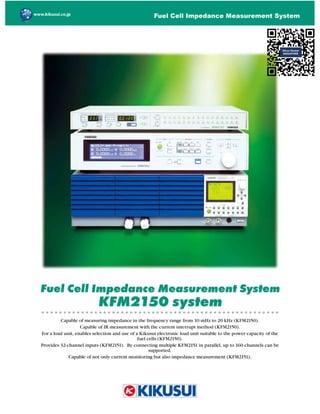
The fuel cell impedance measurement system is con gured with an fuel cell impedance meter KFM2150
and a Kikusui PLZ-4W series electronic load unit. Thus, the impedance measurement system can be
con gured to meet the output capacity of the fuel cells. Also, the system can support single fuel cells
when configured with an electronic load unit supporting 0-V input. The system is capable of both
impedance measurement with the AC impedance method and IR measurement with the current interrupt
method, and is capable of acquiring the following types of data using the supplied application software:
I-V characteristics and constant current characteristics; Cole-Cole plot data with the AC impedance
method; and data with the current interrupt method. Also, the system provides a sequence function to
execute tests for acquiring these types of data in the order they are speci ed.
)HDW UHV
■ DSDEOH RI PHDV UL LPSHGD FH L WKH IUHT H F UD H IURP P ]
WR ]
■ 2SHUDWL YROWD HV WR WR
■ ( DEOHV VHOHFWLR RI F UUH W D G SRZHU FDSDFLWLHV E RSHUDWL
P OWLSOH LWV RI WKH VDPH PRGHO RI WKH 3/ : VHULHV L SDUDOOHO
■ ( DEOHV VHWWL RI D PHDV UHPH W F UUH W L WKH UD H RI WR
L VWHSV RI WKH ORDG F UUH W
■ ( DEOHV FKD L RI WKH ORDG F UUH W ZKLOH PDL WDL L WKH VHWWL
RI WKH PHDV UHPH W F UUH W
■ DSDEOH RI ,5 PHDV UHPH W ZLWK WKH F UUH W L WHUU SW PHWKRG
■ /RZ YROWD H SURWHFWLR HT LSSHG DV VWD GDUG
■ ([WHU DO L WHUIDFH HT LSSHG DV VWD GDUG 56 *3,% D G 6%
The fuel cell impedance meter KFM2150 cannot
be used alone.
It needs to be combined with a Kikusui PLZ-4W
series electronic load unit, and be calibrated.
KFM2150 SYSTEM 1000-01
bench top type
Upper unit: KFM2150
Lower unit: PLZ1004W
KFM2150 SYSTEM
) HO FHOO LPSHGD FH PHDV UHPH W V VWHP
* Value assumed when combined with a 0-V input type.](data:image/gif;base64,R0lGODlhAQABAIAAAAAAAP///yH5BAEAAAAALAAAAAABAAEAAAIBRAA7)
More Related Content
What's hot
What's hot (20)
Similar to Kikusui fuel cell_meter_kfm2150_print
Similar to Kikusui fuel cell_meter_kfm2150_print (20)
More from NIHON DENKEI SINGAPORE
More from NIHON DENKEI SINGAPORE (20)
Recently uploaded
Recently uploaded (20)
Kikusui fuel cell_meter_kfm2150_print
- 2. SS S S The fuel cell impedance measurement system is con gured with an fuel cell impedance meter KFM2150 and a Kikusui PLZ-4W series electronic load unit. Thus, the impedance measurement system can be con gured to meet the output capacity of the fuel cells. Also, the system can support single fuel cells when configured with an electronic load unit supporting 0-V input. The system is capable of both impedance measurement with the AC impedance method and IR measurement with the current interrupt method, and is capable of acquiring the following types of data using the supplied application software: I-V characteristics and constant current characteristics; Cole-Cole plot data with the AC impedance method; and data with the current interrupt method. Also, the system provides a sequence function to execute tests for acquiring these types of data in the order they are speci ed. )HDW UHV ■ DSDEOH RI PHDV UL LPSHGD FH L WKH IUHT H F UD H IURP P ] WR ] ■ 2SHUDWL YROWD HV WR WR ■ ( DEOHV VHOHFWLR RI F UUH W D G SRZHU FDSDFLWLHV E RSHUDWL P OWLSOH LWV RI WKH VDPH PRGHO RI WKH 3/ : VHULHV L SDUDOOHO ■ ( DEOHV VHWWL RI D PHDV UHPH W F UUH W L WKH UD H RI WR L VWHSV RI WKH ORDG F UUH W ■ ( DEOHV FKD L RI WKH ORDG F UUH W ZKLOH PDL WDL L WKH VHWWL RI WKH PHDV UHPH W F UUH W ■ DSDEOH RI ,5 PHDV UHPH W ZLWK WKH F UUH W L WHUU SW PHWKRG ■ /RZ YROWD H SURWHFWLR HT LSSHG DV VWD GDUG ■ ([WHU DO L WHUIDFH HT LSSHG DV VWD GDUG 56 *3,% D G 6% The fuel cell impedance meter KFM2150 cannot be used alone. It needs to be combined with a Kikusui PLZ-4W series electronic load unit, and be calibrated. KFM2150 SYSTEM 1000-01 bench top type Upper unit: KFM2150 Lower unit: PLZ1004W KFM2150 SYSTEM ) HO FHOO LPSHGD FH PHDV UHPH W V VWHP * Value assumed when combined with a 0-V input type.
- 3. ● 6 VWHP VWU FW UH H[DPSOHV System lineup and main speci cations KFM2150 SYSTEM 9000-05 PLZ2004WB (4 units) 5DF PR W W SH [Accessories] Instruction manual × 1, power cord × 1, sensing wires × 1 set, at cable × 1 set, application software (CD) × 1, RS232C cable × 1 set, 1 set of two parallel load cables (for the KFM2150 SYSTEM 1320-02A and the KFM2150 SYSTEM 3000-02 only) %H FK WRS W SH KFM2150 SYSTEM 1000-01 LPH VLR V ZHL KWV ●%H FK WRS W SH R O ZHL KWV PH WLR HG KFM2150 SYSTEM 165-01A: Approx. 13.5kg KFM2150 SYSTEM 660-01A: Approx. 22kg KFM2150 SYSTEM 1320-02A: Approx. 38kg KFM2150 SYSTEM 1000-01: Approx. 21kg KFM2150 SYSTEM 3000-02: Approx. 45kg ●5DF PR W W SH KFM2150 SYSTEM 1980-03A: 570W × 1430H × 875D mm/Approx. 170kg KFM2150 SYSTEM 2640-04A: 570W × 1430H × 875D mm/Approx. 185kg KFM2150 SYSTEM 3300-05A: 570W × 1430H × 875D mm/Approx. 200kg KFM2150 SYSTEM 5000-03: 570W × 1430H × 1025D mm/Approx. 190kg KFM2150 SYSTEM 7000-04: 570W × 1430H × 1025D mm/Approx. 215kg KFM2150 SYSTEM 9000-05: 570W × 1430H × 1025D mm/Approx. 240kg PLZ1004W KFM2150 * The blank panel may be different from that shown in the photo. *1: H and M ranges: ±(0.3 % of rdng + 0.3 % of f.s), f.s: full scale of the H range L range: ±(0.3 % of rdng + 0.3 % of f.s), f.s: full scale of the L range *2: All ranges: ±(0.1 % of rdng + 0.1 % of rng) [Note] rdng: Stands for reading. rng: Stands for range value. f.s: Stands for full scale. Speci cations Units con guring the system Rating Model Impedance meter Electronic load unit Operation modes: constant current (CC) + constant voltage (CV) Structure Operating voltage Current Power V A W KFM2150 SYSTEM 165-01A KFM2150 PLZ164WA (1 unit) Bench top type 0 to 150 165 KFM2150 SYSTEM 660-01A KFM2150 PLZ664WA (1 unit) Bench top type 0 to 150 132 660 KFM2150 SYSTEM 1320-02A KFM2150 PLZ664WA (2 units) Bench top type 0 to 150 264 1320 KFM2150 SYSTEM 1980-03A KFM2150 PLZ664WA (3 units) Rack mount type 0 to 150 396 1980 KFM2150 SYSTEM 2640-04A KFM2150 PLZ664WA (4 units) Rack mount type 0 to 150 528 2640 KFM2150 SYSTEM 3300-05A KFM2150 PLZ664WA (5 units) Rack mount type 0 to 150 660 3300 KFM2150 SYSTEM 1000-01 KFM2150 PLZ1004W (1 unit) Bench top type 1.5 to 150 200 1000 KFM2150 SYSTEM 3000-02 KFM2150 PLZ1004W (1 unit) + PLZ2004WB (1 unit) Bench top type 1.5 to 150 600 3000 KFM2150 SYSTEM 5000-03 KFM2150 PLZ1004W (1 unit) + PLZ2004WB (2 units) Rack mount type 1.5 to 150 1000 5000 KFM2150 SYSTEM 7000-04 KFM2150 PLZ1004W (1 unit) + PLZ2004WB (3 units) Rack mount type 1.5 to 150 1400 7000 KFM2150 SYSTEM 9000-05 KFM2150 PLZ1004W (1 unit) + PLZ2004WB (4 units) Rack mount type 1.5 to 150 1800 9000 Speci cations Constant current mode (CC) Ammeter display Constant voltage mode (CV) Voltmeter display Model Allowable ranges (A)/Resolution (mA) Accuracy *1 Allowable ranges (V)/ Resolution (mV) Accuracy H range M range L range H range (A) M range (A) L range (A) 15-V range 150-V range 10-V range (V) 100-V range (V) 150-V range (V) KFM2150 SYSTEM 165-01A 0 to 33/1 0 to 3.3/0.1 0 to 0.33/0.01 0.0000 to 33.000 0.0000 to 3.3000 0.0000 to 0.3300 0 to 15.75/1 0 to 157.5/10 0.0000 to 9.9999 10.000 to 99.999 100.00 to 150.00 KFM2150 SYSTEM 660-01A 0 to 132/10 0 to 13.2/1 0 to 1.32/0.1 0.0000 to 132.00 0.0000 to 13.200 0.0000 to 1.3200 KFM2150 SYSTEM 1320-02A 0 to 264/20 0 to 26.4/2 0 to 2.64/0.2 0.0000 to 264.00 0.0000 to 26.400 0.0000 to 2.6400 KFM2150 SYSTEM 1980-03A 0 to 396/30 0 to 39.6/3 0 to 3.96/0.3 0.0000 to 396.00 0.0000 to 39.600 0.0000 to 3.9600 KFM2150 SYSTEM 2640-04A 0 to 528/40 0 to 52.8/4 0 to 5.28/0.4 0.0000 to 528.00 0.0000 to 52.800 0.0000 to 5.2800 KFM2150 SYSTEM 3300-05A 0 to 660/50 0 to 66/5 0 to 6.6/0.5 0.0000 to 660.00 0.0000 to 66.000 0.0000 to 6.6000 KFM2150 SYSTEM 1000-01 0 to 200/10 0 to 20.0/1 0 to 2.00/0.1 0.0000 to 200.00 0.0000 to 20.000 0.0000 to 2.0000 0 to 15.75/1 0 to 157.5/10 0.0000 to 9.9999 10.000 to 99.999 100.00 to 150.00 KFM2150 SYSTEM 3000-02 0 to 600/30 0 to 60.0/3 0 to 6.00/0.3 0.0000 to 600.00 0.0000 to 60.000 0.0000 to 6.0000 KFM2150 SYSTEM 5000-03 0 to 1000/50 0 to 100.0/5 0 to 10.00/0.5 0.0000 to 1000.0 0.0000 to 100.00 0.0000 to 10.000 KFM2150 SYSTEM 7000-04 0 to 1400/70 0 to 140.0/7 0 to 14.00/0.7 0.0000 to 1400.0 0.0000 to 140.00 0.0000 to 14.000 KFM2150 SYSTEM 9000-05 0 to 1800/90 0 to 180.0/9 0 to 18.00/0.9 0.0000 to 1800.0 0.0000 to 180.00 0.0000 to 18.000
- 4. 4 ) HVWHU V SSOLHG DSSOLFDWLR VRIWZDUH Current [A] Time [S] Step current Step time Fold-back current Final current Rest time Start current ▲ I-V measurement ▲ I-V + AC impedance measurement ▲ I-V + Cole-Cole plot measurement Current [A] Step time Start current Step time AC impedance measurement frequency (fixed at one point) Time [S] Rest time Measure rest time Final current Fold-back current Current [A] Step time Start current AC impedance measurement start-to-stop frequencies Time [S] Rest time Measure rest time Final current Fold-back current Step current ▲ Cole-Cole plot measurement ▲ AC impedance measurement ▲ Current interrupt measurement ▲ Constant current test Start frequency-to-stop frequency Rest time Current [A] Time [s] Current Rest time Current [A] Time [s] Current Generating time Halt time Current [A] Time [s] Current Generating time Current [A] Time [s] Rest time Voltage [V] Sampling position Sampling region Repeat count 2nd time nth time Pulse Depth 1st time (fixed to 100 ms) Transition time Pulse width Transition time Display data Trigger point Current "FC Tester" enables control of the KFM system from a PC, conducting tests for acquiring the characteristics of fuel cells, such as I-V characteristics, constant current characteristics, and Cole-Cole plot and other data with the current interrupt method and the AC impedance method. It also enables tests to be conducted in the order they are speci ed. When combined with the fuel cell scanner KFM2151, it can support easurement of the impedance of each cell while switching from one cell to another in sequence. )HDW UHV ■ 3URYLGHV VWDUW S D G VK WGRZ VHT H FHV IULH GO WR I HO FHOOV ■ 3URYLGHV WHVW PRGHV IRU , FKDUDFWHULVWLFV FR VWD W F UUH W FKDUDFWHULVWLFV D G ROH ROH SORW GDWD ZLWK WKH LPSHGD FH PHWKRG ■ ( DEOHV I HO FHOO F FOH WHVWV E FRPEL L VHT H FH I FWLR V ■ 3URYLGHV UHDO WLPH UDSK I FWLR V ■ Enables output of test results data as CSV les (text format). ■ ( DEOHV REVHUYDWLR RI YROWD H D G F UUH W ZDYHIRUPV G UL WKH F UUH W L WHUU SW PHWKRG ■ 3URYLGHV SD HO FR WURO I FWLR V WKDW H DEOH D 3 WR EH VHG WR SHUIRUP RSHUDWLR V HT LYDOH W WR .)0 SD HO RSHUDWLR V ■ ( DEOHV PHDV UHPH W RI WKH LPSHGD FH RI HDFK FHOO ZKH FRPEL HG ZLWK WKH ) VFD HU .)0 ■ "FC Tester" consists of three programs, Con guration Tool, Condition Editor, and Executive. ● Con guration Tool This program con gures the fuel cell impedance measurement system. It is used to con gure the system for the rst time or to change the system con guration. ● R GLWLR (GLWRU This program creates and edits test conditions. It enables setting of test mode conditions on 15 sheets in total, one sheet for one test mode. It also enables setting of the repeat count of each sheet and the repeat count (cycle) for all sheets. ▲ Cycle window ▲ Sequence window R FHSW DO GLD UDPV RI WHVW PRGH RSHUDWLR
- 5. 5 ● ([HF WLYH This program executes characteristic tests in accordance with the test condition le created with Condition Editor. It monitors each measurement at the start and stop of a test and during the test. It can graphically represent voltage, current, and impedance trends in real time. ▲ Cole-Cole plot window (3D graphic display) ▲ I-V characteristics window FC KFM2151 To each cell 5HFRPPH GHG RSHUDWL H YLUR PH W The following are the hardware and software requirements for using the supplied application software. ● IBM-PC/AT or compatible, with a 600-MHz Pentium III microprocessor or equivalent or higher (Pentium 4 or equivalent or higher recommended) ● Microsoft Windows 2000 (Windows 2000 SP4 or later required), Microsoft Windows XP (Windows XP SP2 or later required) ● 256 MB memory or greater (512 MB or greater recommended). When using FC scanner (KFM2151), 512 MB or greater (1 GB or greater recommended) ● SVGA resolution or higher (800 x 600 dots or greater) ● 20 MB free hard disk space or greater (another free space required for data storage) ● CD-ROM drive ● Mouse or other pointing device ● Interface (RS232C, GPIB, or USB) ● GPIB board (only if used with GPIB) manufactured by one of National Instruments, Agilent, Contec Co., Ltd., and Interface Corporation. ● VISA VISA library One of NI-VISA 3.0 or later, Agilent I/O Library M01.00 or later, and KI-VISA 2.5 or later * The Virtual Instrument Software Architecture (VISA) is a standard speci cation for software for connecting measuring instruments that was established by VXI plug&play Systems Alliance. * KI-VISA is an Kikusui Electronics Corporation's original I/O library conforming to the VXI plug&play VISA speci cation 3.0. * The latest KI-VISA is downloadable at our web site. .)0 ) HO HOO 6FD HU The Fuel cell scanner KFM2151 is a 32-channel scanner that meets the essential request to monitor each cell in the evaluation of stack fuel cells. To support stacks of various sizes, it is possible to support up to 160 channels by connecting multiple KFM2151 in parallel. As a mean to eliminate the cumbersome work of wiring, the KFM2151 provides a function whereby once it is connected to cells, the terminals allocated to channels can be changed so that the voltage and impedance of any cell can be measured without rewiring. For a voltage monitor function, it offers a scan speed of 32 channels per second, which is suf cient from the practical viewpoint. ● LPH VLR V PD[LP P :HL KW 430 (435) W × 44 (60) H × 270 (285) D mm/about 3.5 kg )HDW UHV ■ DSDEOH RI LPSHGD FH PHDV UHPH W DW D L S W YROWD H S WR ZKH FR HFWHG WR WKH .)0 ZLWK D GHGLFDWHG FDEOH ■ 2 H LW V SSRUWV FKD HO L S WV D G S WR FKD HOV FD EH V SSRUWHG E FR HFWL P OWLSOH LWV L SDUDOOHO ■ :LWK LWV FKD HO DOORFDWHG WHUPL DO FKD L I FWLR H DEOHV PHDV UHPH W RI WKH YROWD H D G LPSHGD FH RI D FHOO R FH LW LV FR HFWHG WR FHOOV ■ ( DEOHV VHWWL RI 2 3 D G 3 IRU HDFK FKD HO ■ DSDEOH RI PR LWRUL YROWD H DW D VFD VSHHG RI FKD HOV SHU VHFR G ■ D EH RSHUDWHG DOR H DV D YROWD H PR LWRU FKD HO YROWD H VFD HU WKDW V SSRUWV VWDF I HO FHOOV DSDEOH RI LPSHGD FH PHDV UHPH W ZKH FRPEL HG ZLWK WKH .)0
- 6. 6 KFM2150 speci cations ■ Common speci cations ● Impedance measurement section (AC impedance method) Frequency range....................10 mHz to 20 kHz Frequency resolution .............14 points of 1.00, 1.26, 1.58, 2.00, 2.51, 3.00, 3.16, 4.00, 5.00, 6.00, 6.30, 7.00, 8.00, and 9.00/decade (decimal 7-digit range) Measurement range...............0.0001 mΩ to 9.9999 Ω, indicated in ve digits. Measurement AC current.......0.1 to 10 % of DC load current (settable in 0.1 % steps). Note that the sum of the DC load current and the measurement AC current must not exceed the rating of the PLZ-4W series unit. The actual allowable current range varies depending on which PLZ-4W unit the KFM2150 is combined with. By setting the measurement AC current to 0%, it is possible to set the measurement AC current to OFF. The maximum measurement AC current is 80 Arms, 50 Arms* * Value assumed when the KFM2150 is combined with a 0 V input type. Measurement items ...............R, X, |z|, θ Measurement accuracy (example of SYSTEM1000-01, 10 V range) (Current interrupt method) Measurement range...............0.0001 mΩ to 9.9999 Ω, indicated in ve digits. Measurement items ...............IR (internal resistance) Interrupt pulse parameters Pulse depth PD ......................0 to 100 % of DC load current (settable in 1 % steps). Can be measured with consideration given to the effect on the fuel cells. Pulse width PW......................0.1 ms to 10 ms (settable in 0.1 ms steps). Can be measured with consideration given to the effect on the fuel cells and the DC load current. Pulse change time PT............0.01 ms* to 10 ms (settable in 0.01 ms steps). Can be measured with consideration given to the effect of the load wiring inductance. *The minimum is restricted by the slew rate of the PLZ-4W series unit used and the PD setting. ● Average setting ......................Moving average, 1 to 256 times ● Protection function Low voltage protection (UVP)...Turns the load off at –2 V to 150 V (settable). Output an alarm signal. Load protection ......................Turns the load off upon receiving an alarm signal from the PLZ-4W series unit. Output an alarm. ● External control Interface .................................RS232C, GPIB, USB ● General speci cations Input voltage range ................100 VAC to 240 V (90 VAC to 250 V), single phase Input frequency range............47 Hz to 63 Hz Power consumption ...............100 VA max. DC load current KFM2151 speci cations ● Inputs Number of inputs................. O Rated input .......................... ±150 V (±200 V max.) ● 2 O Number of outputs............... 1 channel. channel during setting or scanning is 1/10 before being output.) ● Voltage measurement section Number of channels............ 32 ch. An input terminal can be set for each channel. (Up to 160 channels can be supported by connecting multiple KFM2151 in parallel.) Ranges ................................ Auto ranges of 2 V, 20 V, and 200 V Scan speed ......................... O OVP ..................................... –2 V to 200 V. Can be set for each channel. Setting resolution: 0.01 V UVP ..................................... –2 V to 200 V. Can be set for each channel. Setting resolution: 0.01 V Voltmeter.............................. Display of 19999, accuracy: ±(0.1 % of rdng + 0.1 % of rng) rdng: reading, rng: range value ● Impedance measurement channel switching section Number of channels............ 32 ch. An input terminal can be set for each channel. (Up to 160 channels can be supported by connecting multiple KFM2151 in parallel.) Switching............................. Auto scan, manual selection Voltage at which impedance measurement is possible ............................................. Up to 150 V (when connected to the KFM2150). To remove the effect of the impedance meter on measurement accuracy (when connected to the KFM2150), Frequencies up to 3 kHz ..... Add 2 % 3.16 kHz to 9 kHz ................ Add 3 % 10 kHz to 20 kHz ................. Add 5 % to the |Z| percentage reading. Note: For the 10 mΩ range only, add 3 mΩ to ±(|Z| percentage reading). ● Communication, IF RS232C interface for PC connection I/O interface for impedance meter connection Interface for parallel connection ● General speci cations Input voltage range ............. 100 VAC to 240 V (90 VAC to 250 V), single phase Input frequency range......... 47 Hz to 63 Hz Power consumption............. 30 VA max. Insulation resistance........... 30 MΩ or greater (500 VDC) between AC line Withstand voltage ............... Free from defects when 1500 VAC is applied for 1 min. between AC line and chassis.
- 7. 7 ▲Cable with coating ▲Cable with its coating removed *Note: In actual measurement, be sure to use it with its coating intact. (IIHFW RI WKH ORDG FDEOH R PHDV UHPH W In the measurement of the impedance of fuel cells, an important point is the load cable to use. In particular, if fuel cells with large current capacities are to be measured, measurement results are affected by the material, thickness, length, and other factors of the load cable. Bear this in mind before measurement. <Points to consider> ● Use a suf ciently thick cable to measure fuel cells with large current capacities. If a thin load cable is used, this will cause a large voltage drop, generating heat due to power loss, which is very dangerous. If the voltage drop is large, the voltage may drop below the operating voltage of the electronic load unit, making it impossible to ow current. ● VH D WKLF D G VKRUW R H IRU LPSHGD FH PHDV UHPH W In AC impedance measurement, the larger the measurement AC current and the higher the measurement frequency, the thicker and shorter the load cable must be used. <Reference> The photos show a load cable (example) that Kikusui use to test rack amount type systems with load currents of about 1000 A. Kikusui accept orders to manufacture load cables (custom made cables). Feel free to consult us when asking for an estimate of your system. System speci cations The speci cations are speci ed by following setting and conditions, unless otherwise stated: ● Warmup time: 30 min. (state with current being owed) ● Temperature: 20 °C to 30 °C ● Relative humidity: 20 %rh to 85 %rh ■ Accuracy of impedance measurement with the AC impedance method (2-meter load cable used) If the current range on the load unit is H or M, and the measurement AC current is 0.5 Arms or greater. ± (% of the |z| reading) Frequency to 126 Hz 158 Hz to 3 kHz 3.16 k to 9 kHz 10 k to 20 kHz Accuracy R, X (of reading) 10 mΩ range 3 % 2 % 3 % 4 % 100 mΩ range 3 % 2 % 3 % 5 % 1000 mΩ range 4 % 3 % 6 % 10 Ω range 4 % 8 %(to 1 kHz) ● When the sensing end input voltage is 0 V to 10 V (10 V range) *This catalog contains the speci cations of KFM2150 SYSTEM 1000-01 (KFM2150 + PLZ1004W) as a typical example. For the speci cations of other systems, contact Kikusui. For the 10 mΩ range only, add 0.3 mΩ to ± (% of |z| reading). The hatched portion is not speci ed ± (% of the |z| reading) Frequency to 126 Hz 158 Hz to 3 kHz 3.16 k to 9 kHz 10 k to 20 kHz Accuracy R, X (of reading) 10 mΩ range 5 % 3 % 5 % 6 % 100 mΩ range 5 % 3 % 5 % 8 % 1000 mΩ range 6 % 5 % 8 % 10 Ω range 6 % 9 %(to 1 kHz) ● When the sensing end input voltage is 10 V to 100 V (100 V range) For the 10 mΩ range only, add 0.3 mΩ to ±(% of |z| reading). The hatched portion is not speci ed. ± (% of the |z| reading) Frequency to 126 Hz 158 Hz to 3 kHz 3.16 k to 9 kHz 10 k to 20 kHz Accuracy R, X (of reading) 10 mΩ range 100 mΩ range 9 % 6 % 9 % 1000 mΩ range 12 % 9 % 10 Ω range 12 % ● When the sensing end input voltage is 100 V to 150 V (100 V range) The hatched portion is not speci ed ■ Accuracy of IR measurement with the current interrupt method.................±3 % If, however, measurement is conducted under the conditions below, with 10 mΩ resistance connected to the power supply in series. ● Input terminal voltage............................... 5 V ● Load current.............................................. 20 A ● Pulse depth............................................... 50 % (10 A) ● Pulse width ............................................... 10 ms ● Pulse change time.................................... 10 ms ● Sampling position..................................... 5 ms ● Sampling region........................................ 0.51 ms ● Average..................................................... ■ General speci cations Input voltage range....................................... 90 VAC to 250 V, 47 Hz to 63 Hz, single phase Power consumption...................................... 260 VA max. Installation altitude ....................................... 2000 meters or less Speci cations-assured temperature range... 20 °C to 30 °C Speci cations-assured humidity range......... 20 %rh to 85 %rh (no condensation) Operating temperature range....................... 0 °C to 40 °C Operating humidity range............................. 20 %rh to 85 %rh (no condensation) Weight........................................................... Approx. 21 kg Load cable example (1000 A class) • Mounting hole diameter: 14 mm • Mounting pitch: 40 mm • Nominal cross sectional area: 600 mm • Length: about 2 meters • Weight: Approx. 13 kg
- 8. 3 D D 1 3 D ■ All products contained in this catalogue are equipment and devices that are premised on use under the supervision of quali ed personnel, and are not designed or produced for home-use or use by general consumers. ■ Speci cations, design and so forth are subject to change without prior notice to improve the quality. ■ Product names and prices are subject to change and production may be discontinued when necessary. ■ Product names, company names and brand names contained in this catalogue represent the respective registered trade name or trade mark. ■ Colors, textures and so forth of photographs shown in this catalogue may differ from actual products due to a limited delity in printing. ■ Although every effort has been made to provide the information as accurate as possible for this catalogue, certain details have unavoidably been omitted due to limitations in space. ■ If you nd any misprints or errors in this catalogue, it would be appreciated if you would inform us. ■Please contact our distributors to con rm speci cations, price, accessories or anything that may be unclear when placing an order or concluding a purchasing agreement. ●Distributor: www.kikusui.cn Room 305,Shenggao Building , No.137,Xianxia Road, Shanghai City,China Phone : 021-5887-9067 Facsimile : 021-5887-9069 www.kikusuiamerica.com 1-310-214-0000 3625 Del Amo Blvd, Suite 160, Torrance, CA 90503 Phone : 310-214-0000 Facsimile : 310-214-0014 Southwood 4F,6-1 Chigasaki-chuo,Tsuzuki-ku,Yokohama,224-0032,Japan Phone: (+81)45-482-6353,Facsimile: (+81)45-482-6261,www.kikusui.co.jp LPH VLR DO R WOL H GUDZL V * For outside dimensions of the PLZ-4W series units, refer to their respective catalogs. MAX455 (17.91) 430 (16.93) MAX10 (0.39) MAX20 (0.79) 270 (10.63) MAX330 (12.99) 88 (3.46) MAX105 (4.13) 430 (16.93) MAX435 (17.13) 270 (10.63) MAX5 (0.20) MAX285 (11.22) 44 (1.73) MAX60 (2.36) 100 (3.94) 1200 (47.24) 570 (22.44) (80(3.15)) 1350 (53.15) 50 (1.97) 650 (25.59) 800 (31.50) MAX75 (2.95) (780(30.71)) 800 (31.50) 950 (37.40) MAX75 (2.95) (780(30.71)) ▲If using the PLZ2004WB (booster) Systems to which these drawings apply ●KFM SYSTEM5000-03 ●KFM SYSTEM7000-04 ●KFM SYSTEM9000-05 ▲If not using the PLZ2004WB (booster) Systems to which these drawings apply ●KFM SYSTEM1980-03A ●KFM SYSTEM2640-04A ●KFM SYSTEM3300-05A ●.)0 ●.)0 ●.)0 6 6 (0 GHSWK YDULHV GHSH GL R WKH V VWHP Unit: mm (inch)