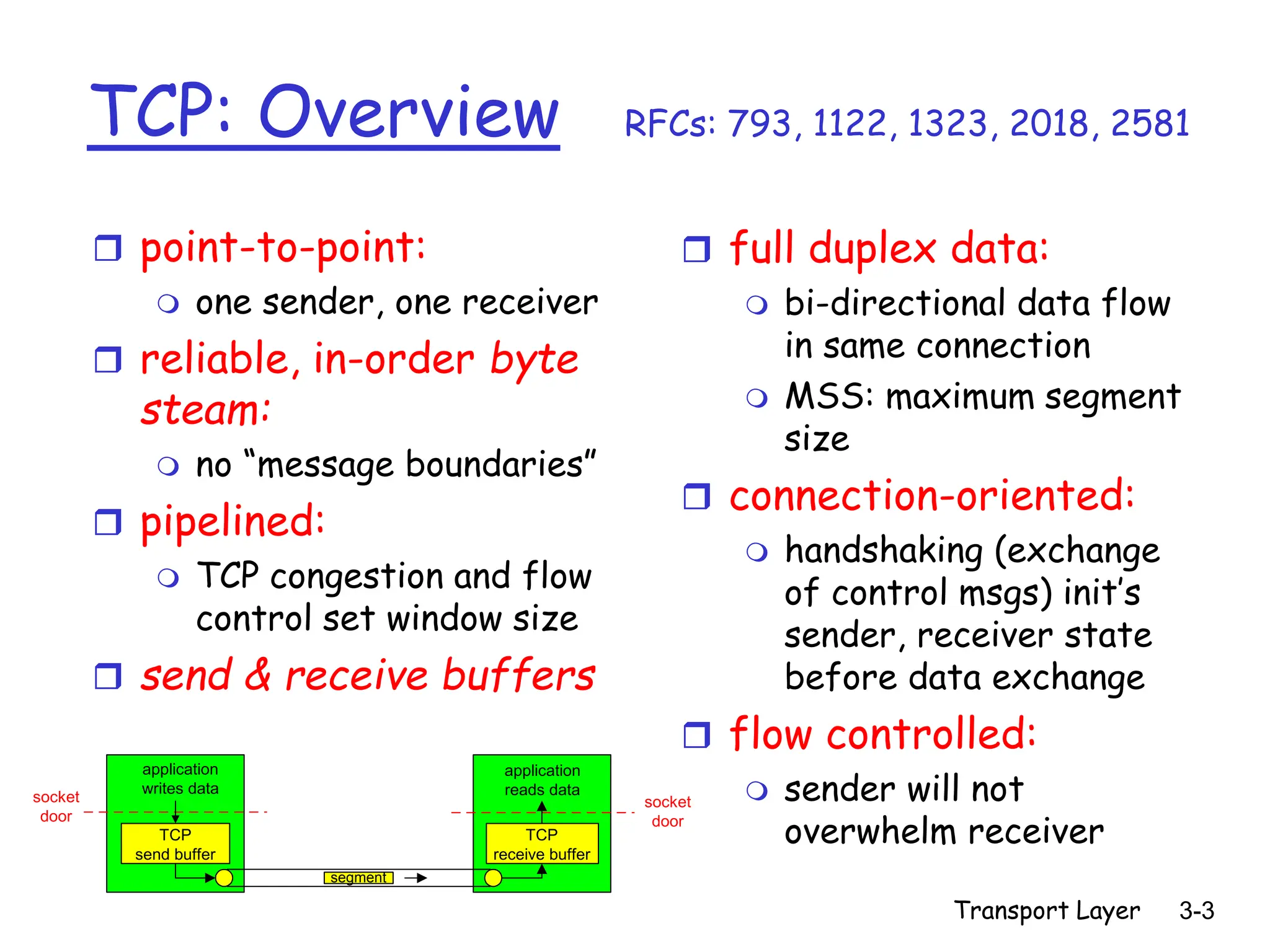
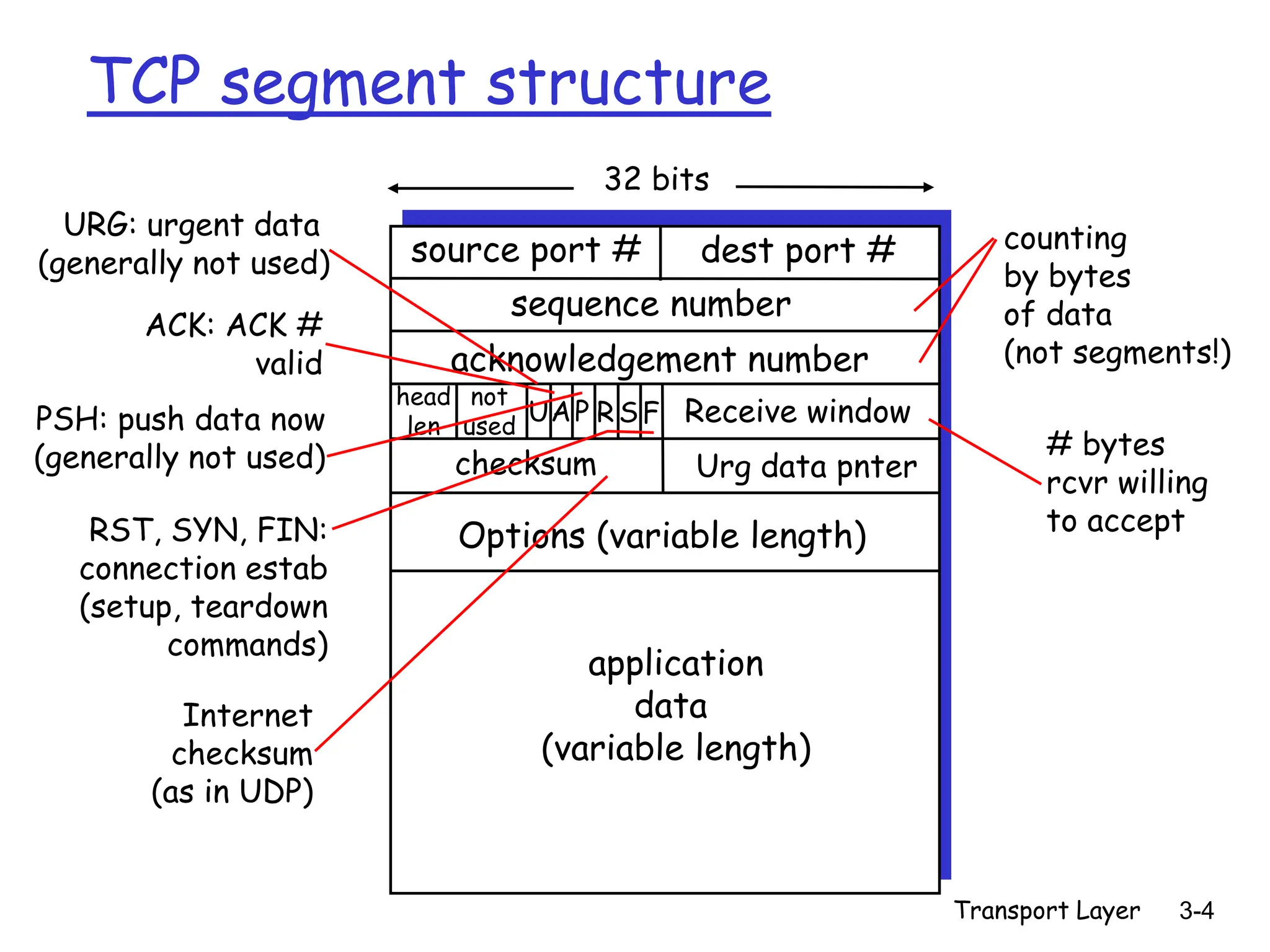
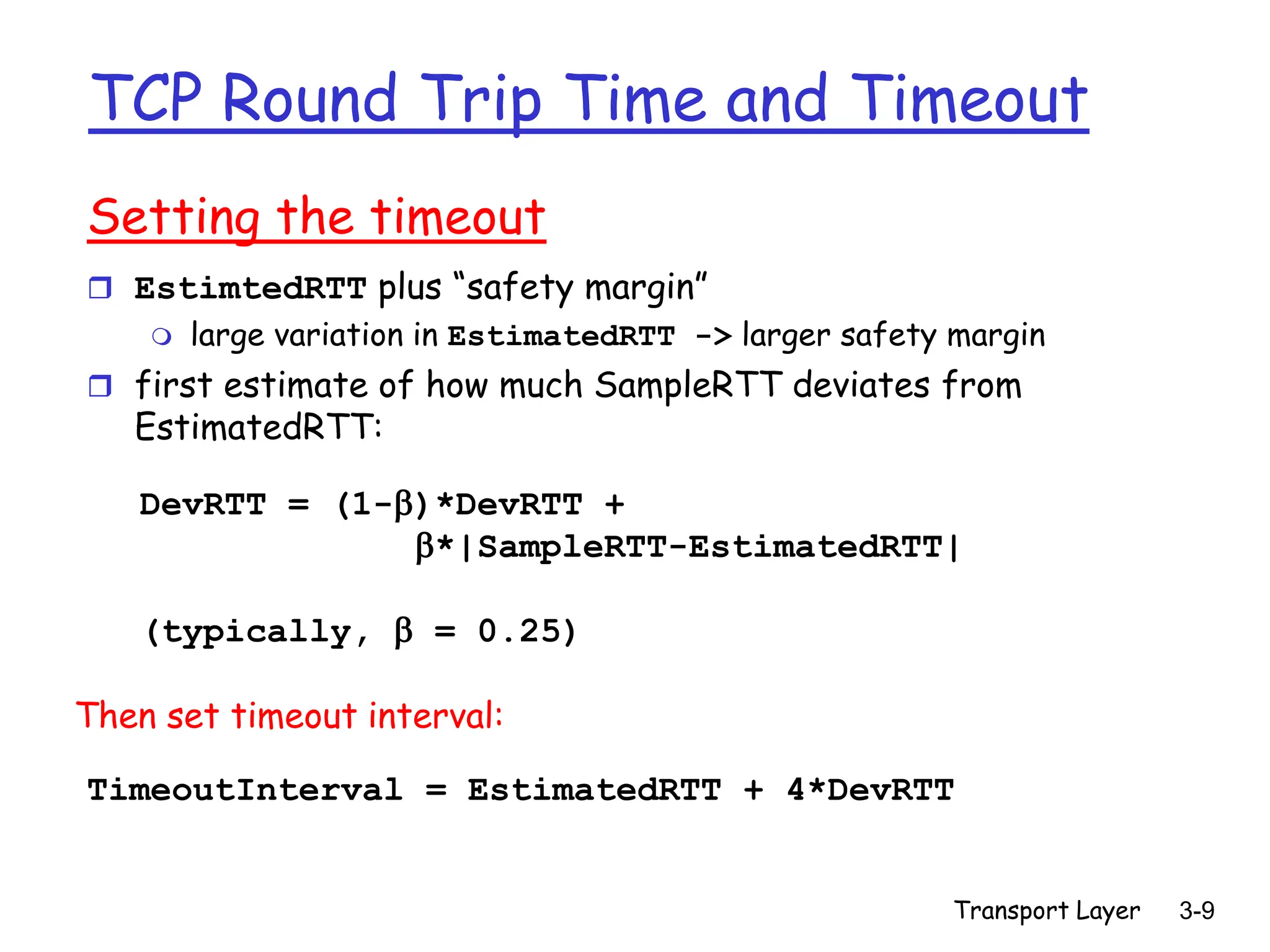
This document provides an overview of key concepts in TCP (Transmission Control Protocol) including:
- TCP segment structure with fields like sequence numbers, acknowledgement numbers, and windows.
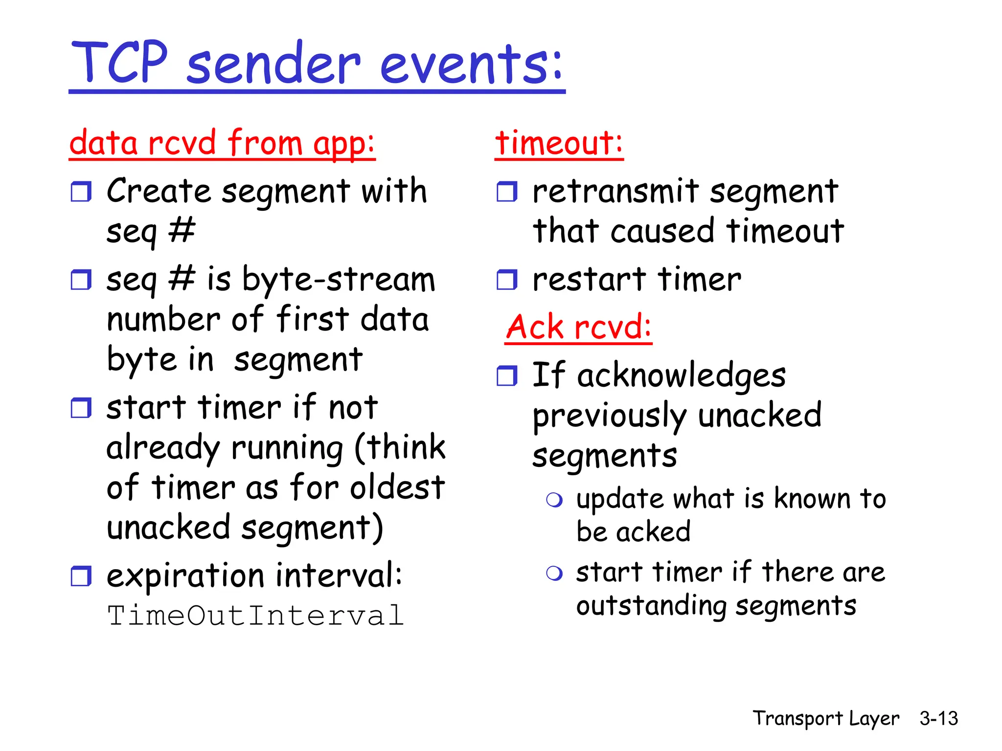
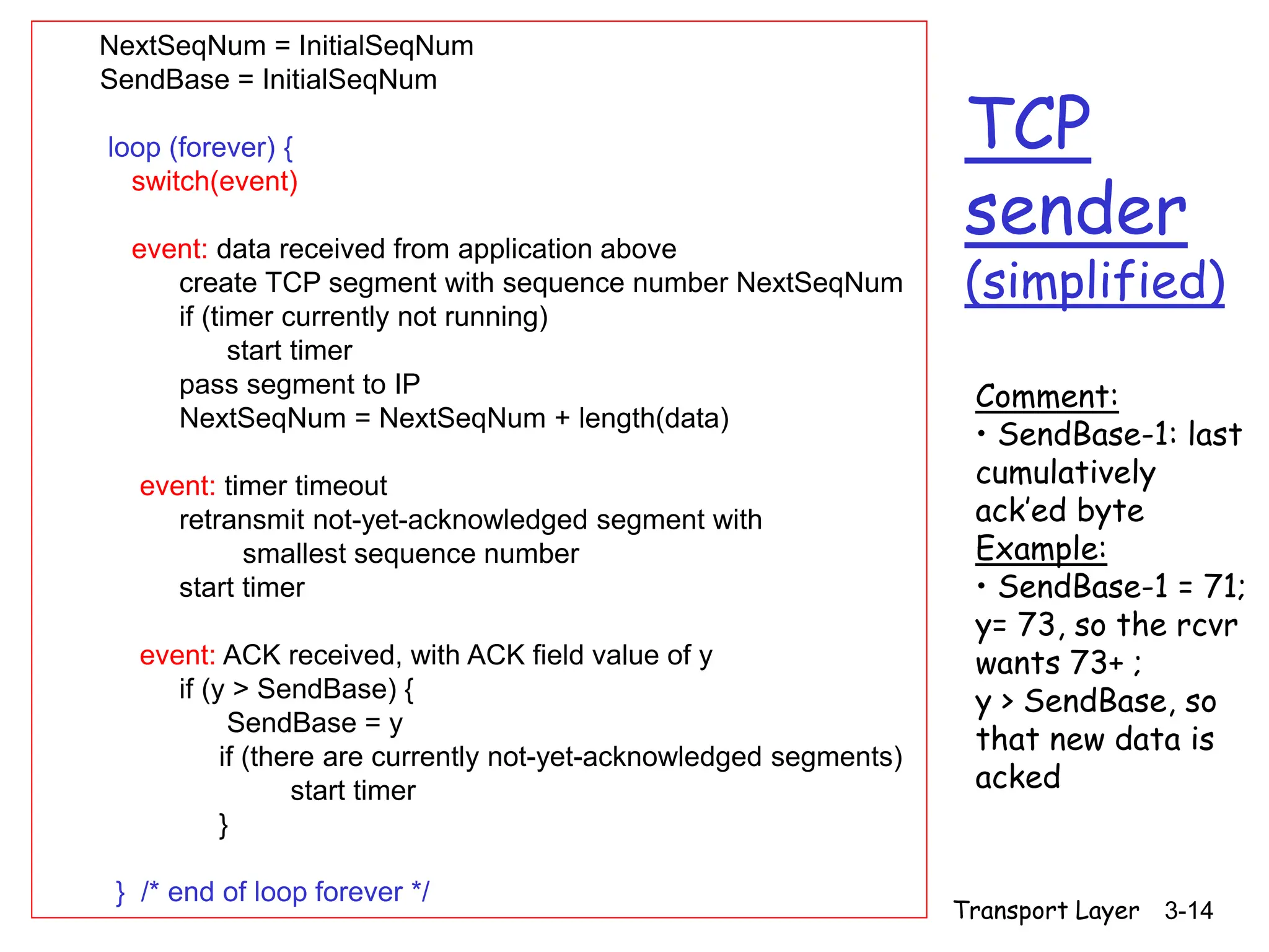
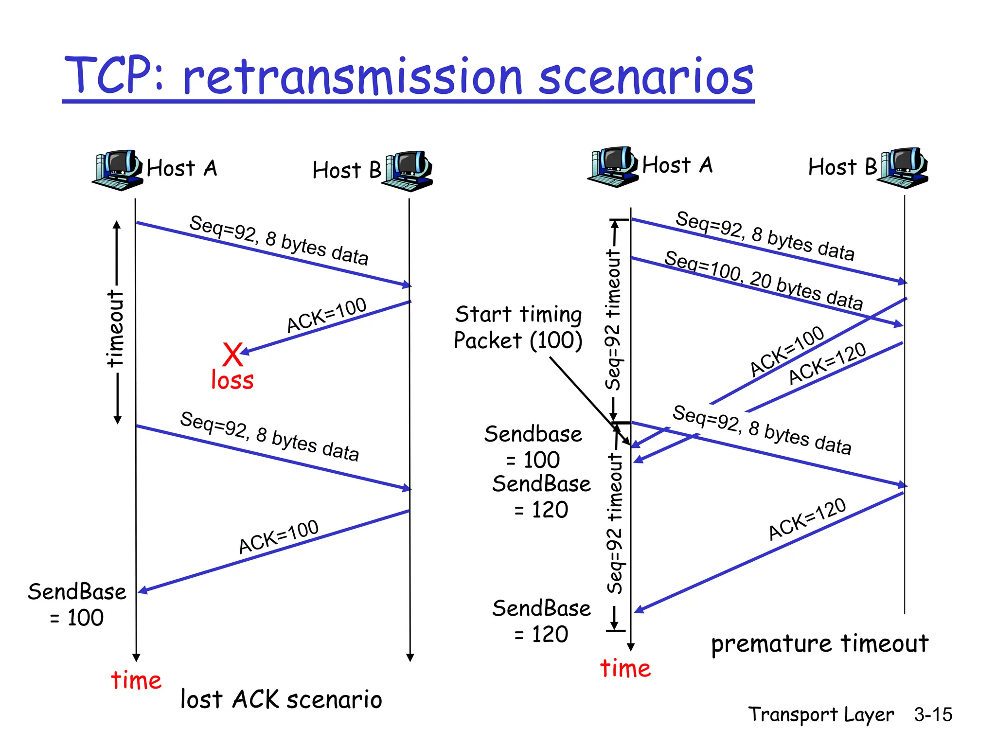
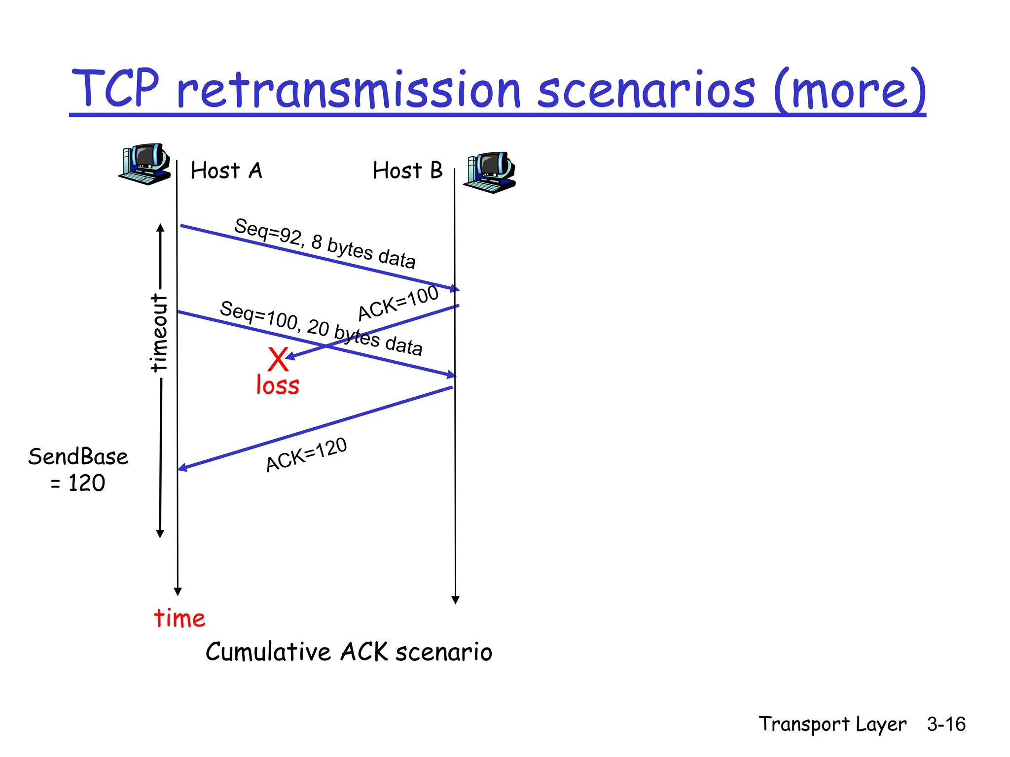
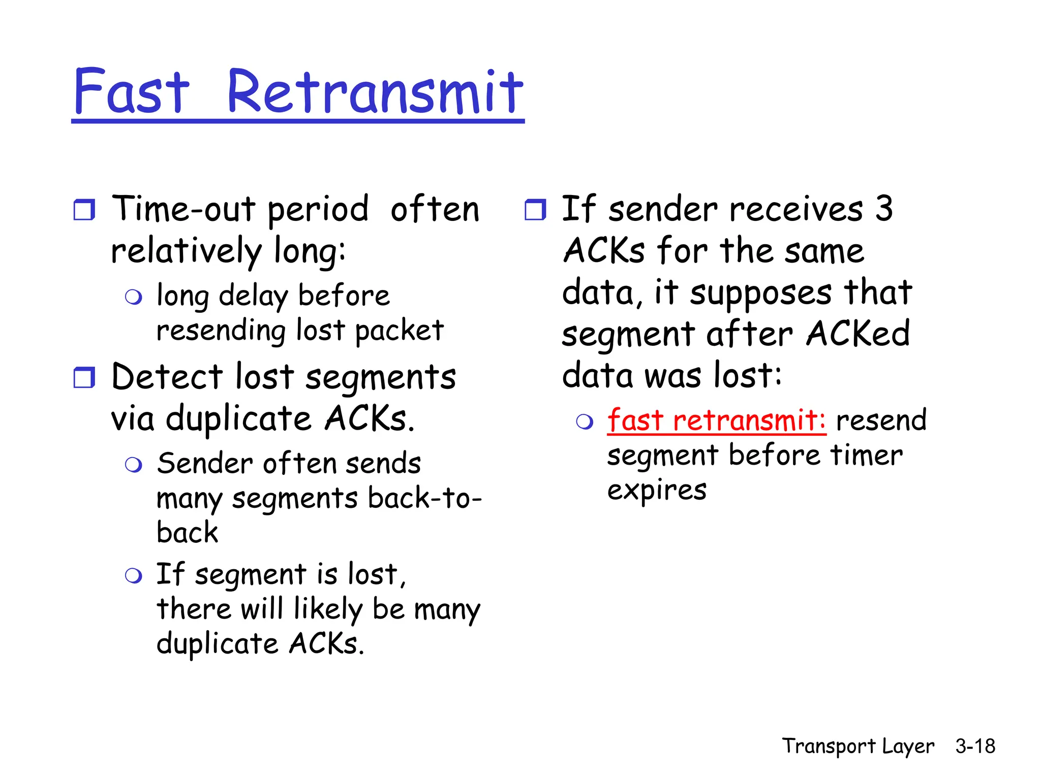
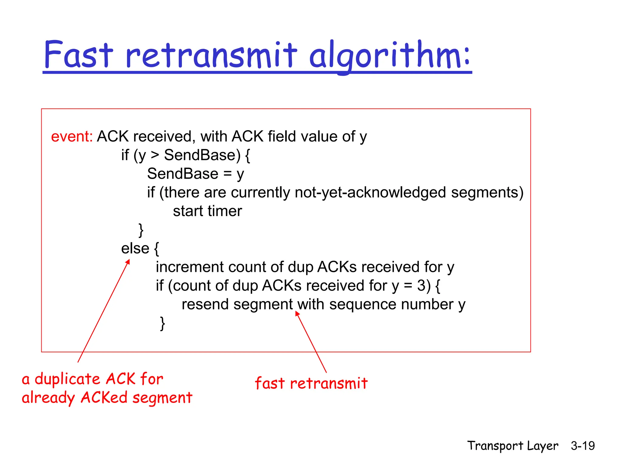
- Mechanisms for reliable data transfer like cumulative acknowledgements, timeouts, and retransmissions.
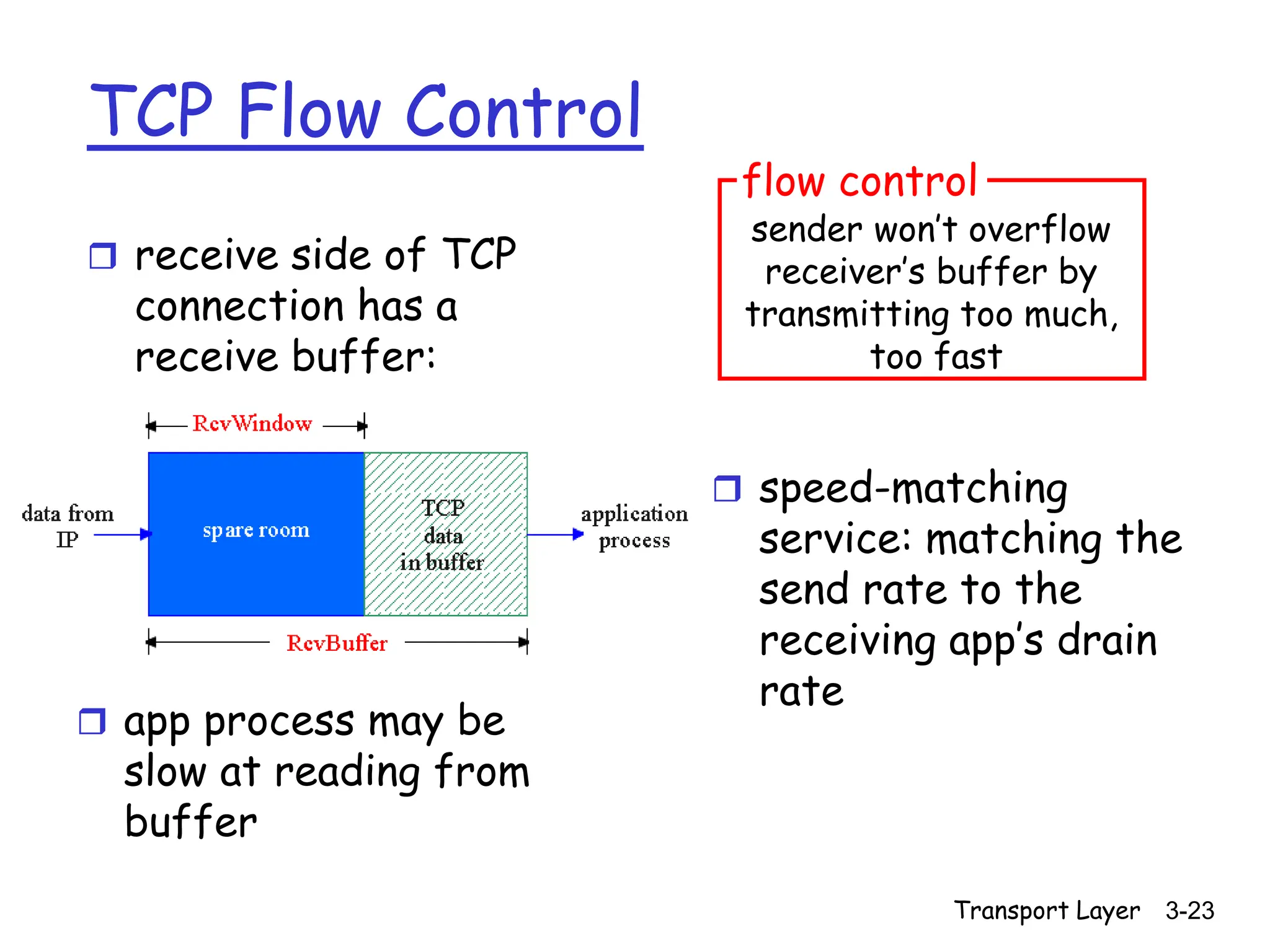
- Flow control using advertised receive windows to limit unacknowledged data.
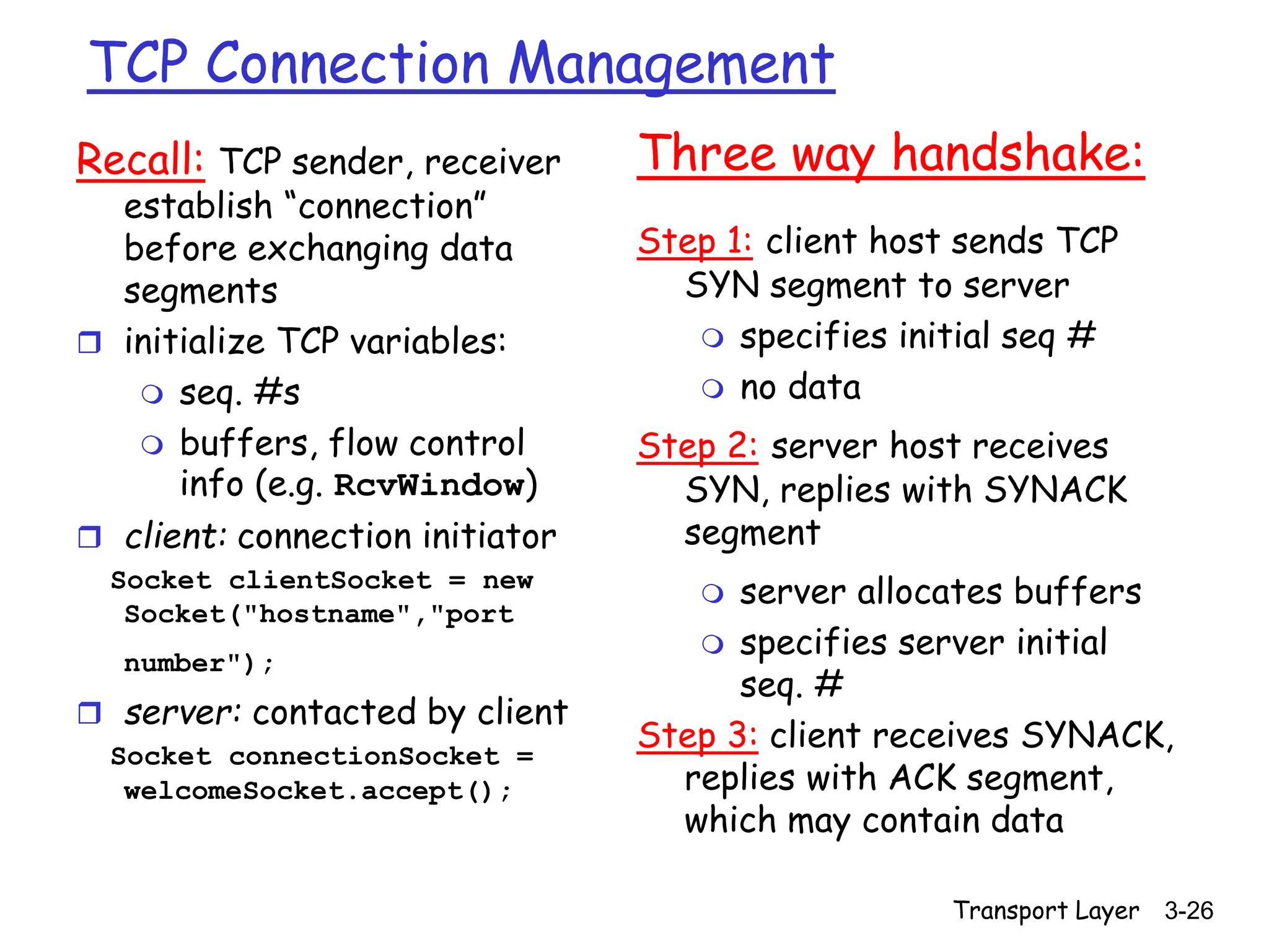
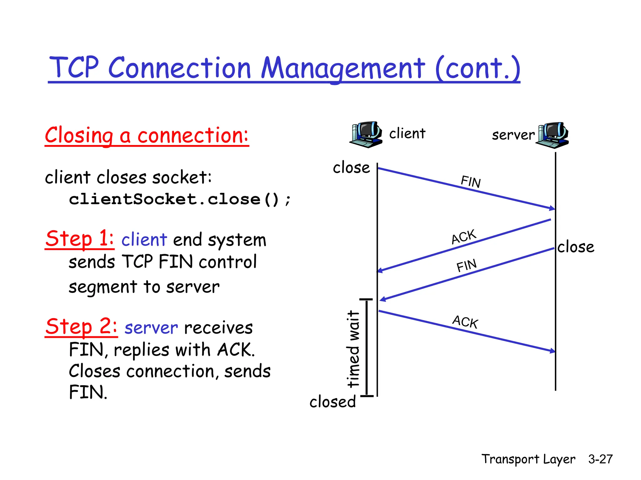
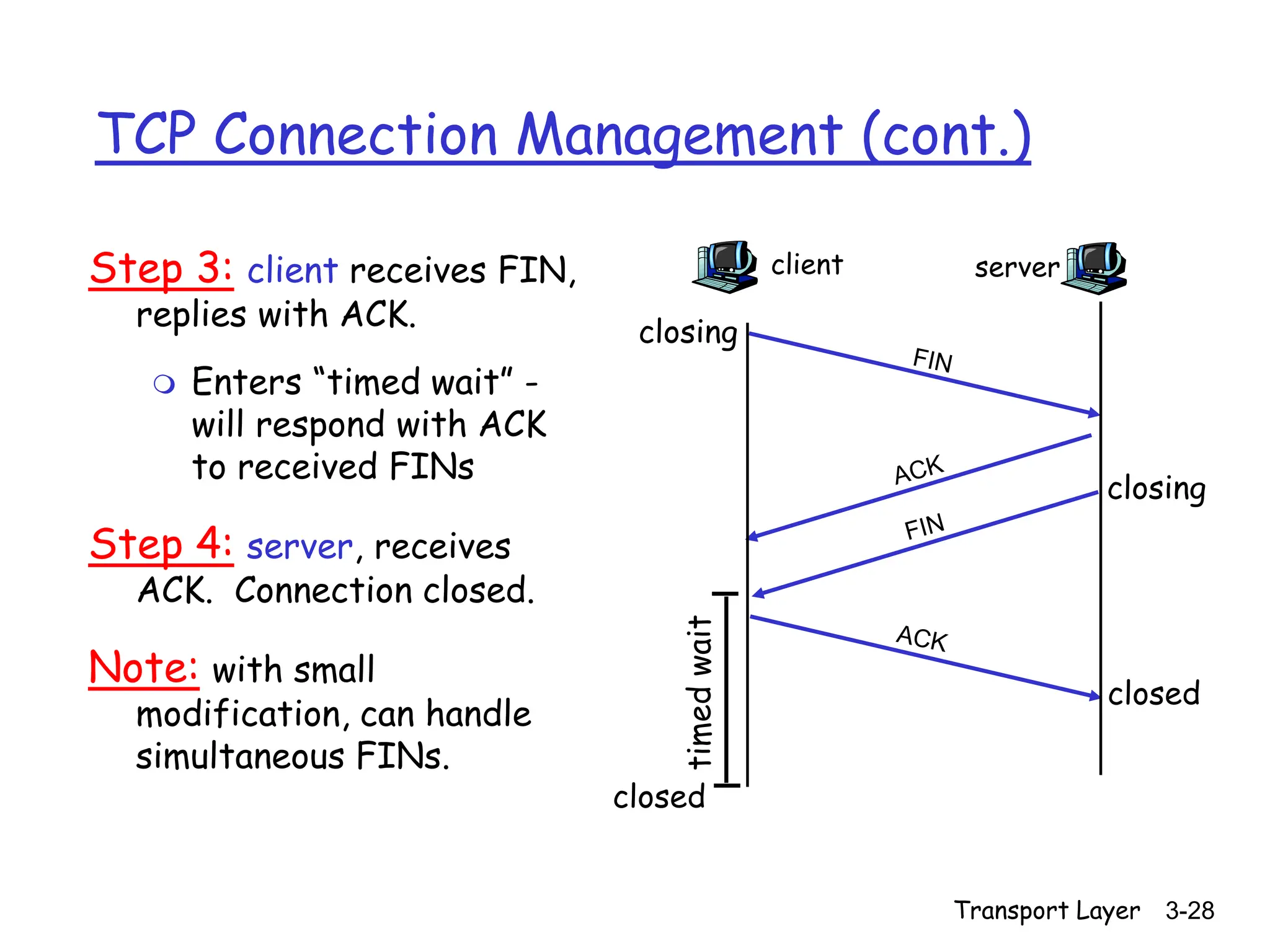
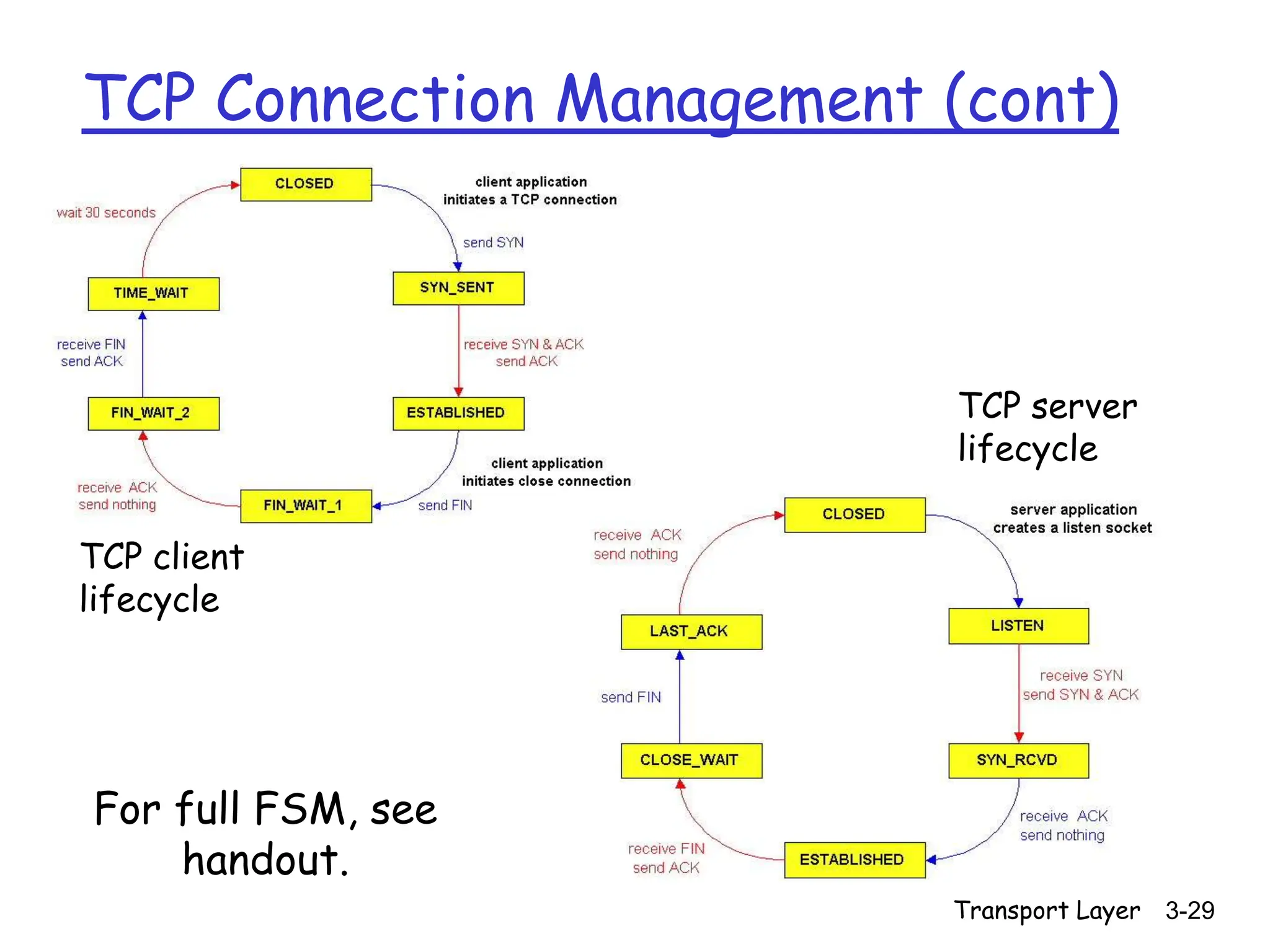
- Connection management using three-way handshakes to initialize connections and four-way handshakes to close connections in an orderly manner.
![Transport Layer 3-17
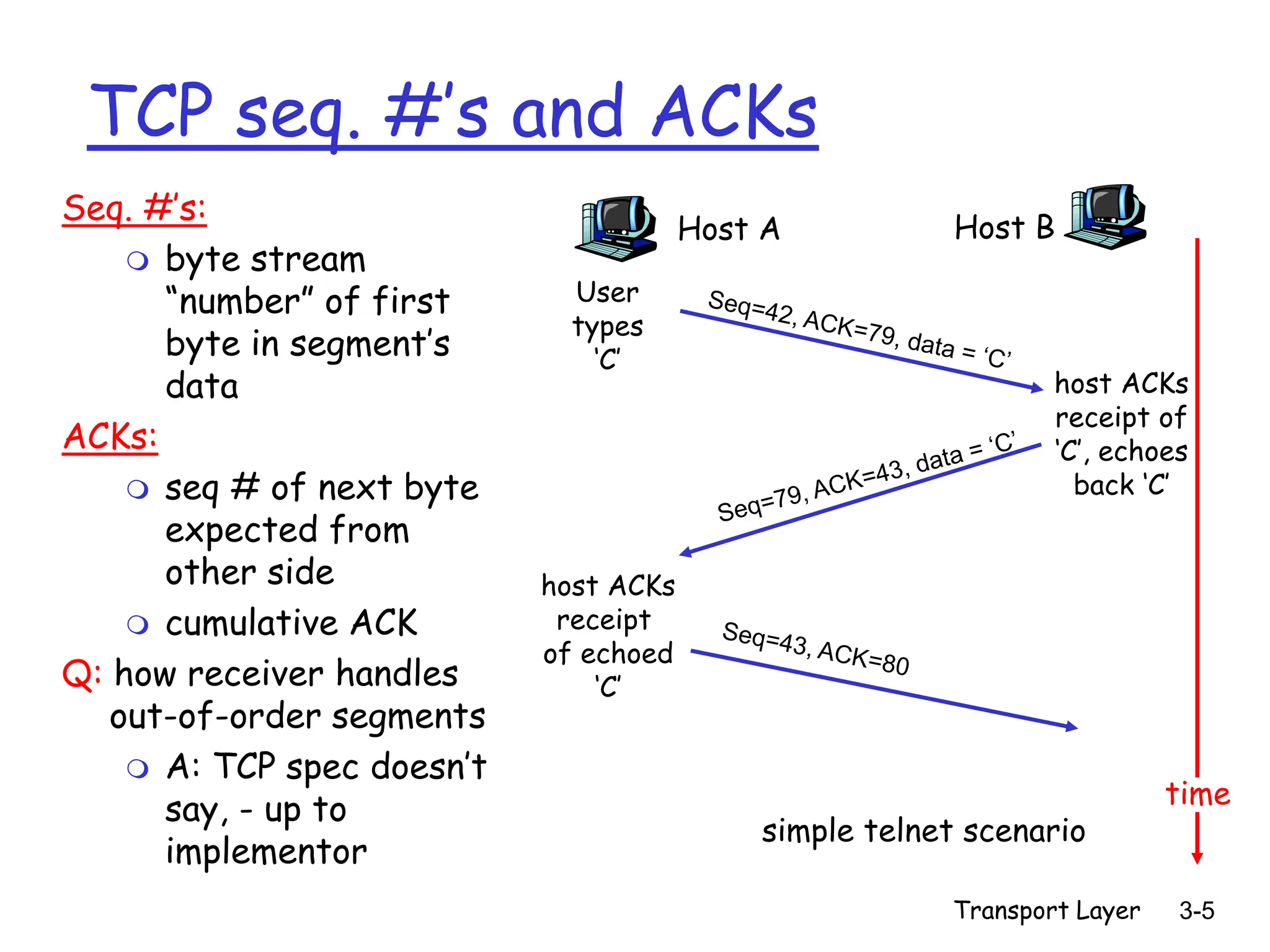
TCP ACK generation [RFC 1122, RFC 2581]
Event at Receiver
Arrival of in-order segment with
expected seq #. All data up to
expected seq # already ACKed
Arrival of in-order segment with
expected seq #. One other
segment has ACK pending
Arrival of out-of-order segment
higher-than-expect seq. # .
Gap detected
Arrival of segment that
partially or completely fills gap
TCP Receiver action
Delayed ACK. Wait up to 500ms
for next segment. If no next segment,
send ACK
Immediately send single cumulative
ACK, ACKing both in-order segments
Immediately send duplicate ACK,
indicating seq. # of next expected byte
Immediate send ACK, update next
Expected byte](https://image.slidesharecdn.com/kandrtcp1-240313091152-72b2ebbf/75/KandR_TCP-1-ppt-notes-for-congestion-control-17-2048.jpg)
![Transport Layer 3-24
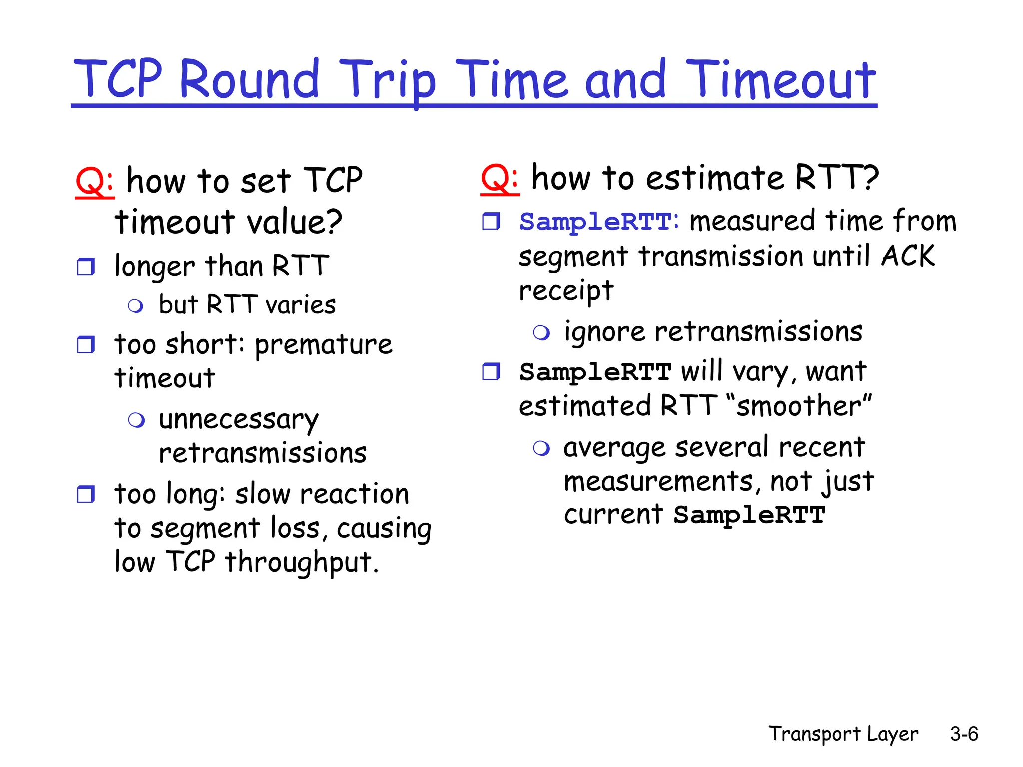
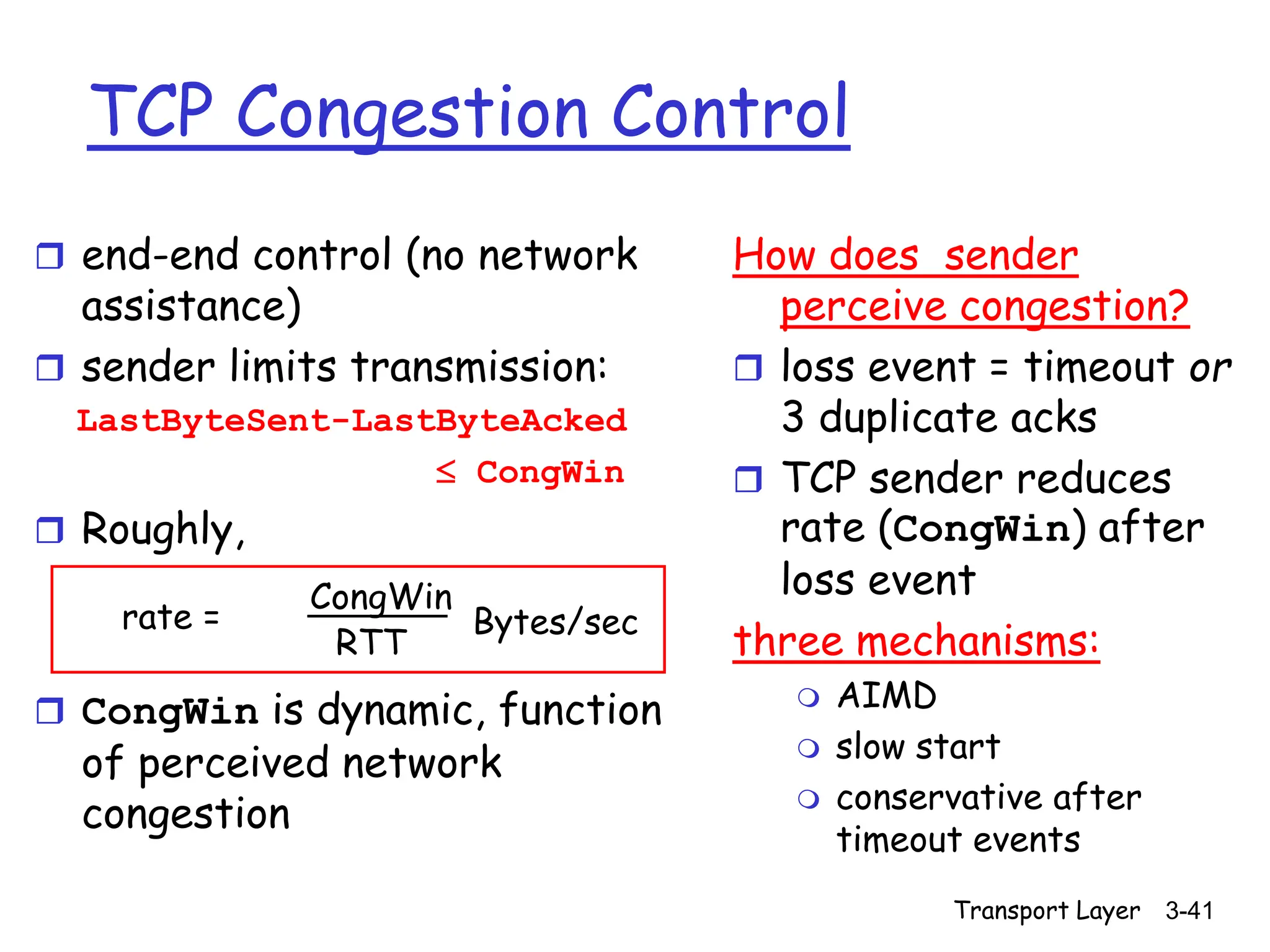
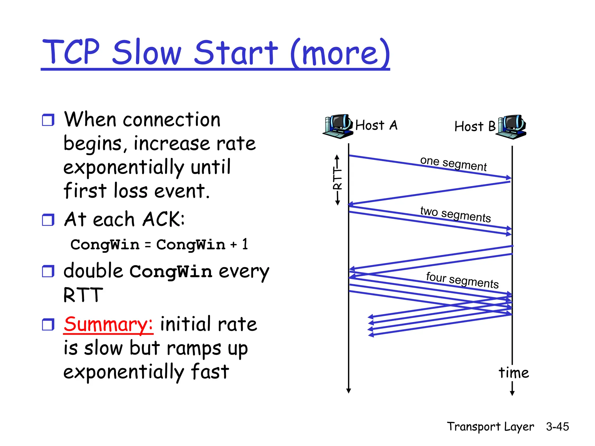
TCP Flow control: how it works
(Suppose TCP receiver
discards out-of-order
segments)
spare room in buffer
= RcvWindow
= RcvBuffer-[LastByteRcvd -
LastByteRead]
Rcvr advertises spare
room by including value
of RcvWindow in
segments
Sender limits unACKed
data to RcvWindow
guarantees receive
buffer doesn’t overflow](https://image.slidesharecdn.com/kandrtcp1-240313091152-72b2ebbf/75/KandR_TCP-1-ppt-notes-for-congestion-control-24-2048.jpg)


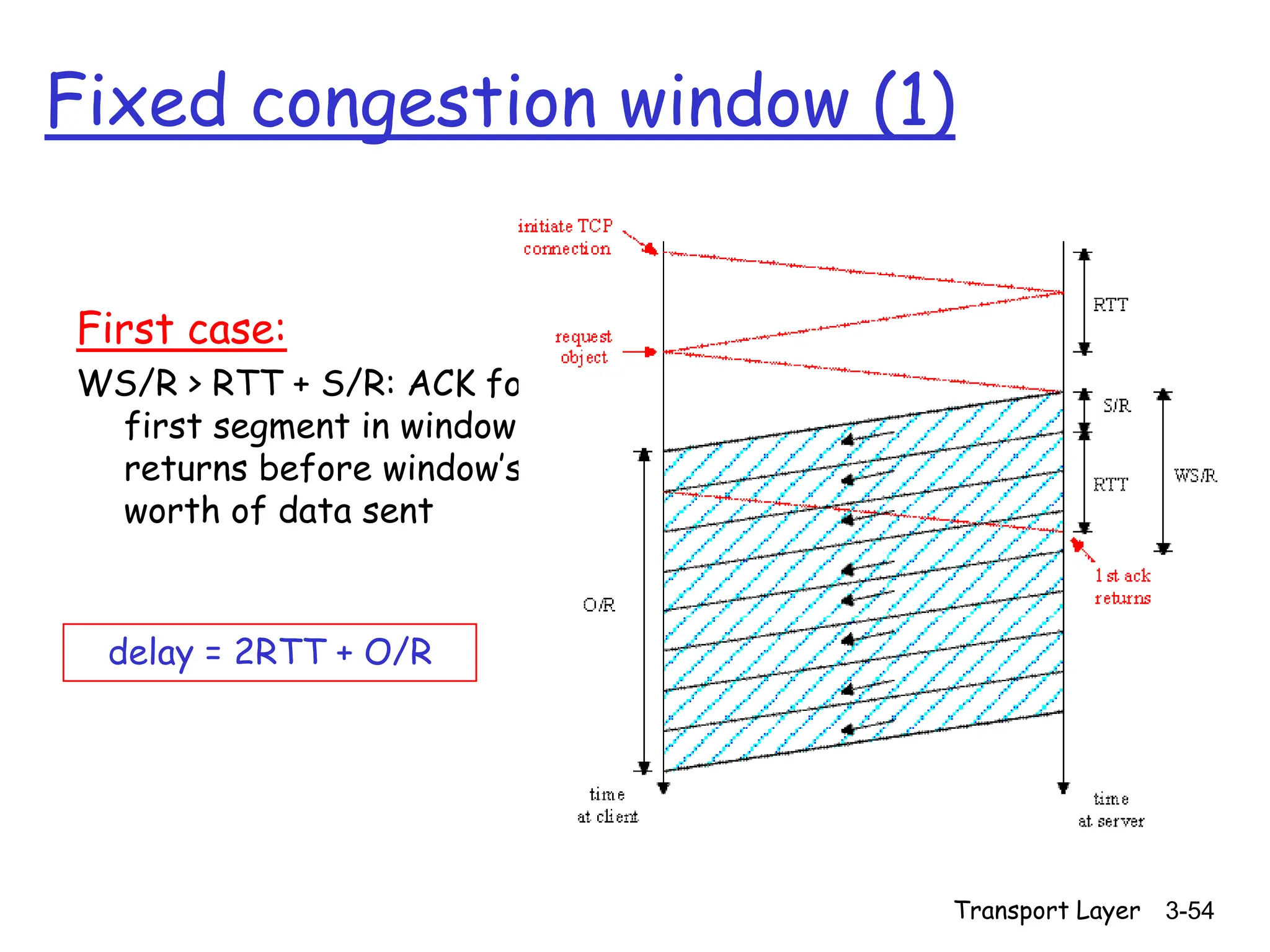
![Transport Layer 3-55
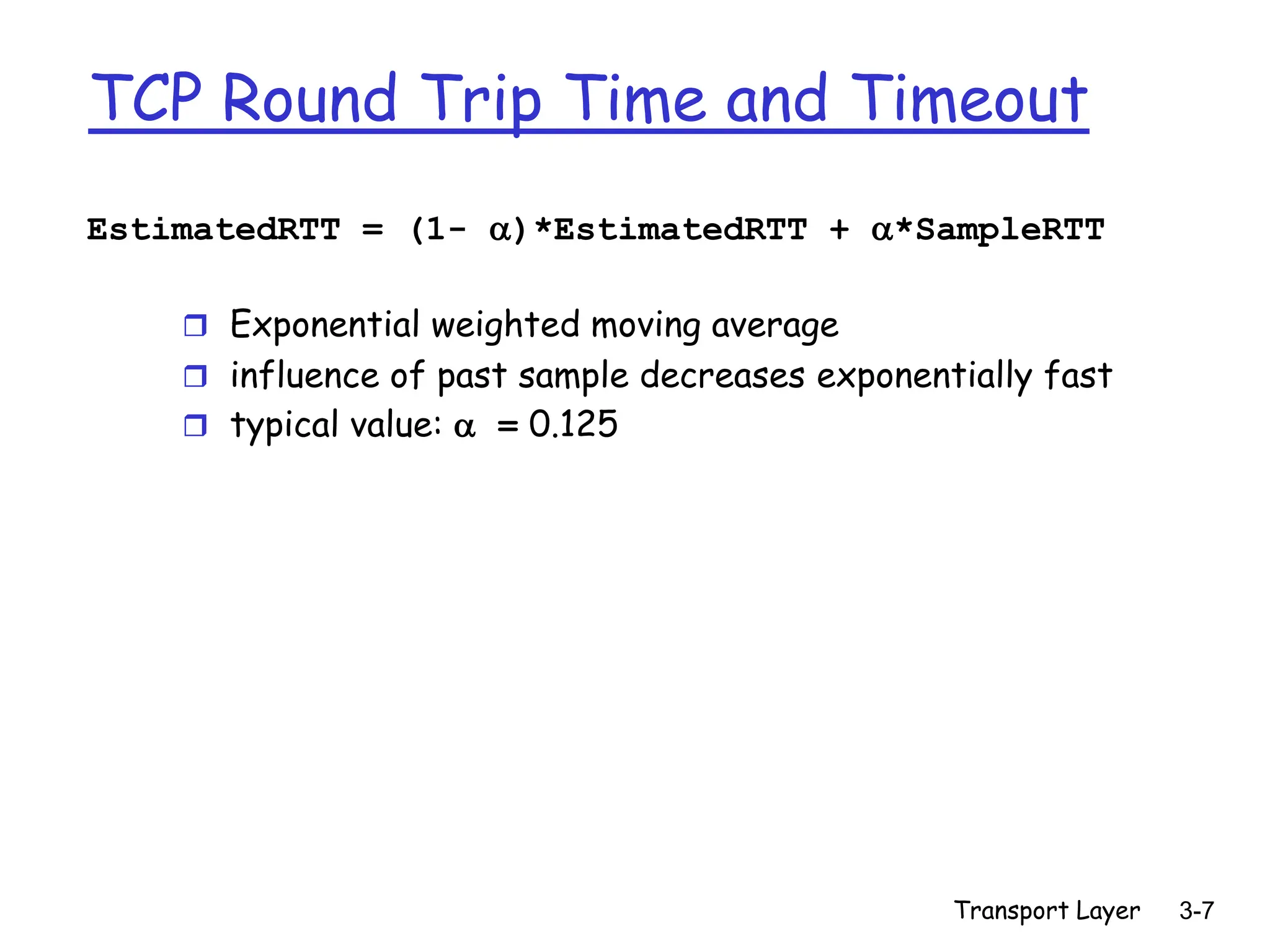
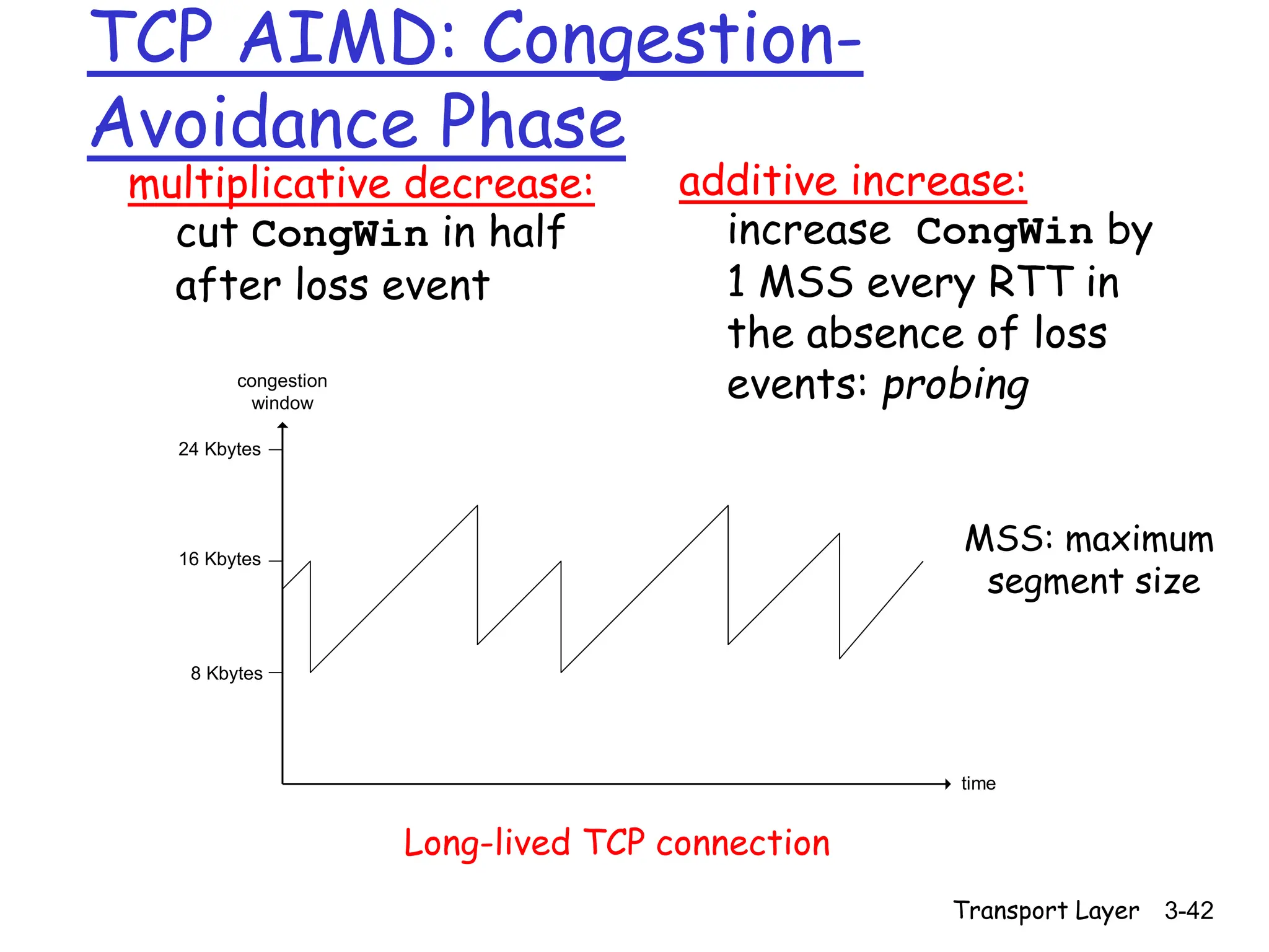
Fixed congestion window (2)
Second case:
WS/R < RTT + S/R: wait
for ACK after sending
window’s worth of data
sent
delay = 2RTT + O/R
+ (K-1)[S/R + RTT - WS/R]
K = O/WS: number of windows
Required to transmit O
RTT – (W-1)S/R is server idle time](https://image.slidesharecdn.com/kandrtcp1-240313091152-72b2ebbf/75/KandR_TCP-1-ppt-notes-for-congestion-control-55-2048.jpg)
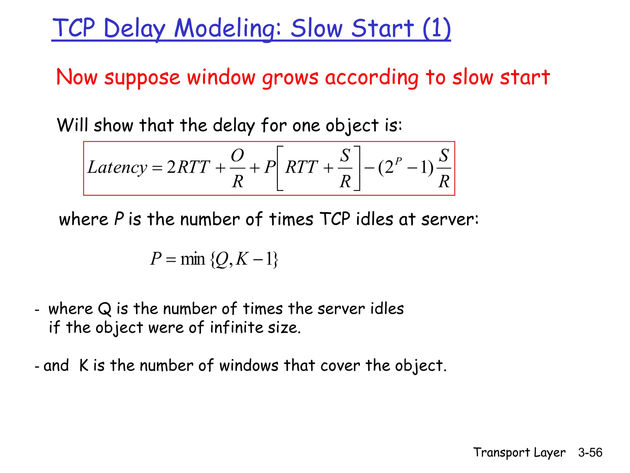
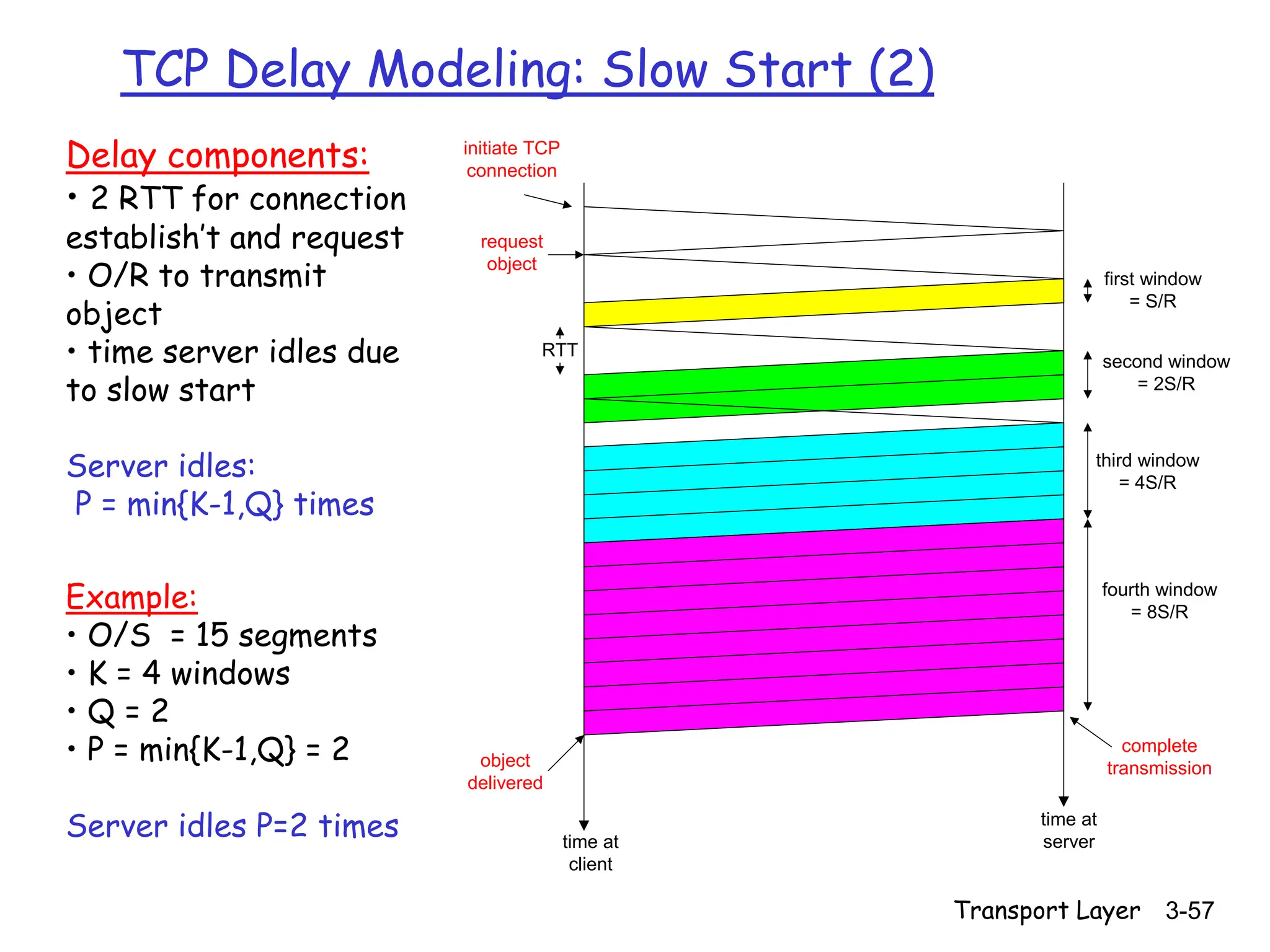
![Transport Layer 3-58
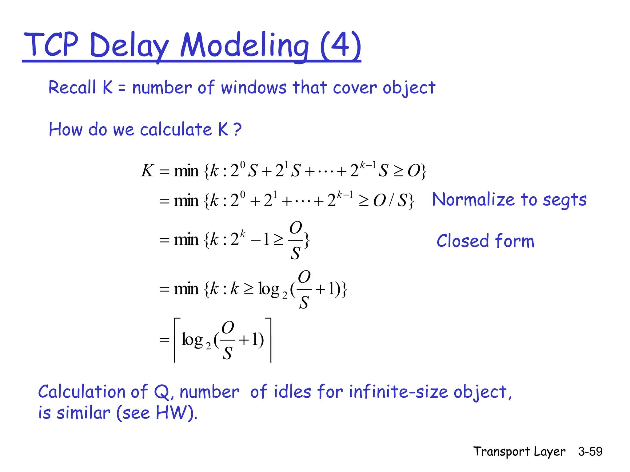
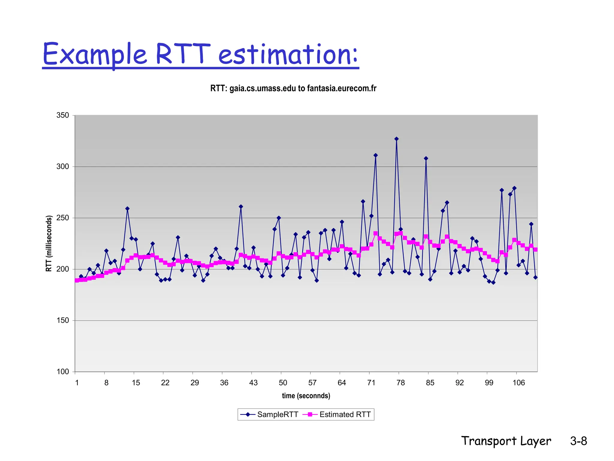
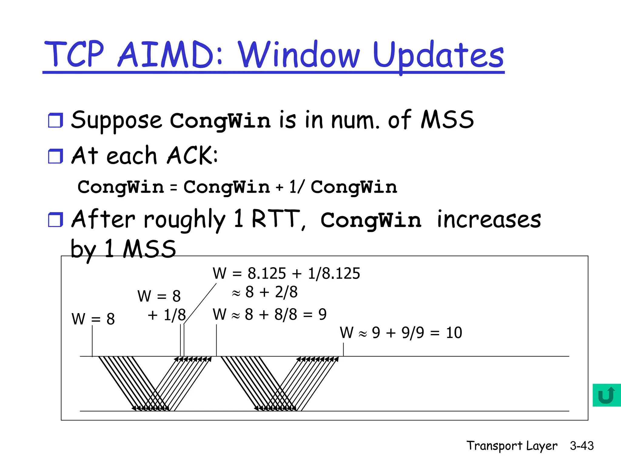
TCP Delay Modeling (3)
R
S
R
S
RTT
P
RTT
R
O
R
S
RTT
R
S
RTT
R
O
idleTime
RTT
R
O
P
k
P
k
P
p
p
)
1
2
(
]
[
2
]
2
[
2
2
delay
1
1
1
th window
after the
time
idle
2 1
k
R
S
RTT
R
S k
ement
acknowledg
receives
server
until
segment
send
to
starts
server
when
from
time
RTT
R
S
window
kth
the
transmit
to
time
2 1
R
S
k
RTT
initiate TCP
connection
request
object
first window
= S/R
second window
= 2S/R
third window
= 4S/R
fourth window
= 8S/R
complete
transmission
object
delivered
time at
client
time at
server
= Cycle time – sending time
= Cycle time
= sending time
(note + means >= 0)
= Obj Tx Time + setup + idle time](https://image.slidesharecdn.com/kandrtcp1-240313091152-72b2ebbf/75/KandR_TCP-1-ppt-notes-for-congestion-control-58-2048.jpg)