Download to read offline
![International Research Journal of Engineering and Technology (IRJET) e-ISSN: 2395 -0056
Volume: 04 Issue: 03 | Mar -2017 www.irjet.net p-ISSN: 2395-0072
© 2017, IRJET | Impact Factor value: 5.181 | ISO 9001:2008 Certified Journal | Page 1654
1.4 Methodology:
Steps In Methodology:
1. Study and analysis of working of conventional
steering mechanism of automobile steeringsystem.
2. Study the various research papers published in this
field.
3. Based upon this design and model a unitof easyand
with minimum effort steering system for an
automobile.
4. Select the appropriatematerialsofunitcomponents
and study various properties of it.
5. Manufacturing of the components of the system.
6. Perform trial and analyze it.
7. Compare the conventional steering system and
developed steering system.
2. LITERETURE REVIEW
[1] Mateusz Kukla et al, (2016) Motor is a device used for
converting electrical energy into mechanical energy i.e.
rotation of shaft at output. Various types of motors are
available as per requirement. A stepper motor converts
electrical signals in form of impulses into the angle of
rotation. This relation is proportional so the speed of motor
is dependent on frequency of impulse. The higher value of
rotational speed results in lower torque of stepper motor –
this value is connected with the value of current intensity.
[2] Tatyaso A. Garande et al, (2013) described that there
are many people who cannot do their day to day activity on
their own due to their disability. So they can use wheel chair
which are automated and require less effort. This can be
done by providing joystick or by Deicticapproach.Joystick is
displaced by user in the direction he wants to go. The
joystick used is of resistance type. Another way is Deictic
approach in this vision of environment is used for
controlling. If user wants to move from one place toanother,
he points the location where he wants to move and wheel
chair goes to the pointed location automatically.
[3] Robin Burgess-Limerick et al, (2013) described that
the joystick controls the rate of change of steering angle
instead of directly changing the steering angle.Bydisplacing
the joystick at constant rate the steering anglealsoincreases
constantly. Until the joystick is bring to origin that is center
position, the steering angle changes. To get maximum
steering deviation we must hold joystick away from center
for long time. Its main advantage is that we can achieve
sensitivity for control over a large range of the displacement
of joystick.
3. SIMULATION WORK
3.1 Selection of Joystick
There are two types of joystick:-
1. Analog Joystick :
The directional interface required to map specific
directions of movement on to specific buttons on
the controller. In this type of joystick we do not get
variable output. It means when we press the button
we get maximum output.
INITIAL STUDY
MATERIAL SELECTION
DESIGN OF MACHINE COMPONENTS
MODELLING
EXPERIMENTAL SET UP
ANALYSIS OF RESULT
CONCLUSION
Fig. 1.4.1 - Flow Diagram of Methodology](https://image.slidesharecdn.com/irjet-v4i3381-171228091931/85/Joystick-Operated-Steering-System-2-320.jpg)
![International Research Journal of Engineering and Technology (IRJET) e-ISSN: 2395 -0056
Volume: 04 Issue: 03 | Mar -2017 www.irjet.net p-ISSN: 2395-0072
© 2017, IRJET | Impact Factor value: 5.181 | ISO 9001:2008 Certified Journal | Page 1655
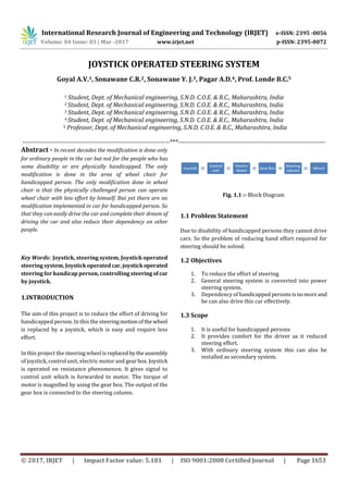
Fig. 3.1.1 :- Analog Joystick[4]
2. Resistance Joystick :
The lever is fixed at a single point, normally in
accordance with the principle of a ball-and-socket
joint, which gives the lever its two degrees of
freedom. This type of joystick work on resistance
phenomenon. As the resistance is varied we get
variable output.
Fig. 3.1.2 :- Resistance Joystick[2]
From studying the above two types of joystick we see that
resistance joystick is more compatible with our system. So
we select the resistance type joystick.
3.2 Design of Gear Box
Material Selection:-
Gear material :- EN18.
Pinion material :- EN18.
Input Parameters :-
(sut)g = (sut)p = 930 N/mm2
(syt)g = (syt)p = 735 N/mm2
Zp = 32
Zg = 96
G = 3
Hardness = 207 BHN
From PSG design data book, page number 8.50 and 8.51.
We get values of spur gear and pinion pair for gear ratio 3.
we can find ,
Beam strength calculations:-
σb = (sut)/ 3, = (930)/3 , = 310 N/mm2
For 200 involute gear,
Yp = 0.154 – (0.192/ Zp)
Yp = 0.154 – (0.192/ 32)
Yp = 0.1255.
σb * Yp = 310*0.1255 = 44.795 N/mm2
Yg = 0.154 – (0.192/ Zg)
Yg = 0.154 – (0.192/ 96)
Yg = 0.1445.
σb * Yg =310*0.1445 = 38.905 N/mm2
As (σb * Yp) < ( σb * Yg), we will design the gear pair for
pinion
Fb = σb *b*m*Yp
Fb = 310*12*m*m*0.1255
Fb = 466.86*m2 N ……… (1)
Wear strength calculations:-
dp = m* Zp = 32*m
For external gear pair,
Q = (2* Zg ) / (Zg + Zp)
Q = (2* 96) / (96+ 32)
Q = 1.5
K = 0.16 *(BHN / 100)2
K = 0.16 *(207/ 100)2
K = 0.16 *(BHN / 100)2
K = 0.6855](https://image.slidesharecdn.com/irjet-v4i3381-171228091931/85/Joystick-Operated-Steering-System-3-320.jpg)
![International Research Journal of Engineering and Technology (IRJET) e-ISSN: 2395 -0056
Volume: 04 Issue: 03 | Mar -2017 www.irjet.net p-ISSN: 2395-0072
© 2017, IRJET | Impact Factor value: 5.181 | ISO 9001:2008 Certified Journal | Page 1657
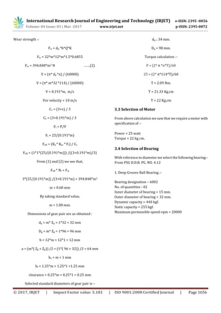
4. OUTLINE DIAGRAM
5. CONCLUSION
By this the person whoarehandicappedorhaveless
strength in their hand can drive this car. The conventional
steering system performs as power steering system. The
effort required by common man for steering the wheel is
also eliminated. This system can also be installed as
secondary system in cars. The dependency of handicapped
person on other persons reduces.
6. REFRENCES
[1] Mateusz Kukla, Pawel Tarkowski, Ireneusz Malujda,
Krzysztof Talaska, Jan Gorecki, “Determination of the
torque characteristics of a stepper motor”, Procedia
Technology, Vol.136, pp. 375 – 379, ( 2016 ).
[2] Tatyaso A. Garande, Prof. P.D. Sonawane, Prof. Dr.
S.T.Chavan, Prof. G. S. Barpande, “Review of Motorized
Tricycle for the Disabled Person”, pp. 316-320, (2013).
[3] Robin Burgess-Limerick, Christine Zupanc , Guy Wallis,
“Effect of Control Order on Steering a Simulated
Underground Coal Shuttle Car”, Applied Ergonomics,
Vol. 44, pp. 225 – 229, (2013).
[4] Takeda et al, “Operating Device With Analog Joystick”,
US006102803A, Aug. 15, (2000).
[5] Faculty of Mechanical Engineering, Design Data Book,
Edition 1978,PSGCollegeof Technology,Coimbtore-641
004, pp. 8.43 – 8.54.](https://image.slidesharecdn.com/irjet-v4i3381-171228091931/85/Joystick-Operated-Steering-System-5-320.jpg)

This document describes a joystick-operated steering system for cars to assist handicapped individuals. The system replaces the conventional steering wheel with a joystick, control unit, electric motor, and gearbox. The joystick provides signals to the control unit which powers the motor. The gearbox magnifies the motor's torque and connects to the steering column. The system aims to reduce the effort required for steering to allow handicapped people to drive independently. It discusses the design of the gearbox components, selection of a suitable joystick, motor specifications, and bearing selection. The conclusion states that this system enables handicapped individuals to drive with less strength and reduces their dependency on others.