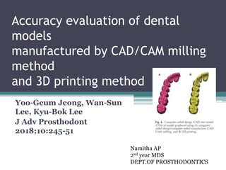
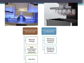
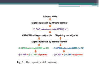
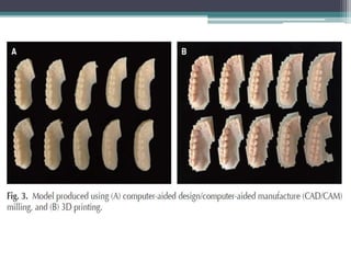
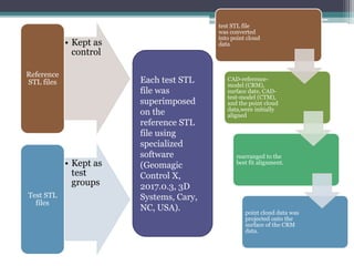
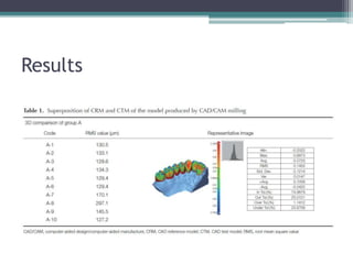
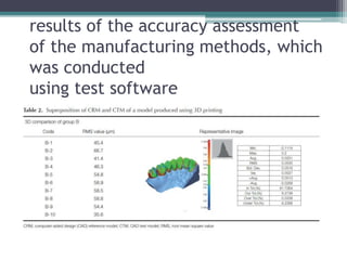
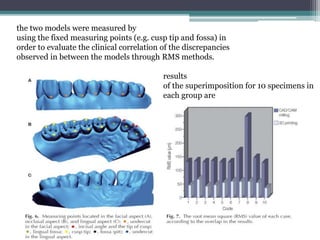
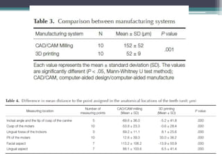
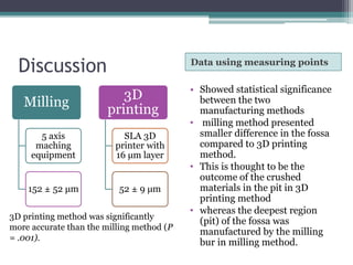
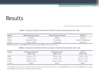
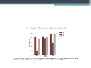
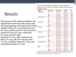
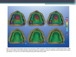
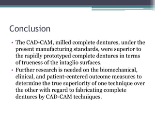
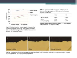
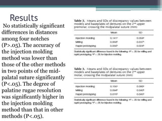
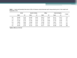
Accuracy evaluation of dental
models
manufactured by CAD/CAM milling
method
and 3D printing method
Yoo-Geum Jeong, Wan-Sun
Lee, Kyu-Bok Lee
J Adv Prosthodont
2018;10:245-51
Namitha AP
2nd year MDS
DEPT.OF PROSTHODONTICS
CONTENTS
• INTRODUCTION
• AIM
• MATERIALS AND METHODS
• RESULTS
• DISCUSSION
• RELATED ARTICLES
• CONCLUSION
• REFERENCES
INTRODUCTION
Taking a dental
impression
TRADITIONAL
METHODS
Affected by skill
level and
technique of
practitioner
DIGITAL
METHODS
CAD CAM
MILLING
3D PRINTING
DISADVANTAGES
OF CAD CAM
Material
wastage
high
maintenance
cost of the
equipment
time loss
ADVANTAGES OF
3D PRINTING
Minimum
amount of
material
Maximum
number of
products
AIM
• To evaluate the accuracy of a model made using
the computer-aided design/computer-aided
manufacture (CAD/CAM) milling method and
3D printing method and to confirm its
applicability as a work model for dental
prosthesis production
MATERIALS AND METHODS
• scanned using an oral scanner
natural tooth model (ANA-4,Frasaco, Germany)
• From obtained scan data
CAD Reference Model(CRM)
• 10 each using milling method and 3D printing method
Total 20 models
• CAD test model was formed
20 models were then scanned using a desktop
scanner
Synthetic resin
Denture model
Negative model
using dental
silicone
Model cast using
hard plaster
reference STL file
CAD Reference
Model(CRM)
Intra oral scanner
Trios (3Shape,
Copenhagen,
Denmark).
10 Milling Models
with PMMA
blocks
10 3D Printed
models
Desktop scanner
• Kept as
control
Reference
STL files
• Kept as
test
groups
Test STL
files
Each test STL
file was
superimposed
on the
reference STL
file using
specialized
software
(Geomagic
Control X,
2017.0.3, 3D
Systems, Cary,
NC, USA).
test STL file
was converted
into point cloud
data
CAD-reference-
model (CRM),
surface date, CAD-
test-model (CTM),
and the point cloud
data,were initially
aligned
rearranged to the
best fit alignment.
point cloud data was
projected onto the
surface of the CRM
data.
The
distances between surface data and all
points were converted
to root mean square (RMS) values. The
RMS is a general
method to assess the mean value of errors,
by directly comparing
two data groups with an identical
coordinate system.
The accuracy of a corresponding data
group can be calculated
using a single scale. A higher calculated
RMS value
indicated a large error, i.e., the difference
in the attributes
between reference and measurement data.
The RMS is typically
used as a criterion to measure the
similarity of two sets
of N-dimensional vector sets after optimal
superimposition.
Unnecessary and inaccurate parts of the 3D shape data
of all models were eliminated.The superimposition results
were illustrated as a color difference map
Max +100µm
Min -100µm
Effective range(green)
-30 μm to +30 μm.
42
assigned
points
Incisal
angle of
incisors(4)
Cusp of the
molars(10)
Undercut
in the
facial
aspect(7)
Undercut
in the
lingal
aspect(7)
Fossa/pit
of
molars(10)
Lingual
fossa of
incisors(3)
Tip of cusp
of
canine(1)
For the location
of these points, the divergences in the x-, y-, and z-axis to
each reference and the test data were measured.15
Results
results of the accuracy assessment
of the manufacturing methods, which
was conducted
using test software
the two models were measured by
using the fixed measuring points (e.g. cusp tip and fossa) in
order to evaluate the clinical correlation of the discrepancies
observed in between the models through RMS methods.
results
of the superimposition for 10 specimens in
each group are
Discussion Data using measuring points
Milling
5 axis
maching
equipment
152 ± 52 μm
3D
printing
SLA 3D
printer with
16 µm layer
52 ± 9 μm
• Showed statistical significance
between the two
manufacturing methods
• milling method presented
smaller difference in the fossa
compared to 3D printing
method.
• This is thought to be the
outcome of the crushed
materials in the pit in 3D
printing method
• whereas the deepest region
(pit) of the fossa was
manufactured by the milling
bur in milling method.
3D printing method was significantly
more accurate than the milling method (P
= .001).
color difference maps of two models
were analyzed
using inspection software
• compared to group B, group A
showed red and blue areas in
the occlusal surface,
interdental space, and gingival
sulcus.
• inferior to 3D printing, in
terms of the reproducibility
ofthese regions (i.e., the
interdental space, gingival
sulcus, and occlusal surface).
CRITICAL EVALUATION
• the minimumNthickness of the bur was 1 mm in the milling
process, which limited the accurate reproduction of shapes
that were smaller than 1 mm.
• bur of less than 1 mm could not be used since PMMA resin
was used as the milling material to produce the model. Since
burs less than 1 mm (e.g., 0.6mm) are easily heated, this
would have caused the resin to be melted and adsorbed onto
the bur, fracturing the bur in the process.
• data locations for the manufacture of a working model were
selected on the CAM software before machining so that two
models were arranged per single block. Although this
arrangement was chosen to prevent the fracture of the bur
and reduce the number of machining processes, it could have
also affected the accuracy of the model.
CONCLUSION
• The current study demonstrated that models
manufactured by the 3D printing method were
more accurate than those manufactured by the
milling method, within the limitations of the
study. However, currently, it is still challenging
to apply the models manufactured by milling
and 3D printing method as working models for
dental prostheses manufacture.
RELATED ARTICLES
Accuracy of dental models
fabricated
by CAD/CAM milling method and
3D
printing method.
Wook-Tae Kim.
J Oral Res 2018; 7(4):127-133.
Aim of the study
to evaluate the accuracy of a dental model fabricated
using the CAD/CAM milling method and the 3D printing
method.
Materials and methods
Digitisation of master model using intra oral scanner
manufacturing of working models (milling model, Multi-
jet printing model and Color-jet printing model) by using
the scan data of the master model
e digitization of the working model by using a laboratory
scanner, the superimposition of the digital data of the
master model and working models using inspection
software
3-dimensional analysis.
Ten measurements per group were done by
one practitioner
Results
Conclusion
• Dental models manufactured by the CAD/CAM
milling method presented superior accuracy
over the models manufactured by the 3D
printing method. Therefore, the use of optimized
CAD software and appropriate materials is
crucial for the fabrication accuracy of dental
models.
Evaluation of internal fit of interim
crown fabricated with CAD/CAM
milling and 3D printing system
Wan-Sun Lee
Du-Hyeong Lee
Kyu-Bok Lee
J Adv Prosthodont 2017;9:265-70
Aim of the study
to evaluate the internal fit of the crown manufactured
by CAD/CAM milling method and 3D printing method.
Materials and methods
The master model was fabricated with
stainless steel by using CNC machine and
the work model was created from the vinyl-
polysiloxane impression
After scanning
the working
model, the
design software
is used to
design the
crown.
The saved STL file
is used on the
CAD/CAM milling
method and two
types of 3D printing
method to produce
10 interim crowns
per group.
Internal discrepancy measurement uses the
silicon replica method and the measured
data are analyzed with One-way ANOVA to
verify the statistic significance.
The discrepancy means (standard deviation) of the 3
groups are 171.6 (97.4) μm for the crown manufactured
by the milling system and 149.1 (65.9) and 91.1 (36.4)
μm, respectively, for the crowns manufactured with the
two types of 3D printing system. There was a statistically
significant difference and the 3D printing system group
showed more outstanding value than the milling system
group.
Results
Conclusion
• The marginal and internal fit of the interim
restoration has more outstanding 3D printing
method than the CAD/CAM milling method.
Therefore, the 3D printing method is considered
as applicable for not only the interim restoration
production, but also in the dental prosthesis
production with a higher level of completion.
CAD-CAM milled versus rapidly
prototyped (3D-printed)
complete dentures: An in vitro
evaluation of trueness
Nicole Kalberer,
Albert Mehl,
Martin Schimmel,
Frauke Müller,
Murali Srinivasan,
(J Prosthet Dent 2018)
Aim of the study
to compare the differences in trueness between the CAD-CAM milled and 3D-printed
complete dentures.
Materials and methods
third scan (after the wet-dry cycle) was then made after 21 days, during which the complete dentures
were maintained in the artificial saliva solution during the day and stored dry at night.
immersed in an artificial saliva solution for a period of 21 days, followed by a second scan (after
immersion in saliva).
intaglio surfaces of the fabricated complete dentures were scanned at baseline using a laboratory
scanner.
Two groups of identical maxillary complete dentures were fabricated
3D-printed denture group (3DPD) (n=10) milled denture group (MDG) (n=10)
• A purpose-built 3D
comparison software program
was used to analyze the
differences in the trueness of
the complete dentures. The
analyses were performed
• Independent t tests, ANOVA,
and post hoc tests were used
for statistical analyses (a=.05).
Entire
intaglio
surface
Mid palatal
raphe
Vestibular
flange
Anterior
ridge
Posterior
crest
Palatal vault
Posterior
palatal seal
area
tuberosity
Results
The trueness of the milled prostheses was
significantly better than that of the rapid
prototyping group with regard to the entire
intaglio surface (P<.001), posterior crest
(P<.001), palatal vault (P<.001), posterior
palatal seal area (P<.001), tuberosity
(P<.001), anterior ridge
(baseline: P<.001; after immersion in
saliva: P=.001; after the wet-dry cycle:
P=.011), vestibular flange (P<.001), and
mid-palatal raphae (P<.001).
Conclusion
• The CAD-CAM, milled complete dentures, under the
present manufacturing standards, were superior to
the rapidly prototyped complete dentures in terms
of trueness of the intaglio surfaces.
• Further research is needed on the biomechanical,
clinical, and patient-centered outcome measures to
determine the true superiority of one technique over
the other with regard to fabricating complete
dentures by CAD-CAM techniques.
Comparing accuracy of denture
bases fabricated by injection
molding, CAD/CAM milling, and
rapid prototyping method
Suji Lee
Seoung-Jin Hong
Janghyun Paek
Ahran Pae
Kung-Rock Kwon
Kwantae Noh
Aim of the study
• . The accuracy of denture bases was compared
among injection molding, milling, and rapid
prototyping (RP) fabricating method
The maxillary edentulous master cast was fabricated and round
shaped four notches were formed. The cast was duplicated to ten
casts and scanned. Denture bases were milled from a pre-polymerized
block in the milling method. In the RP method, denture bases were
printed and post-cured.
In the injection molding method,
designed denture bases were milled
from a wax block and fabricated using
SR Ivocap injection system.
The intaglio
surface of the
base was
scanned and
surface
matching
software was
used to
measure
inaccuracy
Measurements were performed
between four notches and two points
in the mid-palatal suture to evaluate
inaccuracy. The palatine rugae
resolution was evaluated.
Measurements were performed between two
points in the mid-palatal suture to evaluate
inaccuracy. The palatine rugae resolution was
evaluated.
Results
No statistically significant
differences in distances
among four notches
(P>.05). The accuracy of
the injection molding
method was lower than
those of the other methods
in two points of the mid-
palatal suture significantly
(P<.05). The degree of
palatine rugae resolution
was significantly higher in
the injection molding
method than that in other
methods (P<.05).
Conclusion
• Overall accuracy of the denture base is higher in
milling and RP method than the injection
molding method. The degree of fine
reproducibility is higher in the injection molding
method than the milling or RP method.
REFERENCES
THANK YOU!!!

Journal club PROSTHODONTICS

  • 1.
    Accuracy evaluation ofdental models manufactured by CAD/CAM milling method and 3D printing method Yoo-Geum Jeong, Wan-Sun Lee, Kyu-Bok Lee J Adv Prosthodont 2018;10:245-51 Namitha AP 2nd year MDS DEPT.OF PROSTHODONTICS
  • 2.
    CONTENTS • INTRODUCTION • AIM •MATERIALS AND METHODS • RESULTS • DISCUSSION • RELATED ARTICLES • CONCLUSION • REFERENCES
  • 3.
    INTRODUCTION Taking a dental impression TRADITIONAL METHODS Affectedby skill level and technique of practitioner DIGITAL METHODS CAD CAM MILLING 3D PRINTING
  • 4.
    DISADVANTAGES OF CAD CAM Material wastage high maintenance costof the equipment time loss ADVANTAGES OF 3D PRINTING Minimum amount of material Maximum number of products
  • 5.
    AIM • To evaluatethe accuracy of a model made using the computer-aided design/computer-aided manufacture (CAD/CAM) milling method and 3D printing method and to confirm its applicability as a work model for dental prosthesis production
  • 6.
    MATERIALS AND METHODS •scanned using an oral scanner natural tooth model (ANA-4,Frasaco, Germany) • From obtained scan data CAD Reference Model(CRM) • 10 each using milling method and 3D printing method Total 20 models • CAD test model was formed 20 models were then scanned using a desktop scanner
  • 7.
    Synthetic resin Denture model Negativemodel using dental silicone Model cast using hard plaster reference STL file CAD Reference Model(CRM) Intra oral scanner Trios (3Shape, Copenhagen, Denmark). 10 Milling Models with PMMA blocks 10 3D Printed models Desktop scanner
  • 10.
    • Kept as control Reference STLfiles • Kept as test groups Test STL files Each test STL file was superimposed on the reference STL file using specialized software (Geomagic Control X, 2017.0.3, 3D Systems, Cary, NC, USA). test STL file was converted into point cloud data CAD-reference- model (CRM), surface date, CAD- test-model (CTM), and the point cloud data,were initially aligned rearranged to the best fit alignment. point cloud data was projected onto the surface of the CRM data.
  • 11.
    The distances between surfacedata and all points were converted to root mean square (RMS) values. The RMS is a general method to assess the mean value of errors, by directly comparing two data groups with an identical coordinate system. The accuracy of a corresponding data group can be calculated using a single scale. A higher calculated RMS value indicated a large error, i.e., the difference in the attributes between reference and measurement data. The RMS is typically used as a criterion to measure the similarity of two sets of N-dimensional vector sets after optimal superimposition.
  • 12.
    Unnecessary and inaccurateparts of the 3D shape data of all models were eliminated.The superimposition results were illustrated as a color difference map Max +100µm Min -100µm Effective range(green) -30 μm to +30 μm.
  • 13.
    42 assigned points Incisal angle of incisors(4) Cusp ofthe molars(10) Undercut in the facial aspect(7) Undercut in the lingal aspect(7) Fossa/pit of molars(10) Lingual fossa of incisors(3) Tip of cusp of canine(1) For the location of these points, the divergences in the x-, y-, and z-axis to each reference and the test data were measured.15
  • 14.
  • 15.
    results of theaccuracy assessment of the manufacturing methods, which was conducted using test software
  • 16.
    the two modelswere measured by using the fixed measuring points (e.g. cusp tip and fossa) in order to evaluate the clinical correlation of the discrepancies observed in between the models through RMS methods. results of the superimposition for 10 specimens in each group are
  • 18.
    Discussion Data usingmeasuring points Milling 5 axis maching equipment 152 ± 52 μm 3D printing SLA 3D printer with 16 µm layer 52 ± 9 μm • Showed statistical significance between the two manufacturing methods • milling method presented smaller difference in the fossa compared to 3D printing method. • This is thought to be the outcome of the crushed materials in the pit in 3D printing method • whereas the deepest region (pit) of the fossa was manufactured by the milling bur in milling method. 3D printing method was significantly more accurate than the milling method (P = .001).
  • 19.
    color difference mapsof two models were analyzed using inspection software • compared to group B, group A showed red and blue areas in the occlusal surface, interdental space, and gingival sulcus. • inferior to 3D printing, in terms of the reproducibility ofthese regions (i.e., the interdental space, gingival sulcus, and occlusal surface).
  • 20.
    CRITICAL EVALUATION • theminimumNthickness of the bur was 1 mm in the milling process, which limited the accurate reproduction of shapes that were smaller than 1 mm. • bur of less than 1 mm could not be used since PMMA resin was used as the milling material to produce the model. Since burs less than 1 mm (e.g., 0.6mm) are easily heated, this would have caused the resin to be melted and adsorbed onto the bur, fracturing the bur in the process. • data locations for the manufacture of a working model were selected on the CAM software before machining so that two models were arranged per single block. Although this arrangement was chosen to prevent the fracture of the bur and reduce the number of machining processes, it could have also affected the accuracy of the model.
  • 21.
    CONCLUSION • The currentstudy demonstrated that models manufactured by the 3D printing method were more accurate than those manufactured by the milling method, within the limitations of the study. However, currently, it is still challenging to apply the models manufactured by milling and 3D printing method as working models for dental prostheses manufacture.
  • 22.
  • 23.
    Accuracy of dentalmodels fabricated by CAD/CAM milling method and 3D printing method. Wook-Tae Kim. J Oral Res 2018; 7(4):127-133.
  • 24.
    Aim of thestudy to evaluate the accuracy of a dental model fabricated using the CAD/CAM milling method and the 3D printing method.
  • 25.
    Materials and methods Digitisationof master model using intra oral scanner manufacturing of working models (milling model, Multi- jet printing model and Color-jet printing model) by using the scan data of the master model e digitization of the working model by using a laboratory scanner, the superimposition of the digital data of the master model and working models using inspection software 3-dimensional analysis.
  • 26.
    Ten measurements pergroup were done by one practitioner
  • 27.
  • 29.
    Conclusion • Dental modelsmanufactured by the CAD/CAM milling method presented superior accuracy over the models manufactured by the 3D printing method. Therefore, the use of optimized CAD software and appropriate materials is crucial for the fabrication accuracy of dental models.
  • 30.
    Evaluation of internalfit of interim crown fabricated with CAD/CAM milling and 3D printing system Wan-Sun Lee Du-Hyeong Lee Kyu-Bok Lee J Adv Prosthodont 2017;9:265-70
  • 31.
    Aim of thestudy to evaluate the internal fit of the crown manufactured by CAD/CAM milling method and 3D printing method.
  • 32.
    Materials and methods Themaster model was fabricated with stainless steel by using CNC machine and the work model was created from the vinyl- polysiloxane impression After scanning the working model, the design software is used to design the crown.
  • 33.
    The saved STLfile is used on the CAD/CAM milling method and two types of 3D printing method to produce 10 interim crowns per group.
  • 34.
    Internal discrepancy measurementuses the silicon replica method and the measured data are analyzed with One-way ANOVA to verify the statistic significance.
  • 35.
    The discrepancy means(standard deviation) of the 3 groups are 171.6 (97.4) μm for the crown manufactured by the milling system and 149.1 (65.9) and 91.1 (36.4) μm, respectively, for the crowns manufactured with the two types of 3D printing system. There was a statistically significant difference and the 3D printing system group showed more outstanding value than the milling system group.
  • 36.
  • 37.
    Conclusion • The marginaland internal fit of the interim restoration has more outstanding 3D printing method than the CAD/CAM milling method. Therefore, the 3D printing method is considered as applicable for not only the interim restoration production, but also in the dental prosthesis production with a higher level of completion.
  • 38.
    CAD-CAM milled versusrapidly prototyped (3D-printed) complete dentures: An in vitro evaluation of trueness Nicole Kalberer, Albert Mehl, Martin Schimmel, Frauke Müller, Murali Srinivasan, (J Prosthet Dent 2018)
  • 39.
    Aim of thestudy to compare the differences in trueness between the CAD-CAM milled and 3D-printed complete dentures.
  • 40.
    Materials and methods thirdscan (after the wet-dry cycle) was then made after 21 days, during which the complete dentures were maintained in the artificial saliva solution during the day and stored dry at night. immersed in an artificial saliva solution for a period of 21 days, followed by a second scan (after immersion in saliva). intaglio surfaces of the fabricated complete dentures were scanned at baseline using a laboratory scanner. Two groups of identical maxillary complete dentures were fabricated 3D-printed denture group (3DPD) (n=10) milled denture group (MDG) (n=10)
  • 41.
    • A purpose-built3D comparison software program was used to analyze the differences in the trueness of the complete dentures. The analyses were performed • Independent t tests, ANOVA, and post hoc tests were used for statistical analyses (a=.05). Entire intaglio surface Mid palatal raphe Vestibular flange Anterior ridge Posterior crest Palatal vault Posterior palatal seal area tuberosity
  • 43.
    Results The trueness ofthe milled prostheses was significantly better than that of the rapid prototyping group with regard to the entire intaglio surface (P<.001), posterior crest (P<.001), palatal vault (P<.001), posterior palatal seal area (P<.001), tuberosity (P<.001), anterior ridge (baseline: P<.001; after immersion in saliva: P=.001; after the wet-dry cycle: P=.011), vestibular flange (P<.001), and mid-palatal raphae (P<.001).
  • 45.
    Conclusion • The CAD-CAM,milled complete dentures, under the present manufacturing standards, were superior to the rapidly prototyped complete dentures in terms of trueness of the intaglio surfaces. • Further research is needed on the biomechanical, clinical, and patient-centered outcome measures to determine the true superiority of one technique over the other with regard to fabricating complete dentures by CAD-CAM techniques.
  • 46.
    Comparing accuracy ofdenture bases fabricated by injection molding, CAD/CAM milling, and rapid prototyping method Suji Lee Seoung-Jin Hong Janghyun Paek Ahran Pae Kung-Rock Kwon Kwantae Noh
  • 47.
    Aim of thestudy • . The accuracy of denture bases was compared among injection molding, milling, and rapid prototyping (RP) fabricating method
  • 48.
    The maxillary edentulousmaster cast was fabricated and round shaped four notches were formed. The cast was duplicated to ten casts and scanned. Denture bases were milled from a pre-polymerized block in the milling method. In the RP method, denture bases were printed and post-cured.
  • 49.
    In the injectionmolding method, designed denture bases were milled from a wax block and fabricated using SR Ivocap injection system.
  • 50.
    The intaglio surface ofthe base was scanned and surface matching software was used to measure inaccuracy
  • 51.
    Measurements were performed betweenfour notches and two points in the mid-palatal suture to evaluate inaccuracy. The palatine rugae resolution was evaluated.
  • 52.
    Measurements were performedbetween two points in the mid-palatal suture to evaluate inaccuracy. The palatine rugae resolution was evaluated.
  • 54.
    Results No statistically significant differencesin distances among four notches (P>.05). The accuracy of the injection molding method was lower than those of the other methods in two points of the mid- palatal suture significantly (P<.05). The degree of palatine rugae resolution was significantly higher in the injection molding method than that in other methods (P<.05).
  • 56.
    Conclusion • Overall accuracyof the denture base is higher in milling and RP method than the injection molding method. The degree of fine reproducibility is higher in the injection molding method than the milling or RP method.
  • 57.
  • 58.

Editor's Notes

  • #4 pouring a semiflexible material into a dental impression tray, which was then solidified. This procedure were inconvenient to patients