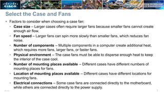
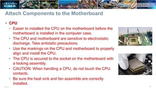
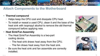
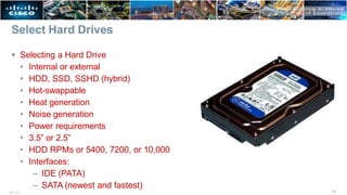
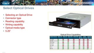
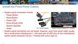
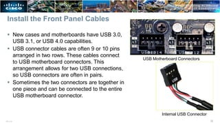
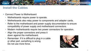
Chapter 2: PC
Assembly
1
ITE v7.0
IT Essentials v7.0
Chapter 2 - Sections & Objectives
2
ITE v7.0
 2.1 Assemble the Computer
• Build a computer.
– Define general and fire safety standards.
– Connect the power supply.
– Install the motherboard components.
– Install internal drives.
– Install the adapter cards.
– Identify additional storage.
– Connect computer components with appropriate cables.
2.1 ASSEMBLE THE COMPUTER
3
ITE v7.0
Personal, Equipment, and Fire Safety
4
ITE v7.0
 Personal, equipment, and fire safety precautions while working in a computer:
• Remove watches, jewelry, and loose clothing
• Turn off and unplug equipment
• Remove clutter from workspace
• Proper lifting procedures
• Cover sharp edges inside the computer
• Wear safety goggles
• ESD safety and proper use
• Fire extinguisher availability, rating, and use (P-A-S-S)
• First Aide availability and use
• Component storage and handling
Select the Case and Fans
vents in the system case to facilitate positive air flow.
5
ITE v7.0
• Model Type – The motherboard determines the type of case you can use. The
size and shape must match.
• Size – A computer with many components will need more room for airflow to
keep the system cool.
• Power Supply – Match the power supply rating and connection type to the
motherboard.
• Appearance – There are many case designs to choose from.
• Status Display – LEDs mounted on outside of case tell you if the system has
power, when the hard drive is in use, and when the computer is in sleep or
hibernate mode.
• Vents/Fans – All cases have a vent for the power supply, and some have extra
ITE v7.0 6
Select a Power Supply
 Factors to consider when choosing a power supply
• Type of Motherboard – The power supply must be compatible with the
motherboard.
• Required Wattage – Add the wattage for each component. If the wattage is not
listed on a component, calculate it by multiplying its voltage and amperage. If
the component requires different levels of wattage, use the higher requirement.
• Number of components – Make sure the power supply provides enough
wattage to support the number and types of components plus another 20% at a
minimum.
• Type of components – Make sure the power supply provides the right types of
power connectors.
• Type of case – Make sure the power supply can be mounted in the desired
case.
Select the Case and Fans
7
ITE v7.0
 Factors to consider when choosing a case fan:
• Case size – Larger cases often require larger fans because smaller fans cannot create
enough air flow.
• Fan speed – Larger fans can spin more slowly than smaller fans, which reduces fan
noise.
• Number of components – Multiple components in a computer create additional heat,
which requires more fans, larger fans, or faster fans.
• Physical environment – The case fans must be able to disperse enough heat to keep
the interior of the case cool.
• Number of mounting places available – Different cases have different numbers of
mounting places for fans.
• Location of mounting places available – Different cases have different locations for
mounting fans.
• Electrical connections – Some case fans are connected directly to the motherboard,
while others are connected directly to the power supply.
Open the Case and Connect the Power Supply
 Install the Power Supply
• Modern cases include a specific area for the power supply.
• Consult the case and power supply’s manuals
for more information.
• Align the holes in the power supply with the holes in the case.
• Secure the power supply to the case using
the proper screws.
• Make sure that all the screws are in place and tightened
correctly.
• Use a cable tie to secure all the cables out of the way.
• A modular power supply will help eliminate cable clutter
within a computer case.
8
ITE v7.0
Select the Motherboard
 Factors to consider when choosing a motherboard:
• CPU socket type and speed
• RAM type and amount
• Front-side Bus speed
• Capabilities
– Chipset
– Expansion slots
– I/O ports
– Built-in ports
9
ITE v7.0
Select a Replacement Motherboard
 When selecting a replacement motherboard,
make sure that it supports or accommodates:
• CPU
• RAM
• Video adapter, other adapter cards
• Socket and chipset on motherboard are
compatible with the CPU.
• The existing heat sink and fan assembly when reusing the CPU .
• The number/type of expansion slots. They must match the existing adapter
cards and allow for new cards.
• The existing power supply connections must fit the new motherboard.
• New motherboard must fit into the current computer case.
10
ITE v7.0
CPU Socket Types
 Land Grid Array (LGA)
• Most common type of CPU today
• Pins are in the socket and receptacles on the CPU
• Allows for a higher pin density
• Inserted into a Zero Insertion Force (ZIF) socket
mounted on the motherboard
 Pin Grid Array (PGA)
• Pins are on the CPU and receptacles in the socket
 Ball Grid Array (BGA)
• CPU is soldered to the motherboard
• Usually found in laptops, phones, and tablets
11
ITE v7.0
Select the CPU and CPU Cooling
 Selecting the CPU
• Socket type
• Speed
• Capabilities
 Selecting a Heat Sink
• Physical specifications – Must match the socket type
and not interfere with any other components attached
to the motherboard.
• Case size – Must fit within the case.
• Physical environment – Must be able to disperse
enough heat to keep the CPU cool.
• Active or Passive
12
ITE v7.0
Types of RAM
13
ITE v7.0
 DRAM
• Dynamic Random Access Memory
• Uses capacitors that need constant power to keep them from fading
• This process of charging is called Refresh
• Most DRAM needs to be refreshed every 2 ms
• Small and affordable, but slower than SRAM
 SRAM
• Static Random Access Memory
• Uses transistors
• Large and expensive, but fast
• Commonly used as cache
Types of RAM
 DIP (Dual Inline Pin)
• Small amount of memory (>1MB)
 SIPP (Single Inline Pin Package)
• Extinct because the pins were easy to bend and break
 SIMM (Single Inline Memory Module)
• Two different styles – 30 pin and 72 pin
 DIMM (Dual Inline Memory Module)
• 168 pins long (84 contacts per side)
• Also called SDRAM (Synchronous DRAM)
• Runs at the same speed as the FSB
• 64 bit data bus
• +3.3v
DIP
SIPP
30-pin SIMM
72-pin SIMM
168-pin DIMM or SDRAM
14
ITE v7.0
Types of RAM
 DDR-SDRAM (Double Data Rate Synchronous DRAM)
• Twice as fast as SDRAM (if used in dual channel
configuration)
• Will not interchange with SDRAM
• 64 bit data bus
 DDR2
 DDR3
 DDR4
 DDR5
 SODIMM (Small Outline DIMM)
• Found in laptops and notebooks
15
ITE v7.0
Select the RAM
 The RAM must be compatible with the motherboard.
 The speed of the RAM must be supported by the chipset.
 New RAM may be needed when an application locks up or the computer displays
frequent error messages. To determine if the problem is the RAM, execute the
RAM test in the BIOS.
 Memory may also be categorized as unbuffered or buffered:
• Unbuffered memory – This is regular memory for computers. The computer
reads data directly from the memory banks making it faster than buffered
memory.
• Buffered memory – Specialized memory for servers
and high-end workstations that use a large amount of
RAM. These have a control chip built into the module
that assists the memory controller in managing large quantities of RAM.
16
ITE v7.0
Attach Components to the Motherboard
 CPU
• Easier to installed the CPU on the motherboard before the
motherboard is installed in the computer case.
• The CPU and motherboard are sensitive to electrostatic
discharge. Take antistatic precautions.
• Use the markings on the CPU and motherboard to properly
align and install the CPU.
• The CPU is secured to the socket on the motherboard with
a locking assembly.
• CAUTION: When handling a CPU, do not touch the CPU
contacts.
• Be sure the heat sink and fan assemble are correctly
installed.
17
ITE v7.0
Attach Components to the Motherboard
 Thermal compound
• Helps keep the CPU cool and dissipate CPU heat.
• To install or reseat a used CPU, clean it and the base of the
heat sink with isopropyl alcohol to remove the old thermal
compound before applying new.
 Heat Sink/Fan Assembly
• The Heat Sink/Fan Assembly is a two-part
cooling device.
– The heat sink draws heat away from the CPU.
– The fan draws heat away from the heat sink.
• Be sure the heat sink and fan assemble are correctly
installed.
18
ITE v7.0
Attach Components to the Motherboard
 RAM
• Easier to installed RAM on the motherboard
before the motherboard is installed in the
computer case.
• RAM is highly sensitive to ESD.
• RAM is designed to install in one specific direction. The notch in the memory
module should be aligned with a notch in the memory slot.
• Make sure to check the markings before applying pressure.
• Use the documentation provided with the motherboard and RAM for more
information on RAM installation.
19
ITE v7.0
Install the Motherboard
 Install the Motherboard
• When the CPU, heat sink, fan and RAM are installed on the motherboard, the
motherboard can be installed in the case.
• Plastic and metal standoffs are used to mount the motherboard at the correct
height, to prevent it from touching the metal portions of the case and ground the
motherboard to the case.
• The I/O connectors on the back of the motherboard
should be aligned with the openings in the I/O plate.
The I/O connector plate or Backplane makes the I/O
ports of the motherboard available for connection in a
variety of computer cases.
20
ITE v7.0
Select Hard Drives
 Selecting a Hard Drive
• Internal or external
• HDD, SSD, SSHD (hybrid)
• Hot-swappable
• Heat generation
• Noise generation
• Power requirements
• 3.5” or 2.5”
• HDD RPMs or 5400, 7200, or 10,000
• Interfaces:
– IDE (PATA)
– SATA (newest and fastest)
21
ITE v7.0
Select Optical Drives
 Selecting an Optical Drive
 Connector type
 Reading capability
 Writing capability
 Optical media type
 5.25”
Optical Drive Capabilities
22
ITE v7.0
Install the Hard Drive
 Install the Internal Drive
• Internal drives are installed in
empty hard drive bays found in
the case.
• The empty bay must match the
drive’s size.
• Leave some space between
the drives when installing
multiple drives.
• The drive’s metal plate should
face up to allow better heat
dissipation.
23
ITE v7.0
Install the Optical Drive
 Step 1. From the front of the case, choose the drive bay
that you want to hold the drive. Remove the faceplate
from that bay if necessary.
 Step 2: Position the optical drive so that it aligns with the
5.25 inch (13.34 cm.) drive bay opening at the front of
the case, as shown in the figure.
 Step 3. Insert the optical drive into the drive bay so that
the optical drive screw holes align with the screw holes
in the case.
 Step 4. Secure the optical drive to the case using the
proper screws.
 Installation Tip: Slightly hand-tighten all the screws
before tightening any of them with a screw driver. This
will make it easier to tighten the last two screws.
24
ITE v7.0
Motherboard Expansion Slots
 Common Expansion slots found on a motherboard:
• AGP – Accelerated Graphic Port
– Has 1x, 2x, 4x, 8x speeds
• PCI – Peripheral Component Interconnect
– Can connect up to five external components
– Uses a parallel expansion bus
• PCIe – PCI Express
– Has 1x, 4x, 8x, 16x slots
– Each type is a different length
– Has the highest transfer speed of any expansion slot
– Sends data one bit at a time over a serial bus
25
ITE v7.0
Other Factors for Adapter Card Selection
 Adapter cards are designed for a specific task and add extra functionality to a computer.
There are a variety of adapter cards:
• Graphics/Video
• Sound
• Storage Controller
• I/O
• NIC
• Capture
 Before purchasing an adapter card, consider the following questions:
• What are the user’s current and future needs?
• Is there an open and compatible expansion slot available?
• What are the possible configuration options?
26
ITE v7.0
Install the Adapter Cards
 Expansion cards are installed into an
appropriate slot on the motherboard.
• Installation Tip: Research the length of the
video card. Longer cards may not be
compatible with certain motherboards. Some
adapter cards may come with mounting
brackets of different heights to accommodate
these cases.
• Installation Tip: Some cases have small slots
at the bottom of the hole where the cover was
removed. Slide the bottom of the mounting
bracket into this slot before seating the card.
27
ITE v7.0
Select a Media Reader
 Several media card formats have been developed over the years including:
• Secure digital (SD
• MicroSD
• MiniSD
• CompactFlash
• Memory Stick
 Choose a media reader based on current and
future needs:
• Media cards supported
• Internal or external
• Media size
• Connector type
28
ITE v7.0
Select External Storage
 External USB flash drives, sometimes called thumb drives, are commonly used as
removable external storage. External storage devices connect to an external port
using USB, eSATA, or Thunderbolt ports.
 Choose the correct type of external storage for your customer’s needs. For
example, if your customer needs to
transfer a small amount of data, such as
a single presentation, an external flash
drive is a good choice. If your customer
needs to back up or transfer large
amounts of data, choose an external
hard drive.
29
ITE v7.0
Install the Front Panel Cables
 A computer case typically
has a power button and
visible activity lights on the
front of the case. The case
will include front panel
cables that must be
connected to a common
system panel connector on
a motherboard. Writing on
the motherboard near the
system panel connector
shows where each cable is
connected.
Front Panel Connectors
System Panel Connector
30
ITE v7.0
Install the Front Panel Cables
 System panel connectors include:
• Power Button
• Reset Button
• Power LED
• Drive Activity LEDs
• System Speaker
• Audio
 System panel connectors are not keyed. However, each front panel cable usually
has a small arrow indicating pin 1, and each pair of LED pins on the motherboard
system panel connector has pin 1 marked with a plus sign (+).
Pin 1 Arrow Indicator System Panel Connector Pin 1 Indicator
31
ITE v7.0
Install the Front Panel Cables
 New cases and motherboards have USB 3.0,
USB 3.1, or USB 4.0 capabilities.
 USB connector cables are often 9 or 10 pins
arranged in two rows. These cables connect
to USB motherboard connectors. This
arrangement allows for two USB connections,
so USB connectors are often in pairs.
 Sometimes the two connectors are together in
one piece and can be connected to the entire
USB motherboard connector.
USB Motherboard Connectors
Internal USB Connector
32
ITE v7.0
Install the Front Panel Cables
33
ITE v7.0
 Power Button – Align pin 1 of the two-pin front panel power button cable with the power
button pins on the motherboard.
 Reset Button – Align pin 1 of the two-pin front panel reset button cable with the reset button
pins on the motherboard.
 Power LED – Align pin 1 of the front panel power LED cable with the
power LED pins on the motherboard.
 Drive Activity LED – Align pin 1 of the front panel drive activity cable with the drive activity
pins on the motherboard.
 System Speaker – Align pin 1 of the front panel system speaker cable with
the system speaker pins on the motherboard.
 Audio Cables – Due to the specialized function and variety of the hardware, consult the
motherboard, case, and audio panel documentation for specific instructions.
 USB – Align pin 1 of the USB cable with the USB pins on the motherboard.
Connect Internal Cables
 Power cables are used to distribute electricity from the power supply to the
motherboard and other components.
 PCIe may take an additional 6 or 8-pin power connector.
 High-end video cards may take up to 2 8-pin power connectors.
ATX
AUX Berg
SATA Molex
34
ITE v7.0
Install the Cables
 Connect Power to Motherboard
• Motherboards require power to operate.
• Motherboards also relay power to components and adapter cards.
• Refer to the motherboard and power supply documentation to ensure
compatibility of power supply and motherboard connectors.
• Modern motherboards require two power connectors for operation.
• Align the proper connectors and press it
down against the motherboard.
• Remember: If it is difficult to plug in a cable
or other part, something is wrong.
Do not use more force.
35
ITE v7.0
Install the Cables
 Connect Power to the Internal Drive and Case Fans
• Some drives accept different power connectors for compatibility.
• 4-pin Molex and 15-pin SATA are common hard drive connectors.
• Align the proper connectors and gently press it against the other end.
• Fans also need power and use 3-pin or 4-pin connectors.
36
ITE v7.0
Connect Internal Cables
37
ITE v7.0
 Data cables transmit data between the motherboard and storage devices, such
as hard drives. Some of examples of this type of cables are:
• PATA cable (40-pin IDE or EIDE)
• SATA cable (7-pin)
• Floppy drive data cable (34-pin)
 Connect the Internal Data Cables
• The internal and optical drives typically connect to the motherboard through
SATA cables.
• SATA are keyed to fit in only one direction. They also have locking tabs.
• Locate the SATA socket on the motherboard, align the connector and press it
gently to connect.
2.2 CHAPTER SUMMARY
38
ITE v7.0
Chapter 2: PC Assembly
39
ITE v7.0
 Build a computer.
• Define general and fire safety standards.
• Connect the power supply.
• Install the motherboard components.
• Install internal drives.
• Install the adapter cards.
• Identify additional storage.
• Connect computer components with appropriate cables.
41
ITE v7.0

ITE7Ch2.pptx

  • 1.
    Chapter 2: PC Assembly 1 ITEv7.0 IT Essentials v7.0
  • 2.
    Chapter 2 -Sections & Objectives 2 ITE v7.0  2.1 Assemble the Computer • Build a computer. – Define general and fire safety standards. – Connect the power supply. – Install the motherboard components. – Install internal drives. – Install the adapter cards. – Identify additional storage. – Connect computer components with appropriate cables.
  • 3.
    2.1 ASSEMBLE THECOMPUTER 3 ITE v7.0
  • 4.
    Personal, Equipment, andFire Safety 4 ITE v7.0  Personal, equipment, and fire safety precautions while working in a computer: • Remove watches, jewelry, and loose clothing • Turn off and unplug equipment • Remove clutter from workspace • Proper lifting procedures • Cover sharp edges inside the computer • Wear safety goggles • ESD safety and proper use • Fire extinguisher availability, rating, and use (P-A-S-S) • First Aide availability and use • Component storage and handling
  • 5.
    Select the Caseand Fans vents in the system case to facilitate positive air flow. 5 ITE v7.0 • Model Type – The motherboard determines the type of case you can use. The size and shape must match. • Size – A computer with many components will need more room for airflow to keep the system cool. • Power Supply – Match the power supply rating and connection type to the motherboard. • Appearance – There are many case designs to choose from. • Status Display – LEDs mounted on outside of case tell you if the system has power, when the hard drive is in use, and when the computer is in sleep or hibernate mode. • Vents/Fans – All cases have a vent for the power supply, and some have extra
  • 6.
    ITE v7.0 6 Selecta Power Supply  Factors to consider when choosing a power supply • Type of Motherboard – The power supply must be compatible with the motherboard. • Required Wattage – Add the wattage for each component. If the wattage is not listed on a component, calculate it by multiplying its voltage and amperage. If the component requires different levels of wattage, use the higher requirement. • Number of components – Make sure the power supply provides enough wattage to support the number and types of components plus another 20% at a minimum. • Type of components – Make sure the power supply provides the right types of power connectors. • Type of case – Make sure the power supply can be mounted in the desired case.
  • 7.
    Select the Caseand Fans 7 ITE v7.0  Factors to consider when choosing a case fan: • Case size – Larger cases often require larger fans because smaller fans cannot create enough air flow. • Fan speed – Larger fans can spin more slowly than smaller fans, which reduces fan noise. • Number of components – Multiple components in a computer create additional heat, which requires more fans, larger fans, or faster fans. • Physical environment – The case fans must be able to disperse enough heat to keep the interior of the case cool. • Number of mounting places available – Different cases have different numbers of mounting places for fans. • Location of mounting places available – Different cases have different locations for mounting fans. • Electrical connections – Some case fans are connected directly to the motherboard, while others are connected directly to the power supply.
  • 8.
    Open the Caseand Connect the Power Supply  Install the Power Supply • Modern cases include a specific area for the power supply. • Consult the case and power supply’s manuals for more information. • Align the holes in the power supply with the holes in the case. • Secure the power supply to the case using the proper screws. • Make sure that all the screws are in place and tightened correctly. • Use a cable tie to secure all the cables out of the way. • A modular power supply will help eliminate cable clutter within a computer case. 8 ITE v7.0
  • 9.
    Select the Motherboard Factors to consider when choosing a motherboard: • CPU socket type and speed • RAM type and amount • Front-side Bus speed • Capabilities – Chipset – Expansion slots – I/O ports – Built-in ports 9 ITE v7.0
  • 10.
    Select a ReplacementMotherboard  When selecting a replacement motherboard, make sure that it supports or accommodates: • CPU • RAM • Video adapter, other adapter cards • Socket and chipset on motherboard are compatible with the CPU. • The existing heat sink and fan assembly when reusing the CPU . • The number/type of expansion slots. They must match the existing adapter cards and allow for new cards. • The existing power supply connections must fit the new motherboard. • New motherboard must fit into the current computer case. 10 ITE v7.0
  • 11.
    CPU Socket Types Land Grid Array (LGA) • Most common type of CPU today • Pins are in the socket and receptacles on the CPU • Allows for a higher pin density • Inserted into a Zero Insertion Force (ZIF) socket mounted on the motherboard  Pin Grid Array (PGA) • Pins are on the CPU and receptacles in the socket  Ball Grid Array (BGA) • CPU is soldered to the motherboard • Usually found in laptops, phones, and tablets 11 ITE v7.0
  • 12.
    Select the CPUand CPU Cooling  Selecting the CPU • Socket type • Speed • Capabilities  Selecting a Heat Sink • Physical specifications – Must match the socket type and not interfere with any other components attached to the motherboard. • Case size – Must fit within the case. • Physical environment – Must be able to disperse enough heat to keep the CPU cool. • Active or Passive 12 ITE v7.0
  • 13.
    Types of RAM 13 ITEv7.0  DRAM • Dynamic Random Access Memory • Uses capacitors that need constant power to keep them from fading • This process of charging is called Refresh • Most DRAM needs to be refreshed every 2 ms • Small and affordable, but slower than SRAM  SRAM • Static Random Access Memory • Uses transistors • Large and expensive, but fast • Commonly used as cache
  • 14.
    Types of RAM DIP (Dual Inline Pin) • Small amount of memory (>1MB)  SIPP (Single Inline Pin Package) • Extinct because the pins were easy to bend and break  SIMM (Single Inline Memory Module) • Two different styles – 30 pin and 72 pin  DIMM (Dual Inline Memory Module) • 168 pins long (84 contacts per side) • Also called SDRAM (Synchronous DRAM) • Runs at the same speed as the FSB • 64 bit data bus • +3.3v DIP SIPP 30-pin SIMM 72-pin SIMM 168-pin DIMM or SDRAM 14 ITE v7.0
  • 15.
    Types of RAM DDR-SDRAM (Double Data Rate Synchronous DRAM) • Twice as fast as SDRAM (if used in dual channel configuration) • Will not interchange with SDRAM • 64 bit data bus  DDR2  DDR3  DDR4  DDR5  SODIMM (Small Outline DIMM) • Found in laptops and notebooks 15 ITE v7.0
  • 16.
    Select the RAM The RAM must be compatible with the motherboard.  The speed of the RAM must be supported by the chipset.  New RAM may be needed when an application locks up or the computer displays frequent error messages. To determine if the problem is the RAM, execute the RAM test in the BIOS.  Memory may also be categorized as unbuffered or buffered: • Unbuffered memory – This is regular memory for computers. The computer reads data directly from the memory banks making it faster than buffered memory. • Buffered memory – Specialized memory for servers and high-end workstations that use a large amount of RAM. These have a control chip built into the module that assists the memory controller in managing large quantities of RAM. 16 ITE v7.0
  • 17.
    Attach Components tothe Motherboard  CPU • Easier to installed the CPU on the motherboard before the motherboard is installed in the computer case. • The CPU and motherboard are sensitive to electrostatic discharge. Take antistatic precautions. • Use the markings on the CPU and motherboard to properly align and install the CPU. • The CPU is secured to the socket on the motherboard with a locking assembly. • CAUTION: When handling a CPU, do not touch the CPU contacts. • Be sure the heat sink and fan assemble are correctly installed. 17 ITE v7.0
  • 18.
    Attach Components tothe Motherboard  Thermal compound • Helps keep the CPU cool and dissipate CPU heat. • To install or reseat a used CPU, clean it and the base of the heat sink with isopropyl alcohol to remove the old thermal compound before applying new.  Heat Sink/Fan Assembly • The Heat Sink/Fan Assembly is a two-part cooling device. – The heat sink draws heat away from the CPU. – The fan draws heat away from the heat sink. • Be sure the heat sink and fan assemble are correctly installed. 18 ITE v7.0
  • 19.
    Attach Components tothe Motherboard  RAM • Easier to installed RAM on the motherboard before the motherboard is installed in the computer case. • RAM is highly sensitive to ESD. • RAM is designed to install in one specific direction. The notch in the memory module should be aligned with a notch in the memory slot. • Make sure to check the markings before applying pressure. • Use the documentation provided with the motherboard and RAM for more information on RAM installation. 19 ITE v7.0
  • 20.
    Install the Motherboard Install the Motherboard • When the CPU, heat sink, fan and RAM are installed on the motherboard, the motherboard can be installed in the case. • Plastic and metal standoffs are used to mount the motherboard at the correct height, to prevent it from touching the metal portions of the case and ground the motherboard to the case. • The I/O connectors on the back of the motherboard should be aligned with the openings in the I/O plate. The I/O connector plate or Backplane makes the I/O ports of the motherboard available for connection in a variety of computer cases. 20 ITE v7.0
  • 21.
    Select Hard Drives Selecting a Hard Drive • Internal or external • HDD, SSD, SSHD (hybrid) • Hot-swappable • Heat generation • Noise generation • Power requirements • 3.5” or 2.5” • HDD RPMs or 5400, 7200, or 10,000 • Interfaces: – IDE (PATA) – SATA (newest and fastest) 21 ITE v7.0
  • 22.
    Select Optical Drives Selecting an Optical Drive  Connector type  Reading capability  Writing capability  Optical media type  5.25” Optical Drive Capabilities 22 ITE v7.0
  • 23.
    Install the HardDrive  Install the Internal Drive • Internal drives are installed in empty hard drive bays found in the case. • The empty bay must match the drive’s size. • Leave some space between the drives when installing multiple drives. • The drive’s metal plate should face up to allow better heat dissipation. 23 ITE v7.0
  • 24.
    Install the OpticalDrive  Step 1. From the front of the case, choose the drive bay that you want to hold the drive. Remove the faceplate from that bay if necessary.  Step 2: Position the optical drive so that it aligns with the 5.25 inch (13.34 cm.) drive bay opening at the front of the case, as shown in the figure.  Step 3. Insert the optical drive into the drive bay so that the optical drive screw holes align with the screw holes in the case.  Step 4. Secure the optical drive to the case using the proper screws.  Installation Tip: Slightly hand-tighten all the screws before tightening any of them with a screw driver. This will make it easier to tighten the last two screws. 24 ITE v7.0
  • 25.
    Motherboard Expansion Slots Common Expansion slots found on a motherboard: • AGP – Accelerated Graphic Port – Has 1x, 2x, 4x, 8x speeds • PCI – Peripheral Component Interconnect – Can connect up to five external components – Uses a parallel expansion bus • PCIe – PCI Express – Has 1x, 4x, 8x, 16x slots – Each type is a different length – Has the highest transfer speed of any expansion slot – Sends data one bit at a time over a serial bus 25 ITE v7.0
  • 26.
    Other Factors forAdapter Card Selection  Adapter cards are designed for a specific task and add extra functionality to a computer. There are a variety of adapter cards: • Graphics/Video • Sound • Storage Controller • I/O • NIC • Capture  Before purchasing an adapter card, consider the following questions: • What are the user’s current and future needs? • Is there an open and compatible expansion slot available? • What are the possible configuration options? 26 ITE v7.0
  • 27.
    Install the AdapterCards  Expansion cards are installed into an appropriate slot on the motherboard. • Installation Tip: Research the length of the video card. Longer cards may not be compatible with certain motherboards. Some adapter cards may come with mounting brackets of different heights to accommodate these cases. • Installation Tip: Some cases have small slots at the bottom of the hole where the cover was removed. Slide the bottom of the mounting bracket into this slot before seating the card. 27 ITE v7.0
  • 28.
    Select a MediaReader  Several media card formats have been developed over the years including: • Secure digital (SD • MicroSD • MiniSD • CompactFlash • Memory Stick  Choose a media reader based on current and future needs: • Media cards supported • Internal or external • Media size • Connector type 28 ITE v7.0
  • 29.
    Select External Storage External USB flash drives, sometimes called thumb drives, are commonly used as removable external storage. External storage devices connect to an external port using USB, eSATA, or Thunderbolt ports.  Choose the correct type of external storage for your customer’s needs. For example, if your customer needs to transfer a small amount of data, such as a single presentation, an external flash drive is a good choice. If your customer needs to back up or transfer large amounts of data, choose an external hard drive. 29 ITE v7.0
  • 30.
    Install the FrontPanel Cables  A computer case typically has a power button and visible activity lights on the front of the case. The case will include front panel cables that must be connected to a common system panel connector on a motherboard. Writing on the motherboard near the system panel connector shows where each cable is connected. Front Panel Connectors System Panel Connector 30 ITE v7.0
  • 31.
    Install the FrontPanel Cables  System panel connectors include: • Power Button • Reset Button • Power LED • Drive Activity LEDs • System Speaker • Audio  System panel connectors are not keyed. However, each front panel cable usually has a small arrow indicating pin 1, and each pair of LED pins on the motherboard system panel connector has pin 1 marked with a plus sign (+). Pin 1 Arrow Indicator System Panel Connector Pin 1 Indicator 31 ITE v7.0
  • 32.
    Install the FrontPanel Cables  New cases and motherboards have USB 3.0, USB 3.1, or USB 4.0 capabilities.  USB connector cables are often 9 or 10 pins arranged in two rows. These cables connect to USB motherboard connectors. This arrangement allows for two USB connections, so USB connectors are often in pairs.  Sometimes the two connectors are together in one piece and can be connected to the entire USB motherboard connector. USB Motherboard Connectors Internal USB Connector 32 ITE v7.0
  • 33.
    Install the FrontPanel Cables 33 ITE v7.0  Power Button – Align pin 1 of the two-pin front panel power button cable with the power button pins on the motherboard.  Reset Button – Align pin 1 of the two-pin front panel reset button cable with the reset button pins on the motherboard.  Power LED – Align pin 1 of the front panel power LED cable with the power LED pins on the motherboard.  Drive Activity LED – Align pin 1 of the front panel drive activity cable with the drive activity pins on the motherboard.  System Speaker – Align pin 1 of the front panel system speaker cable with the system speaker pins on the motherboard.  Audio Cables – Due to the specialized function and variety of the hardware, consult the motherboard, case, and audio panel documentation for specific instructions.  USB – Align pin 1 of the USB cable with the USB pins on the motherboard.
  • 34.
    Connect Internal Cables Power cables are used to distribute electricity from the power supply to the motherboard and other components.  PCIe may take an additional 6 or 8-pin power connector.  High-end video cards may take up to 2 8-pin power connectors. ATX AUX Berg SATA Molex 34 ITE v7.0
  • 35.
    Install the Cables Connect Power to Motherboard • Motherboards require power to operate. • Motherboards also relay power to components and adapter cards. • Refer to the motherboard and power supply documentation to ensure compatibility of power supply and motherboard connectors. • Modern motherboards require two power connectors for operation. • Align the proper connectors and press it down against the motherboard. • Remember: If it is difficult to plug in a cable or other part, something is wrong. Do not use more force. 35 ITE v7.0
  • 36.
    Install the Cables Connect Power to the Internal Drive and Case Fans • Some drives accept different power connectors for compatibility. • 4-pin Molex and 15-pin SATA are common hard drive connectors. • Align the proper connectors and gently press it against the other end. • Fans also need power and use 3-pin or 4-pin connectors. 36 ITE v7.0
  • 37.
    Connect Internal Cables 37 ITEv7.0  Data cables transmit data between the motherboard and storage devices, such as hard drives. Some of examples of this type of cables are: • PATA cable (40-pin IDE or EIDE) • SATA cable (7-pin) • Floppy drive data cable (34-pin)  Connect the Internal Data Cables • The internal and optical drives typically connect to the motherboard through SATA cables. • SATA are keyed to fit in only one direction. They also have locking tabs. • Locate the SATA socket on the motherboard, align the connector and press it gently to connect.
  • 38.
  • 39.
    Chapter 2: PCAssembly 39 ITE v7.0  Build a computer. • Define general and fire safety standards. • Connect the power supply. • Install the motherboard components. • Install internal drives. • Install the adapter cards. • Identify additional storage. • Connect computer components with appropriate cables.
  • 40.