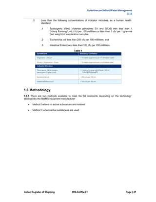
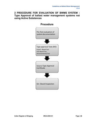
This document provides guidelines on ballast water management developed by the Indian Register of Shipping. It summarizes the International Convention for the Control and Management of Ship's Ballast Water and Sediments (BWM Convention) adopted by the International Maritime Organization in 2004 to regulate ballast water discharge. The guidelines explain ship requirements under the convention including ballast water management options, sediment management, and record keeping. It also covers compliance requirements and available ballast water treatment systems and technologies.


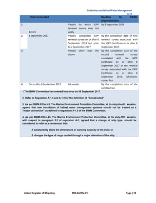

![Indian Register of Shipping IRS-G-ENV-01 Page | 16
Guidelines on Ballast Water Management
2018
Exclusive Economic Zone (EEZ), and are less than or equal to 1,600 gross register tons or
less than or equal to 3,000 gross tons.
non-seagoing vessels
vessels that take on and discharge ballast water exclusively in one COTP zone.
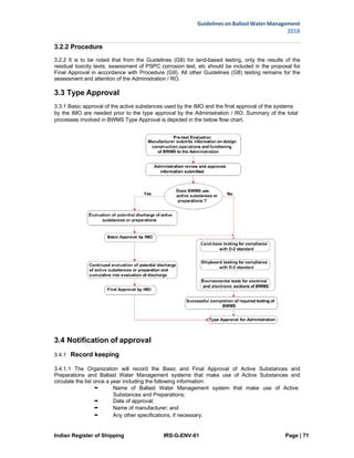
3.2.2.3 Extensions
3.2.2.3.1 If the options given by the USCG are not practicably available despite all efforts, vessel
owners can request an extension from the USCG to the implementation schedule. The availability of
an Alternate Management System (AMS) does not prohibit a vessel owner from receiving an
extension. The USCG regulations provide the process for requesting these extensions and when it
can be documented. Extension requests must be submitted to the Coast Guard no later than 12
months before the scheduled implementation date.
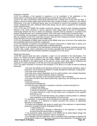
3.2.3 Ballast Water Treatment Standard
3.2.3.1 USCG treatment discharge standard is the same as the IMO BWM Convention D-2 Standard
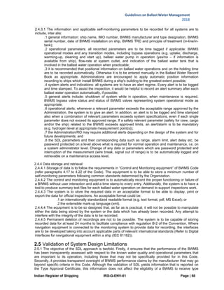
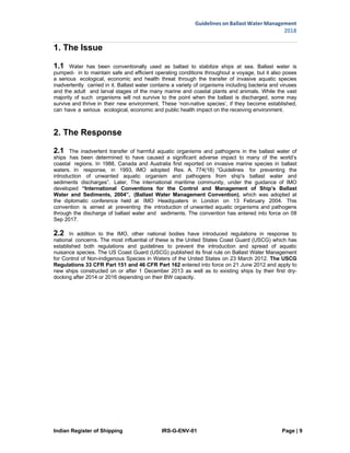
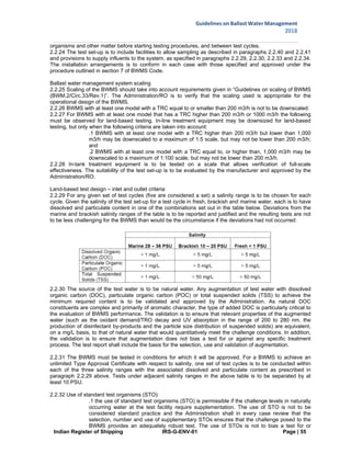
Table 3.2.2.1.1 Compliance Schedule for USCG Ballast Water Treatment Standard
Ballast Water
Capacity
Date Constructed Compliance Date
New
Vessels
All On or after 1 December,
2013
On Delivery
Existing
Vessels
Less than 1.500 [m3
]
Before 1 December, 2013
First scheduled dry docking
after 1 January, 2016
1.500 – 5.000 [m3
] First scheduled dry docking
after 1 January, 2014
Greater than 5.000 [m3
] First scheduled dry docking
after 1 January, 2016
3.2.4 Approval
3.2.4.1 The USCG requires that ballast water must be treated with a USCG type approved ballast
water treatment system.
3.2.4.2 In addition, to avoid penalizing ships that have already fitted a treatment system approved by
another flag administration, the USCG has introduced the Alternate Management System (AMS).
Some important features of the AMS are given below:
AMS are ballast water treatment systems which have been accepted for use in US waters by
the USCG
AMS is a temporary solution until the USCG type approved systems are available
AMS approval does not necessarily mean that the system will achieve the USCG type
approval
A ship with an AMS installed can only use this system for a period of five years beyond the
date when the ship would otherwise be required to comply with the USCG discharge standard
The list of AMS approved systems can be found through US Department of Homeland
Security’s website at https://homeport.usch.mil/ballast water
3.2.5 Port State Control
3.2.5.1 A report is required to be submitted to the USCG COTP 24 hours before arriving at a US port.
The ship must provide the COTP with access to the vessel in order to take samples of ballast water
and sediment; examine documents; and make other enquiries to assess compliance with USCG
requirements.](https://image.slidesharecdn.com/irs-g-env-01guidelines-on-bwm-210427025705/85/Irs-g-env-01-guidelines-on-bwm-16-320.jpg)


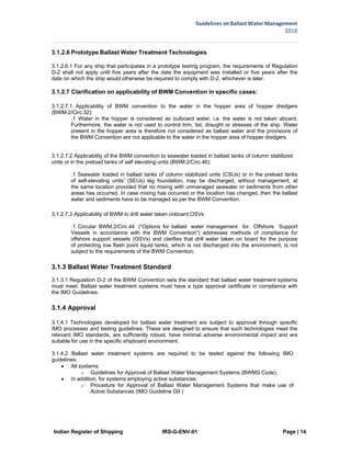
![Indian Register of Shipping IRS-G-ENV-01 Page | 59
Guidelines on Ballast Water Management
2018
be signed by:
[.1 the manufacturer or manufacturer's representative, if the inspection, tests or
evaluations are conducted by the manufacturer; or]
.2 the chief officer of the laboratory, or the chief officer's representative, if the
inspection or tests were conducted by an independent laboratory;
.13 appendices, including:
.1 the complete test plan and the data generated during tests and evaluations reported under
paragraph 2.57.8 above, including at least:
.1 for land-based tests, whether ambient, cultured or a mixture of test organisms
have been used (including a species-level identification for cultured organisms, and
an identification to the lowest possible taxonomic level for ambient organisms);
.2 for shipboard tests, the operating parameters of the system during successful
treatment operations (e.g. dosage rates, ultraviolet intensity and the energy
consumption of the BWMS under normal or tested TRC, if available);
.3 for SDL, details of all procedures, methods, data, models, results, explanations
and remarks, leading to validation; and
.4 invalid test information.
.2 the QMP, the QAPP and Quality Assurance and Quality Control records;
.3 maintenance logs including a record of any consumable components that were replaced;
and
.4 relevant records and test results maintained or created during testing.
2.2.58 The results of biological efficacy testing of the BWMS is to be accepted if during the land-based and
shipboard testing conducted as specified in sections "Shipboard tests" and "Land-based testing" of this
annex it is shown that the system has met the standard in regulation D-2 and that the uptake water quality
requirements were met in all individual test cycles as provided in paragraph 2.4.7 below.
2.2.59 The test report is to include all test cycles during land-based and shipboard tests, including failed test
cycles and invalid test cycles with the explanation required in paragraph 2.2.8.11.4 for both shipboard and
land-based tests.
2.2.60 The Administration shall identify and redact commercially sensitive information (information that is
proprietary and not related to the BWMS performance) and make all other information available to interested
parties and the Organization. The information is to include all of the test reports, including failed tests from
both land-based and shipboard testing.
2.3 Specification for environmental testing for approval of BWMS
2.3.1 The electrical and electronic sections of the BWMS in the standard production configuration are to be
subject to the relevant tests specified in paragraph 2.3.3 below at a laboratory approved for the purpose by
the Administration/RO or by the accreditation body of the laboratory, with relevant accreditation (as per
ISO/IEC 17025:2017) covering the relevant test standards.
2.3.2 Evidence of successful compliance with the environmental tests below is to be submitted to the
Administration/RO by the manufacturer together with the application for type approval.
2.3.3 Equipment is to be tested taking into account IACS UR E10, Rev.6.
2.3.4 A report on environmental tests is to be submitted to the Administration/RO and include at least the
information identified in paragraph 2.2.57 of this Annex.
2.4 Reporting
2.4.1 Introduction
2.4.1.1 BWMS is to monitor and store a minimum number of parameters for detailed evaluation. In addition,
all system indications and alerts are to be stored and available for inspection. Data storage and retrieval
are to follow common standards. This part gives an overview of the minimum required self-monitoring
parameters.
2.4.2 Monitoring of parameters
2.4.2.1 The applicable self-monitoring parameters listed below are to be recorded for every BWMS. Any
additional parameters that are necessary to ascertain system performance and safety are to be determined
by the Administration and stored in the system. If a parameter is not applicable due to the particulars of the
system, the Administration/RO may waive the requirement to record that parameter. Limiting operating
conditions on the operation of the BWMS are to be determined by the manufacturer and approved by the
Administration/RO.
2.4.3 General information for all systems](https://image.slidesharecdn.com/irs-g-env-01guidelines-on-bwm-210427025705/85/Irs-g-env-01-guidelines-on-bwm-59-320.jpg)