Download to read offline
![International Research Journal of Engineering and Technology (IRJET) e-ISSN: 2395-0056
Volume: 07 Issue: 04 | Apr 2020 www.irjet.net p-ISSN: 2395-0072
© 2020, IRJET | Impact Factor value: 7.34 | ISO 9001:2008 Certified Journal | Page 1572
High Frequency Tri-band Patch Antenna with Enhanced Bandwidth
Anjali K Netke1, V. V. Yerigeri2
1,2Department of Post Graduation, MBES COE Ambajogai (MS), India
1,2Dr. B. A. T. U. Lonere, India
2Professor & Head of Department, MBES COE, Ambajogai (MS), India
---------------------------------------------------------------------***----------------------------------------------------------------------
Abstract
We demonstrated and presented triple band line fed
microstrip patch antenna for wireless communication
application. In proposed design, we introduced F-shape
patch and ground plane of antenna, to enhance the
bandwidth of mictrostrip antenna. Adjusting the dimension
of ground plane and patch, its enhanced bandwidth at
primary and secondary resonance mode can increased
sufficiently to achieve desired bandwidth of proposed
antenna. We demonstrated many antenna structures to
study of these parameters on theresultingtriband response.
In this paper, we designed tripple-band microstrip rectangle
antenna with slot antenna using line-feed technique, it
support the three wireless communication bands that is
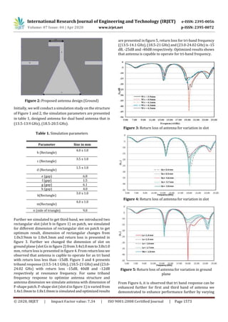
(12.9-14.3 GHz), (18.2-19.8 GHz) and (20.8-23.8 GHz).
Key Words: Trippleband Microstrip antenna, bandwidth
enhancement, Co-axial feed technique.
1. INTRODUCTION
With development of wireless communication and
microstrip antenna it has been found that, Microstrip
antenna analysis with different feed technique like co-axial,
line-feed technique etc, is good candidate t improveantenna
performance. Microstrip patch Antenna experimentally
optimize antenna parameters anddecreasestheReturnLoss
up to -35dB for the frequency range to operate forBluetooth
antenna in frequency range 2.4 GHz to 2.5GHz and VSWR is
less than 1.5 by using RT DUROID 5880[1]. In further study
of optimization of dual band microstrip antenna [2] it has
been found that the return loss for dual band Frequency at
2.4GHz is -43dB and at 3GHz is -27dB and acceptable VSWR.
To get compact size and maintain performance of antenna
for multiple band that is dual band, triple band antenna etc.,
various shapes of antenna was integrated [3]. It was
presented in [4], introducing slot into patch that is L-Shape,
experimentally increase bandwidth up to 13%. To enhance
bandwidth further various shapes like L-shape,U-shapeetc.,
slot was introduced andbandwidth upto42%wasincreased
[5,6]. In [7] and [8] the author’s proposed bandwidth
enhancement techniques that is by using photonic band gap
structure and wideband stacked microstrip antennas
respectively. By introducing stacked microstrip antenna
band width and gain was enhanced. While Designing of
symmetrical microstrip antenna, it has been found that
microstripantenna hasnarrowBandwidth [9],Asymmetrical
position of patch antenna on ground affect the performance
of antenna that is to enhance bandwidth it was also found
that asymmetrical position of slot on patch affects
performance of antenna[10] thatisasymmetrical L-shape,U-
shape position of slot on patch affects the performance. In
[10] designed asymmetrical slot of L-shaped on patch
antenna for UWB application with acceptable return loss
that is -10dB and peak gain 2.2 to 6.1 dBi for operating
bandwidth 3.01-11.30 GHz frequencies. In this paper we
simulated and presented our design by using HFSS.13
simulator. In this paper a line feed patch with two rectangle
slot microstrip antenna with two antisymmetrical notch
(Figure 1) is designed and simulated for thefrequencyrange
of 1-5 GHz. This antenna presents an extension to
Miniaturization of Differentially-Driven Microstrip Planar
Inverted F Antenna [11]. The proposed antenna hasa gainof
1.7 dBi.
2. PROPOSED DESIGN
The results of proposed triple band microstrip patch
antenna verified in HFSSSimulatorwithoptimization.Actual
patch shape is shown in figure 1,itconsistsofsymmetrical F-
shape structure on both side of dielectric substrate.Onpatch
side and ground side parasitic symmetrical rectangle are
introduced (as shown in figure 1 & 2). The resulting antenna
structure has the following parameters; the dielectric
substrate has length L = 18.4 mm, and its width W =13 mm,
dielectric constant and height of substrateareεr=4.4(FR-4)
and h= 1.0mm respectively.
Figure 1: Proposed antenna design (Patch)
(Online)](https://image.slidesharecdn.com/irjet-v7i4298-210203042713/85/IRJET-High-Frequency-Tri-Band-Patch-Antenna-with-Enhanced-Bandwidth-1-320.jpg)
![International Research Journal of Engineering and Technology (IRJET) e-ISSN: 2395-0056
Volume: 07 Issue: 04 | Apr 2020 www.irjet.net p-ISSN: 2395-0072
© 2020, IRJET | Impact Factor value: 7.34 | ISO 9001:2008 Certified Journal | Page 1572
High Frequency Tri-band Patch Antenna with Enhanced Bandwidth
Anjali K Netke1, V. V. Yerigeri2
1,2Department of Post Graduation, MBES COE Ambajogai (MS), India
1,2Dr. B. A. T. U. Lonere, India
2Professor & Head of Department, MBES COE, Ambajogai (MS), India
---------------------------------------------------------------------***----------------------------------------------------------------------
Abstract
We demonstrated and presented triple band line fed
microstrip patch antenna for wireless communication
application. In proposed design, we introduced F-shape
patch and ground plane of antenna, to enhance the
bandwidth of mictrostrip antenna. Adjusting the dimension
of ground plane and patch, its enhanced bandwidth at
primary and secondary resonance mode can increased
sufficiently to achieve desired bandwidth of proposed
antenna. We demonstrated many antenna structures to
study of these parameters on theresultingtriband response.
In this paper, we designed tripple-band microstrip rectangle
antenna with slot antenna using line-feed technique, it
support the three wireless communication bands that is
(12.9-14.3 GHz), (18.2-19.8 GHz) and (20.8-23.8 GHz).
Key Words: Trippleband Microstrip antenna, bandwidth
enhancement, Co-axial feed technique.
1. INTRODUCTION
With development of wireless communication and
microstrip antenna it has been found that, Microstrip
antenna analysis with different feed technique like co-axial,
line-feed technique etc, is good candidate t improveantenna
performance. Microstrip patch Antenna experimentally
optimize antenna parameters anddecreasestheReturnLoss
up to -35dB for the frequency range to operate forBluetooth
antenna in frequency range 2.4 GHz to 2.5GHz and VSWR is
less than 1.5 by using RT DUROID 5880[1]. In further study
of optimization of dual band microstrip antenna [2] it has
been found that the return loss for dual band Frequency at
2.4GHz is -43dB and at 3GHz is -27dB and acceptable VSWR.
To get compact size and maintain performance of antenna
for multiple band that is dual band, triple band antenna etc.,
various shapes of antenna was integrated [3]. It was
presented in [4], introducing slot into patch that is L-Shape,
experimentally increase bandwidth up to 13%. To enhance
bandwidth further various shapes like L-shape,U-shapeetc.,
slot was introduced andbandwidth upto42%wasincreased
[5,6]. In [7] and [8] the author’s proposed bandwidth
enhancement techniques that is by using photonic band gap
structure and wideband stacked microstrip antennas
respectively. By introducing stacked microstrip antenna
band width and gain was enhanced. While Designing of
symmetrical microstrip antenna, it has been found that
microstripantenna hasnarrowBandwidth [9],Asymmetrical
position of patch antenna on ground affect the performance
of antenna that is to enhance bandwidth it was also found
that asymmetrical position of slot on patch affects
performance of antenna[10] thatisasymmetrical L-shape,U-
shape position of slot on patch affects the performance. In
[10] designed asymmetrical slot of L-shaped on patch
antenna for UWB application with acceptable return loss
that is -10dB and peak gain 2.2 to 6.1 dBi for operating
bandwidth 3.01-11.30 GHz frequencies. In this paper we
simulated and presented our design by using HFSS.13
simulator. In this paper a line feed patch with two rectangle
slot microstrip antenna with two antisymmetrical notch
(Figure 1) is designed and simulated for thefrequencyrange
of 1-5 GHz. This antenna presents an extension to
Miniaturization of Differentially-Driven Microstrip Planar
Inverted F Antenna [11]. The proposed antenna hasa gainof
1.7 dBi.
2. PROPOSED DESIGN
The results of proposed triple band microstrip patch
antenna verified in HFSSSimulatorwithoptimization.Actual
patch shape is shown in figure 1,itconsistsofsymmetrical F-
shape structure on both side of dielectric substrate.Onpatch
side and ground side parasitic symmetrical rectangle are
introduced (as shown in figure 1 & 2). The resulting antenna
structure has the following parameters; the dielectric
substrate has length L = 18.4 mm, and its width W =13 mm,
dielectric constant and height of substrateareεr=4.4(FR-4)
and h= 1.0mm respectively.
Figure 1: Proposed antenna design (Patch)
(Online)](https://image.slidesharecdn.com/irjet-v7i4298-210203042713/75/IRJET-High-Frequency-Tri-Band-Patch-Antenna-with-Enhanced-Bandwidth-1-2048.jpg)
![International Research Journal of Engineering and Technology (IRJET) e-ISSN: 2395-0056
Volume: 07 Issue: 04 | Apr 2020 www.irjet.net p-ISSN: 2395-0072
© 2020, IRJET | Impact Factor value: 7.34 | ISO 9001:2008 Certified Journal | Page 1575
14.3 GHz, 18.2-19.8 GHz and 20.8-23.8 GHz. The proposed
antenna was been analyzed using a HFSS simulator.
REFERENCES
[1] Ahmed H. Reja “Study of Micro Strip Feed Line
PatchAntenna”, Antennas and Propagation International
Symposium, vol. 27, pp. 340-342 December 2008.
[2] Sahntanu Kumar Behera and Y. Choukiker, ”Design
andOptimization of Dual Band Micro Strip Antenna Using
Practicle Swarm Optimization Technique,” Springer Science
Business Media, LLC, pp. 1346-1354, 2010
[3] M. A. S. Alkanhal, ”Compact composite triple band
antenna”, Progress In Electromagnetics Research, PIER 93,
221-236, 2009
[4] A. A. Deshmukh and G. Kumar, “Compact broadband
gapcoupled shorted L-shaped microstrip antennas,” IEEE
Antennas and Propagation International Symposium, vol 1,
(Baltimore, Maryland), pp. 106–109, IEEE, July 2001.
[5] Z. M.Chen and Y. W. M. Chial, “Broadband probe-fed
Lshaped plate antenna,” Microwave and Optical Technology
Letters, vol. 26, pp. 204–206, 1985.
[6] K. F. Lee, K. M. Luk, K. F. Tong, Y. L. Yung, and T.Huynh,
“Experimental study of the rectangular patch with a U-
shaped slot,” IEEE Antennas and Propagation International
Symposium, vol.1, (Baltimore, Maryland), pp. 10–13, IEEE,
July 1996.
[7] S. C. Gao, L. W. Li, M. S. Leong, and T. S. Yeo, “Designand
analysis of a novel wideband microstrip antenna,” IEEE
Antennas and Propagation International Symposium,vol.1,
(Boston, Massachusetts), pp. 90–93, IEEE, July 2001.
[8] M. Khodier and C. Christodoulou, “A technique to
furtherincrease the bandwidth Of stacked microstrip
antennas,” IEEE Antennas and Propagation International
Symposium, vol. 3, pp. 1394–1397, IEEE, July 2000.
[9] Neenansha Jain, Anubhuti Khare, Rajesh Nema, “E-
ShapeMicro strip Patch Antenna on Different Thickness for
pervasive WirelessCommunication”,International Journal of
Advanced Computer Science and Applications, Vol. 2, No. 4,
2011
[10] K. Song, Y.-Z. Yin, S.-T. Fan, and B. Chen,” compact open
ended L-shaped slot antenna with asymmetrical rectangle
patch for UWB application”, Progress In Electromagnetics
Research C, Vol. 19, 235-243, 2011
[11]V.V.Reddy, N. V. S. N. Sarma, “Triband Circularly
Polarized Koch Fractal Boundary Microstrip Antenna”, IEEE
antennas and wireless propagation letters, vol. 13, 2014
[12] T.-H. Chang and J.-F. Kiang, “Compact multi-band H-
shaped slot antenna,”IEEE Trans. Antennas Propag., vol. 61,
no. 8, pp. 4345–4349,
[13] K. Song, Y.-Z. Yin, S.-T. Fan, and B. Chen, “compact open-
ended l-shaped slot antenna with asymmetrical rectangular
patch for UWB applications”, Progress In Electromagnetics
Research C, Vol. 19, 235-243, 2011
[14] Jianchun Xu et al, “A wide band F-shaped Microstrip
antenna”, IEEE Transactions On Antennas And Propagation
letter, 1536-1225 (c) 2016.
[15] W.-S. Chen and K.-L. Wong, “A coplanar waveguide-fed
printed slot antenna for dual-frequency operation,” in Proc.
IEEE AP-S Int. Symp., Jul. 2001, vol. 2, pp. 140–143.
[16] J.-S. Chen, “Triple-frequency annular-ring slot antennas
fed by CPW and microstrip line,” in Proc. IEEE AP-S Int.
Symp., vol. 2, pp. 557–560, Jun. 2003.
[17] J. H. Yoon and Y. C. Lee, “Modified bow-tie slot antenna
for the 2.4/5.2/5.8 GHz WLAN bands with a rectangular
tuning stub,” Microw. Opt. Technol. Lett., vol. 52, no. 1, pp.
126–130, Jan. 2011.
[18] HFSS10.0 User's Manual, Ansoft Corporation,
Pittsburgh.
AUTHOR’S PROFILE
Anjali Kashinath Netke,has completed
his Bachelor’s Degree from Electronics
and Telecommunication Department &
pursuing Masters in Digital
Communication Department in MBES
college of Engineering,Ambajogai,India
Prof. V. V. Yerigeri, has completed B.E
in Electronics & Communication
Engineering & M.E. in Power Electronics
& Perusing Ph. D in Signal Processing.He
has teaching experience of more than24
Years. He has presented many papers in
National & International Conferences &
Published more than 50 papers in National & International
Journals.](https://image.slidesharecdn.com/irjet-v7i4298-210203042713/85/IRJET-High-Frequency-Tri-Band-Patch-Antenna-with-Enhanced-Bandwidth-4-320.jpg)

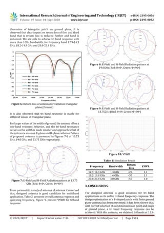
The document presents the design and simulation of a tri-band microstrip patch antenna. The antenna design uses an F-shaped patch with slots and a finite ground plane. Simulation results show the antenna operates in three bands: 12.9-14.3 GHz, 18.2-19.8 GHz, and 20.8-23.8 GHz with return losses less than -15 dB. Adjusting the dimensions of the slots and ground plane shapes allows tuning of the bandwidth and frequency response for multi-band operation. Radiation patterns are presented for key frequencies, demonstrating bi-directional patterns. The proposed antenna design achieves enhanced bandwidth for wireless applications.


![[IJCT-V3I2P20] Authors: Gidijala Sai Kumar,Gadiraju Mounika , Dusi Leela Ran...](https://cdn.slidesharecdn.com/ss_thumbnails/ijct-v3i2p20-160609061626-thumbnail.jpg?width=640&height=640&fit=bounds)


