Cheap Rate ➥8448380779 ▻Call Girls In Iffco Chowk Gurgaon
- Standard Specifications for Highway Bridges-American Association of State Highway and Transportation Officials (AASHTO) (2002).pdf
1. StandardSpecifications
for Highway Bridges
17th Edition-2002
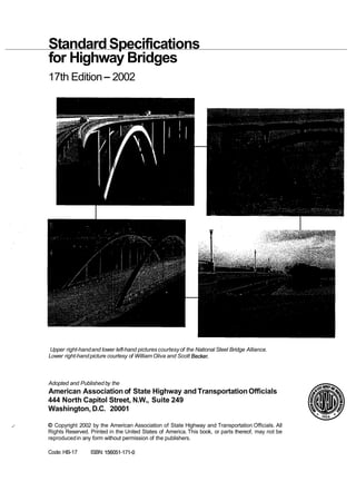
Upper right-handand lower left-hand pictures courtesyof the National Steel Bridge Alliance.
Lower right-handpicture courtesy of William Oliva and Scott Becker.
Adopted and Publishedby the
American Association of State Highway and TransportationOfficials
444 North Capitol Street, N.W., Suite 249
Washington, D.C. 20001
,
' O Copyright 2002 by the American Association of State Highway and Transportation Officials. All
Rights Reserved. Printed in the United States of America. This book, or parts thereof, may not be
reproducedin any form without permission of the publishers.
Code: HB-17 ISBN: 156051-171-0
2. AMERICAN ASSOCIATIONOF STATE HIGHWAY
A~+-NSPORfA'fION-OPPIC-I-A%S
EXECUTIVE COMMITTEE
2001-2002
VOTING MEMBERS
President: Brad Mallory,Pennsylvania
Vice President: James Codell,Kentucky
Secretary/Treasurer: Larry King, Pennsylvania
Regional Representatives:
Region I: Joseph Boardman, New York, One-YearTerm
James Weinstein,New Jersey, Two-Year Term
Region11: Bruce Saltsman,Tennessee, One-YearTerm
Fred Van Kirk, West Virginia,Two-Year Term
Region 111: Kirk Brown, Illinois,One-YearTerm
Henry Hungerbeeler,Missouri,Two-YearTerm
Region N: Joseph Perkins,Alaska, One-YearTerm
Tom Stephens, Nevada,Two-Year Tern
NON-VOTING MEMBERS
Immediate Past President: E. Dean Carlson, Kansas
Executive Director: John Horsley,Washington,D.C.
3. HIGHWAY SUBCOMMITTEE ON
BRIDGESAND STRUCTURES
2002
TOM LULAY, Oregon, Chaimzan
SANDRALARSON, Vice Chaimzan
JAMES D. COOPER,Federal Highway Administration, Secretary
ALABAMA,William F. Conway,George H.
Connor
ALASKA, Richard A. Pratt
ARIZONA, F. Daniel Davis
ARKANSAS, Phil Brand
CALIFORMA, Richard Land
COLORADO, MarkA. Leonard
CONNECTICUT,Gordon Barton
DELAWARE, Doug Finney, Dennis O'Shea
D.C., Donald Cooney
FLORIDA, William N. Nickas
GEORGIA, Paul Liles, Brian Swnmers
HAWAII,Paul Santo
IDAHO,Matthew M. Farrar
ILLINOIS,Ralph E. Anderson
INDIANA, Mary Jo Hamman
IOWA, Norman L. McDonald
KANSAS, Kenneth F. Hurst,Loren R. Risch
KENTUCKY,StephenE. Goodpaster
LOUISIANA, Hossein Ghara, Mark J. Momant
MAINE, James E. Tukey
MARYLAND, Earle S. Freedman
MASSACHUSETI'S, Alexander K. Bardow
MICHIGAN,Steve Beck
MINNESOTA, Dan Dorgan, Kevin Western
MISSISSIPPI,Harry LeeJames
MISSOURI, ShyamGupta
MONTANA,WilliamS. Fullerton
NEBRASKA,Lyman D. Freemon
NEVADA,William C. Crawford, Jr.
NEW HAMPSHIRE,Mark Richardson
NEW JERSEY,Harry A. Capers, Jr., Richard
W. Dunne
NEW MEXICO, Jimmy D. Camp
NEW YORK, James O'Comell, George
Christian
NORTH CAROLINA,Gregory R. Perfettie
NORTH DAKOTA, Terry Udland
OHIO, Timothy Keller
OKLAHOMA, Robert J. Rusch, Veldo Goins
OREGON,Mark E. Hirota
PENNSYLVANIA, R. Scott Christie
PUERTORICO, Jaime Cabre
RHODE ISLAND, Kazem Farhoumand
SOUTH CAROLINA, Randy R. Cannon, Jeff
Sizemore
SOUTH DAKOTA,John C. Cole
TENNESSEE,Edward P. Wasserman
TEXAS, Mary Lou Ralls
U.S. DOT, Nick E. Mpras
UTAH, David Nazare
VERMONT,James McCarthy
VIRGINIA, MalcolmT. Kerley
WASHINGTON,Jerry Weigel,Tony M. Allen
WESTVIRGINIA,James Sothen
WISCONSIN,StanleyW. Woods
WYOMING,Gregg C. Fredrick, Keith R.
Fulton
ALBERTA, Dilip K. Dasmohapatra
MANITOBA, IsmailElkholy
NORTHERN M A M A ISLANDS,John C.
Pangalinan
NEW BRUNSWICK,David Cogswell
NORTHAMPTON,R. T. Hughes
NORTHWESTTERRITORIES,John Bowen
NOVASCOTIA,Alan MacRae,Mark Pertus
ONTARIO, Vacant
SASKATCHEWAN, HervCBachelu
FHWA, ShoukryElnahal
MASS. METRO. DIST. COMM., David
Lenhardt
N.J. TURNPIKEAUTHORITY,Richard
Raczynski
NYSTATE BRIDGEAUTHORITY,William
Moreau
PORTAUTH. OF NYAND NJ, Joseph J.
Kelly, Joseph Zitelli
BUREAU OF INDIANAFFAIRS,Wade Casey
MILITARYTRAFFIC MANAGEMENT
COMMAND, Robert D. Franz
U.S. ARMY CORPS OF ENGINEERS-DEPT.
OF THEARMY, PaulTan
U.S. COASTGUARD, Jacob Patnaik
U.S. DEPARTMENTOFAGRICULTURE-
FORESTSERVICE. Nelson Hernandez
4. PREFACE
to
Seventeenth Edition
Major changes and revisions to this edition are as follows:
1. The InterimSpecifications of 1997, 1998, 1999,2000,2001,2002 and 2003 have been
adoptedand are included.
2. Thecommentariesfrom1996through2000areprovidedand havebeencross-referenced
with each other, whereappropriate.
3. In 1997, Section 15, "TFEBearing Surface," Division I, was replaced by Section 14,
"Bearings."
4. In 1997,Section19,"Pot Bearings,"DivisionI, was replacedby Section14,"Bearings."
5. In1997,Section 20,"Disc Bearings,"DivisionI, wasreplacedby Section14,"Bearings."
6. In 2002, Section 16,"Steel Tunnel Liner Plates,"DivisionI, becameSection 15.
7. In 2002,Section17,"Soil-ReinforcedConcreteStructureInteractionSystems,"Division
I, becameSection 16.
8. In 2002,Section18,"Soil-ThermoplasticPipe InteractionSystems,"DivisionI, became
Section 17.
9. Anew companion CD-ROM with advance search featuresis included with each book.
10. The Federal Highway Administration and the States have established a goal that the
LRFD standards be used on all new bridge designs after 2007; only edits related to technical
errors in the seventeenthedition will be made hereafter. TheseStandard Specifications are ap-
plicable to new structure designs prior to 2007 and for the maintenance and rehabilitationof
existing structures.
5. INTRODUCTION
The compilationof these specifications began in 1921 with the organization of the
Committee on Bridges and Structures of the American Association of State Highway
Officials. During the period from 1921, until printed in 1931, the specifications were
gradually developed, and as the several divisions were approved from time to time,
they were made available in mimeographed form for use of the State Highway
Departmentsand other organizations.A complete specification was availablein 1926
and it was revised in 1928. Though not in printed form, the specifications were valu-
able to the bridgeengineeringprofession during the period of development.
The first edition of the Standard Specifications was published in 1931, and it was
followed by the 1935,1941, 1944,1949,1953,1957, 1961,1965,1969,1973,1977,
1983, 1989, 1992, and 1996 revised editions.The present seventeenth edition consti-
tutes a revision of the 1996 specifications, including those changes adopted since the
publicationof the sixteentheditionand those through 2002.
In the past, InterimSpecifications were usually published in the middle of the cal-
endar year, and a revised edition of this book was generally published every 4 years.
However, since theFederalHighwayAdministration and the States have established a
goal that the LRFD standardsbe used on all new bridge designs after 2007, only edits
related to technical errors in the seventeenth edition will be made hereafter. These
Standard Specifications are applicable to new structuredesigns prior to 2007 and for
the maintenance and rehabilitation of existing structures. Future revisions will have
the same status as standards of the American Association of State Highway and
Transportation Officials (AASHTO) and are approved by at least two-thirds of the
Subcommittee on Bridges and Structures. These revisions are voted on by the
AssociationMemberDepartmentsprior to the publicationof a new editionof this book,
and if approvedby atleast two-thirdsof the members, they areincludedin a new edition
as standards of the Association. Members of the Associationare the 50 State Highway
or TransportationDepartments,the District of Columbia,and Puerto Rico. Each mem-
ber has one vote. The U.S. Departmentof Transportationis a nonvoting member.
Future revisions will be displayed on AASHTO's website via a link from the
title's bookcodelisting, HB-17,in theBookstoreof www.transportation.org. Ane-mail
notification will also be sent to previous purchasers notifying them that a revision is
availablefor download. Pleasecheck the site periodically to ensure that you have the
most up-to-date and accurateinformation.
The Standard Spec$cations for Highway Bridges are intended to serve as a stan-
dard or guide for the preparation of State specifications and for reference by bridge
engineers.
Primarily, the specifications set forth minimum requirements which are consistent
with current practice, and certain modifications may be necessary to suit local condi-
tions.They applyto ordinary highwaybridgesand supplementalspecificationsmay be
required for unusual types and for bridges with spans longer than 500 feet.
Specifications of the American Society for Testing and Materials (ASTM), the
American Welding Society, the American Wood Preservers Association, and the
National Forest ProductsAssociation are referred to, or are recognized. Numerous re-
search bulletins are noted for references.
TheAmericanAssociationof StateHighway and Transportation Officials wishesto
expressits sincere appreciation to the above organizations, as well as to those univer-
sities and representativesof industry whose research efforts and consultations have
been most helpfulin continual improvement of these specifications.
Extensive references have been made to the Standard Spec@cations for
Transportation Materials and Methods of Sampling and Testing also published by
AASHTO,including equivalent ASTM specifications which have been reproduced in
the Association's Standard Specifications by permission of the American Society for
Testing and Materials.
6. Attention is also directed to the following publications prepared and published by
AASHTO Guide for Commonly Recognized (CoRe)Structural Elements-1998
Edition
AASHTO Guide Specifications for Horizontally Curved Steel Girder Highway
Bridges with Design Examples for I-Girder and-Box-Girder Bridges-2002
Edition
AASHTO Guide Specij-kations-Thermal Effects in Concrete Bridge Super-
structures-1989Edition
AASHTO LRFD Bridge Construction SpeciJications-1998 Edition
AASHTO LRFD Bridge Design SpeciJications,2nd Edition, SI-1998 Edition
AASHTO LRFD Bridge Design SpeciJications,2nd Edition, US-1998 Edition
AASHTO LRFD Movable Highway Bridge Design SpeciJications,1st Edition-
2001 Edition
AASHTO/AWS-Dl.5M/Dl.5:2001
An American National Standard: Bridge
Welding Code and its Commentary-2002Edition
Bridge Data Exchange (BDX)Technical Data Guide-1995 Edition
Construction Handbook for BridgeTemporaryWorks-1995 Edition
Guide Design SpeciJicationsfor Bridge TemporaryWorks-1995 Edition
Guide for Painting Steel Structures-1997 Edition
Guide SpeciJicationsand Commentary for Vessel Collision Design of Highway
Bridges-1991 Edition
Guide Specijications for Alternative Load Factor Design Procedures for Steel
Beam Bridges Using Braced Compact Sections-1991 Edition
Guide SpeciJicationsfor Aluminum Highway Bridges-1991 Edition
Guide Specifications for Design and Construction of Segmental Concrete
Bridges, 2nd Edition-1999 Edition
Guide SpeciJicationsfor Design of PedestrianBridges, 1997 Edition
Guide SpeciJications for Distribution of Loads for Highway Bridges-1994
Edition
Guide SpeciJications for Fatigue Evaluation of Existing Steel Bridges-1990
Edition
Guide SpeciJications for Highway ~ r i d ~ e
Fabrication with HPS070W Steel-
2000 Edition
Guide Specijications for Seismic Isolation Design, 2nd Edition-1999Edition
Guide SpeciJications for Strength Design of Truss Bridges (Load Factor
Design)-1985 Edition
Guide SpeciJications for Strength Evaluation of Existing Steel and Concrete
Bridges-1989 Edition
Guide SpeciJicationsfor Structural Design of Sound Barriers-1989Edition
Guide SpeciJication for the Design of Stress-Laminated Wood Decks-1991
Edition
Guidelines for Bridge Management Systems-1993 Edition
Manual for Condition Evaluation of Bridges-2000 Edition
7. Movable Bridge Inspection,Evaluationand Maintenance Manual-1998 Edition
Standard Specijications for Structural Supports for Highway Signs, Luminaires
and Trafic Signals, 4th Edition-2001 Edition
Additional bridges and structures publications prepared and published by other
AASHTOcommitteesand task forces are as follows:
Guide Specijicationsfor Cathodic Protection of Concrete Bridge Deck-1994
Edition
Guide Specijicationsfor PolymerConcrete Bridge Deck Overlays-1995 Edition
Guide Specijicationsfor Shotcrete Repair of Highway Bridges-1998 Edition
Inspectors'Guide for Shotcrete Repair of Bridges-1999 Edition
Manual for Comsion Protection of Concrete Components in Bridges-1992
Edition
Two Parts: Guide Specijications for Concrete Overlay Pavements and Bridge
Deck-1990 Edition
AASHTO Maintenance Manual: The Maintenance and Management of
Roadways and Bridges-1999 Edition
Thefollowinghave ~ e ~ e d
aschairmenof theCommitteesinceitsinceptionin 1921:
Messrs, E.F. Kelley, who pioneered the work of the Committee,Albin L. Gemeny, R. B.
McMinn,Raymond Archiband,G.S. Paxson,E. M. Johnson, Ward Goodman, Charles
Matlock, Joseph S. Jones, Sidney Poleynard, Jack Freide~ch,
Henry W. Derthick,
Robert C. Cassano,Clellon Loveall,JamesE. Siebels,David Pope, and Tom Lulay.The
Committeeexpressesits sincere appreciationof the work of these men and of those ac-
tive members of the past, whose names,becauseof retirement,are no longeron the roll.
Suggestionsfor the improvement of the specifications are welcomed.They should
be sent to the Chairman, Subcommittee on Bridges and Structures, AASHTO, 444
North Capitol Street, N.W., Suite 249, Washington, D.C. 20001. Inquiries as to the
intent or application of the specifications should be sent to the same address.
ABBREVIATIONS
AASHTO
ACI
AISC
AITC
ASCE
ASME
ASTM
ANSI
AWS
AWPA
CRSI
CS
NDS
NFPA
RMA
SAE
SSPC
WPA
WRI
WWPA
-American Associationof State Highway and Transportation Officials
-American ConcreteInstitute
-American Instituteof Steel Construction
-American Instituteof Timber Construction
-American Societyof Civil Engineers
-American Society of Mechanical Engineers
-American Society for Testing and Materials
-American National Standards Institute
-American Welding Society
-American Wood Preservers Association
--Concrete ReinforcingSteel Institute
--Commercial Standards
-National Design Specifications for Stress Grade Lumber and Its
Fastenings
-National Forest ProductsAssociation
-Rubber ManufacturersAssociation
--Society of AutomotiveEngineers
-Steel StructuresPainting Council
-Western PineAssociation
-Wire ReinforcementInstitute
-Western Wood ProductsAssociation
vii
8. AASHTOSTANDARD SPECIFICATIONS
TABLE OF CONTENTS
DIVISION I
DESIGN
SECTION1-
GENERAL PROVISIONS
DESIGNANALYSISAND GENERALSTRUCTURAL
...........................
INTEGRITY FOR BRIDGES 3
.............................................
Design Analysis 3
..........................................
Structural Integrity 3
BRIDGELOCATIONS ........................................3
WATERWAYS ................................................3
....................................................
General 3
...........................................
HydraulicStudies 4
SiteData .................................................
4
.........................................
Hydrologic Analysis 4
.........................................
Hydraulic Analysis 4
CULVERTLOCATION,LENGTH, AND WATERWAY OPENINGS ..4
ROADWAYDRAINAGE .......................................
4
....................................
RAILROADOVERPASSES 4
................................................
Clearances -4
BlastProtection .............................................4
..........................................
SUPERELEVATION 5
...........................................
FLOOR SURFACES 5
UTILITIES ..................................................5
SECTION 2.. GENERAL FEATURESOF DESIGN
...................................................
GENERAL 7
..................................................
Notations 7
..............................
Width of Roadway and Sidewalk 7
.............
STANDARDHIGHWAY CLEARANCES-
GENERAL 7
Navigational ................................................
7
Roadwaywidth .............................................7
Verticalclearance ...........................................
7
.....................................................
Other 7
........................................
Curbs and Sidewalks 8
......................
HIGHWAY CLEARANCES FOR BRIDGES 8
.....................................................
Width 8
...........................................
Vertical Clearance 8
.................
HIGKWAY CLEARANCESFOR UNDERPASSES 8
.....................................................
Width 8
...........................................
VerticalClearance 8
.....................................................
Curbs 8
......................
HIGHWAY CLEARANCES FOR TUNNELS 8
.............................................
Roadway Width 8
....................................
Clearancebetween Walls 10
..........................................
Vertical Clearance 10
....................................................
Curbs 10
.......
HIGHWAY CLEARANCES FOR DEPRESSEDROADWAYS 10
ix
9. x CONTENTS Division I
RoadwayWidth ...........................................-10
Clearance between Walls ....................................10
Curbs ....................................................10
RAILINGS ................................................. -10
Vehicular Railing ...........................................10
General .................................................10
Geometry ...............................................-10
Loads ...................................................11
Bicycle Railing .............................................
11
General ................................................-11
Geometry and Loads ...................................... -11
PedestrianRailing ..........................................
12
.................................................
General 12
Geometry and Loads .......................................
13
Structural Specificationsand Guidelines .......................
13
SECTION &LOADS
PARTA-
TYPES OF LOADS
................................................
NOTATIONS 17
GENERAL .................................................. 19
DEADLOAD ................................................ 19
................................................
LIVELOAD 20
OVERLOADPROVISIONS ...................................
20
...........................................
TRAFFICLANES 20
HIGHWAYLOADS ......................................... -20
Standard Truck and Lane Loads ..............................
20
Classes of Loading .........................................-21
Designationof Loadings .....................................-21
Minimum Loading .........................................
21
HLoading ................................................
21
HS Loading ...............................................21
IMPACT ....................................................
21
Application ................................................21
GroupA-Impact shall be included ...........................21
Group B-
Impact shall not be included ........................
21
Impact Formula ........................................... 21
LONGITUDINAL FORCES .................................. -23
CENTRIFUGALFORCES ................................... -25
APPLICATION OF LIVE LOAD ...............................
25
Traffic Lane Units .......................................... 25
Number and Positionof Traffic Lane Units .....................
25
Lane Loads on ContinuousSpans .............................25
Loadingfor MaximumStress ................................25
REDUCTIONIN LOAD INTENSITY ...........................25
ELECTRIC RAILWAY LOADS ................................26
SIDEWALK, CURB,AND RAILING LOADING ..................26
Sidewalk Loading .......................................... 26
CurbLoading .............................................26
Railing Loading ............................................ 26
WIND LOADS .............................................. -26
10. DivisionI CONTENTS xi
......................................
Superstructure Design 26
..............................
Group 1
1and Group V Loadings 26
............................
Group 111and Group VI Loadings 26
........................................
Substructure Design 27
..................................
Forces from Superstructure 27
.....................
Forces Applied Directly to the Substructure 27
.........................................
Overturning Forces 27
.........................................
THERMAL FORCES 28
....................................................
UPLIFT 28
FORCESFROMSTREAM CURRENTAND FLOATING ICE,
...........................
AND DRIFT CONDITIONS 28
.............................
Forceof Stream Current on Piers 28
...........................................
Stream Pressure 28
......................................
PressureComponents 28
.............................
.....
Drift Lodged AgainstPier ; 28
........................................
Forceof Ice on Piers 29
.................................................
General 29
........................................
DynamicIce Force 29
.........................................
Static Ice Pressure 30
BUOYANCY ................................................
30
..........................................
EARTH PRESSURE 30
............................................
EARTHQUAKES 30
PART B-COMBINATIONS OFLOADS
.................................
3.22 COMBINATIONS OF LOADS 30
PARTC-DISTRIBUTION OF LOADS
DISTRIBUTIONOF LOADSTO STRINGERS. LONGITUDINAL
........................
BEAMS. AND FLOOR BEAMS 32
PositionofLoadsforShear ..................................
32
.........
BendingMoments in Stringersand LongitudinalBeams ;32
.................................................
General 32
.................................
Interior Stringers and Beams 32
........................
OutsideRoadway Stringers and Beams 32
............................
Steel-Timber-ConcreteT-Beams 32
....................................
ConcreteBox Girders 33
Total Capacity of Stringers and Beams ........................
33
..................
Bending Moments in Floor Beams (Transverse) 34
.............
Precast ConcreteBeams Used in ~ u l t i - ~ e b
Decks 34
DISTRIBUTION OF LOADSAND DESIGN OF CONCRETE
............................................
SLABS ; 35
..............................................
SpanLengths 35
................................
EdgeDistanceof Wheel Loads 35
BendingMoment ...........................................
35
Case A-
Main ReinforcementPerpendicularto Traffic
............................
(Spans 2 to 24 Feet Inclusive) 36
.................
Case B-
Main ReinforcementParallel to Traffic 36
...................................
........
Shear and Bond ; 36
..........................................
CantileverSlabs ; 36
............................................
Truck Loads -36
..............
CaseA-Reinforcement Perpendicularto Traffic 36
...................
Case B-Reinforcement Parallel to Traffic 36
11. CONTENTS Division I
A
_
-
Railing Loads ............................................36
SlabsSupported on Four Sides ...............................37
Medianslabs .............................................. 37
LongitudinalEdge Beams ...................................37
UnsupportedTransverseEdges ...............................37
Distribution Reinforcement ..................................37
DISTRIBUTIONOF WHEEL LOADSON TIMBER FLOORING ...38
TransverseFlooring ........................................38
Plank and Nail Laminated Longitudinal Flooring ...............39
LongitudinalGlued LaminatedTimber Decks ...................
39
Bending Moment ......................................... 39
Shear ................................................... 40
Deflections .............................................. 40
StiffenerArrangement ......................................40
ContinuousFlooring ........................................ 40
DISTRIBUTIONOF WHEEL LOADSAND DESIGN OF
COMPOSITEWOOD-CONCRETEMEMBERS .........
40
Distribution of Concentrated Loads for BendingMoment
and Shear ...........................................
40
Distributionof BendingMoments in ContinuousSpans ...........
40
Design ....................................................
40
DISTRIBUTIONOF WHEEL LOADS ON STEEL
......................................
GRIDFLOORS 41
General ...................................................
41
FloorsFilled with Concrete ..................................
41
Open Floors ...............................................
41
DISTRIBUTIONOF LOADS FOR BENDINGMOMENT
IN SPREAD BOX GIRDERS ..........................
41
Interior Beams .............................................
41
Exterior Beams ............................................
41
MOMENTS,SHEARS,AND REACTIONS ......................
41
TIRE CONTACTAREA ......................................
42
SECTIONAFOUNDATIONS
PARTA-GENERAL REQUIREMENTSAND MATERTALS
..................................................
GENERAL 43
FOUNDATIONTYPEAND CAPACITY .........................
43
Selection of Foundation Qpe .................................43
FoundationCapacity .......................................43
BearingCapacity ..........................................
43
Settlement ...............................................
43
..........................................
OverallStability 43
Soil, Rock, and Other Problem Conditions .....................43
SUBSURFACEEXPLORATIONAND TESTING
PROGRAMS ........................................43
......................................
General Requirements 43
Minimum Depth ...........................................44
Minimum Coverage ........................................45
Laboratory Testing .........................................45
Scour ....................................................
45
29. CONTENTS DivisionI
General ..................................................268
Truss Members ...........................................268
SecondaryStresses ........................................ 268
Diaphragms ..............................................268
Camber ..................................................269
WorkingLinesand Gravity Axes ............................269
portal and sway~ r a c i n ~
...................................269
Perforated Cover Plates ....................................269
Stay Plates ...............................................
269
LacingBars ..............................................
270
GussetPlates .............................................
270
Half-ThroughTrussSpans .................................. 270
Fastener Pitch in Ends of CompressionMembers ...............
271
Net Section of Riveted or High-StrengthBolted
Tension Members ...................................
271
BENTSAND TOWERS ......................................
271
..................................................
General 271
Single Bents ..............................................
271
Batter ...................................................
271
Bracing ..................................................
271
BottomStruts ............................................
272
SPLICES ..................................................
272
General ..................................................
272
Design Strength ..........................................
272
Fillers .................................................
272
Design Force for Flange Splice Plates ........................
272
Truss Chords and Columns .................................
272
Flexural Members .........................................
273
General ................................................
273
Flange Splices ...........................................
273
Web Splices .............................................
275
CompressionMembers .....................................
277
Tension Members ..........................................
277
Welded Splices ............................................
277
STRENGTH OF CONNECTIONS .............................
278
General ..................................................
278
End Connectionsof Floor Beams and Stringers ................
279
End Connectionsof Diaphragmsand Cross Frames .............
279
DIAPHRAGMSAND CROSS FRAMES ... :....................
279
General ..................................................
279
Stresses Due to Wind Loading When Top Flanges
Are ContinuouslySupported ..........................
279
Flanges ................................................
279
Diaphragmsand Cross Frames ..............................279
StressesDue to W i d Load When Top Flanges
Are Not ContinuouslySupported ......................280
LATERAL BRACING .......................................
280
CLOSED SECTIONSAND POCKETS .........................280
WELDING .................................................
280
General ..................................................280
EffectiveSize of FilletWelds ................................
280
MaximumSize of Fillet Welds ..............................
280
MinimumSize of FilletWelds ..............................
280
Minimum EffectiveLength of Fillet Welds .....................281
30. DivisionI CONTENTS xxxi
....................................
Fillet Weld End Returns 281
Seal Welds ...............................................
281
..........................
FASTENERS(RIVETSAND BOLTS) 281
General ..................................................
281
HoleTypes ...............................................
282
Washer Requirements ......................................
282
Size of Fasteners (Rivetsor High-StrengthBolts) ...............283
Spacing of Fasteners .......................................
283
Pitch and Gage of Fasteners ................................
283
MinimumSpacing of Fasteners .............................
283
Minimum Clear DistanceBetween Holes ......................
283
Maximum Spacingof Fasteners ............................. 283
MaximumSpacingof Sealingand Stitch Fasteners ..............283
Sealing Fasteners ........................................
283
Stitch Fasteners ..........................................
283
Edge Distanceof Fasteners .................................. 284
General ................................................
284
Long Rivets ..............................................
284
LINKSANDHANGERS .....................................
284
Net Section ................................................
284
Locationof Pins ...........................................
284
Size of Pins ...............................................
284
Pi Plates ................................................284
PinsandPinNuts .........................................285
UPSET ENDS ..............................................
285
EYEBARS .................................................
285
Thickness and Net Section ..................................
285
Packingof Eyebars ........................................
285
FORKEDENDS ............................................ 285
FIXEDAND EXPANSIONBEARINGS ........................
285
General ..................................................
285
Bronze or Copper-Alloy Sliding Expansion Bearings ............
285
Rollers ..................................................
285
Sole Plates and Masonry Plates ..............................
286
Masonry Bearings .........................................
286
Anchor Bolts ............................................. 286
Pedestals and Shoes ....................... ; ................
286
FLOOR SYSTEM ...........................................
286
Stringers .................................................
286
Floor Beams ..............................................286
Cross Frames ............................................. 286
Expansion Joints ..........................; ...............286
EndFloorBeams .......................................... 287
End Panel of Skewed Bridges ...............................287
SidewalkBrackets .........................................
287
Stay-in-PlaceDeck Forms .................................. 287
Concrete Deck Panels .....................................287
Metal Stay-in-PlaceForms ................................. 287
PART C-
SERVICE LOAD DESIGN METHOD
ALLOWABLE STRESS DESIGN
10.31 SCOPE .................................................... 287
10.32 ALLOWABLESTRESSES ...................................
287