Recommended
PDF
MITSUBISHI_CR750CR751-Controller-Instruction-Manual-Detailed-Explanations-of-...
PDF
Rv1 a2aj instruction manual.bfp-a8052e
PDF
C rn melfa basic.bfp-a5992_p
PDF
C rn troubleshooting(bfp-a5993_m)
PPTX
PDF
PDF
Necessities in Robotic Safety Systems
PPTX
VIRA_Basics_of_Robot_Level_1.pptx
PDF
PPTX
DFP.IOS-SAFETY-DDEVELOP.AKSPDLSLMALK.pptx
PDF
Cr1.cr1 b instruction manual(bfp-a8054j)
PPT
PPTX
PDF
Catalog biến tần Inovance MD290 - HPC
PDF
Rv1 a.2aj specs.bfp a8050k
PPTX
PPT
PPSX
Robots one day presentation
PPTX
ROBOT HAZARD AND PREVENTION
PPTX
Chapter 1 Intro to industrial robot automation (2)
PDF
PPTX
Robotics is the interdisciplinary branch.pptx
PDF
Industrial Robotics in manufacturing industry
PPTX
PPT
Industrial Automated Robots Working and explanation
PPTX
VALERI_EventoRoboticaUNI_UCIMU_SIRI_4luglio2025.pptx
PDF
PPT
06._industrial_robotics_.ppt_.vikramsingh
PPTX
Unit I – Introduction to Devops�Deployment Pipeline & Design Options Deploym...
PPTX
CFP_Unit 4. Arrays, Structure and Pointers pptx
More Related Content
PDF
MITSUBISHI_CR750CR751-Controller-Instruction-Manual-Detailed-Explanations-of-...
PDF
Rv1 a2aj instruction manual.bfp-a8052e
PDF
C rn melfa basic.bfp-a5992_p
PDF
C rn troubleshooting(bfp-a5993_m)
PPTX
PDF
PDF
Necessities in Robotic Safety Systems
PPTX
VIRA_Basics_of_Robot_Level_1.pptx
Similar to IRC5 Basic Operations Revision d_5.pptx
PDF
PPTX
DFP.IOS-SAFETY-DDEVELOP.AKSPDLSLMALK.pptx
PDF
Cr1.cr1 b instruction manual(bfp-a8054j)
PPT
PPTX
PDF
Catalog biến tần Inovance MD290 - HPC
PDF
Rv1 a.2aj specs.bfp a8050k
PPTX
PPT
PPSX
Robots one day presentation
PPTX
ROBOT HAZARD AND PREVENTION
PPTX
Chapter 1 Intro to industrial robot automation (2)
PDF
PPTX
Robotics is the interdisciplinary branch.pptx
PDF
Industrial Robotics in manufacturing industry
PPTX
PPT
Industrial Automated Robots Working and explanation
PPTX
VALERI_EventoRoboticaUNI_UCIMU_SIRI_4luglio2025.pptx
PDF
PPT
06._industrial_robotics_.ppt_.vikramsingh
Recently uploaded
PPTX
Unit I – Introduction to Devops�Deployment Pipeline & Design Options Deploym...
PPTX
CFP_Unit 4. Arrays, Structure and Pointers pptx
PPTX
70,000 RPM Aerospace Bearing Testing – Why High-Speed Validation Is Critical
PPTX
Why Hydraulic Flushing Should Never Be Skipped Before Commissioning
PDF
UNIT02_TRE_GEOMETRIC DESIGN.pdf_________
PPTX
Power Electronics_PE_lecture_10_presentation .pptx
PDF
Flexibility Matrix Method of Analysis- Part B
PDF
Stiffness Matrix Method of Analysis for beams and frames
PDF
Branches of AI – perception, reasoning, learning, and action.pdf
PPT
OMRS for Railway people of Mechanical department
PDF
lecture notes digital_design_examples.pdf
PPTX
Why Precision Matters CO2 N2 Gas Filling Systems Neometrix
PPTX
Atlassian for the New Age: Efficiency, Alignment & Collaboration at Scale
PPTX
1.1 Structure of Materials_Material science.pptx
PPTX
High Voltage Direct Current Circuit Breakers.pptx
PDF
graph graph graph theory Graph presentation .pdf
PPTX
review of transistor circuit and applications
PPTX
Design and Development of Friction Stir Welding joints of Aluminium and Coppe...
PPTX
analog communication part one lecture note
PPTX
Ortho Graphic Projections for civil engineering.pptx
IRC5 Basic Operations Revision d_5.pptx 1. 2. Regulation and Safety in ABB Malaysia
Before entering our factory area, please ensure that you are
briefed by your ABB host on the basic safety & health rules
All visitors and guests must be accompanied by ABB employees
while on a factory tour or testing
Please ensure that your Visitor Pass is prominently displayed at all
times
Safety shoes must be worn at the factory area unless you are in
the green zone
Use of mobile phone is strictly prohibited when you are engaged in
critical tasks such as testing
Do not stand or cross underneath the overhead crane while it is in
operation
Do not smoke within the factory and warehouse area. Smoking is
allowed at designated smoking areas only
© ABB Robotic May 8, 2017
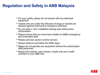
3. Regulation and Safety in ABB Malaysia
For your safety, please do not tamper with any electrical
equipment
Visitors who are under the influence of drugs or alcohol are
advised against entering the company’s premises
Do not enter a “live” installation testing area without prior
authorization
Please ensure that you have been briefed on ABB’s emergency
and evacuation plan
Please exercise caution at blind corners
Always observe and follow the traffic signs
Please do not operate any equipment without the authorization
ABB personnel
Report all incidents, near misses, unsafe acts and unsafe
condition to your ABB host
© ABB Robotic May 8, 2017
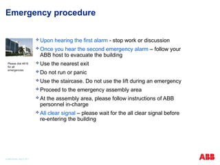
4. 5. Emergency procedure
Upon hearing the first alarm - stop work or discussion
Once you hear the second emergency alarm – follow your
ABB host to evacuate the building
Use the nearest exit
Do not run or panic
Use the staircase. Do not use the lift during an emergency
Proceed to the emergency assembly area
At the assembly area, please follow instructions of ABB
personnel in-charge
All clear signal – please wait for the all clear signal before
re-entering the building
Please dial 4816
for all
emergencies
© ABB Robotic May 8, 2017
6. 7. Course Content
Section Description
1 Introduction
2 Safety
3 System Description
4 Getting Start
5 Jogging & Coordinate System
6 IO Signal
7 Handling Programming
9 Backup and Restore
10 Event Massage
11 Restarts
12 Calibration
© ABB Robotic May 8, 2017
8. BASIC OPERATION
Course time : 0900 - 1630
Breaks : Tea/Coffee : 1030 – 1050 Lunch : 1230 – 1330 Tea/Coffee:1500 - 1520
Day 1
Safety
System Description
General
Controller
Manipulator
Operator’s Panel
Teach Pendant
Getting Start
Starting the System
Flex pendant Handling
Robot Coordinate System
Tool Coordinate System
Work Object Coordinate System
I/O Signal
Day 2
Handling Program
Program Data
TCP
Work object
Load and Run Program
- Program editing
- Modify Position
- Routine & data viewing and editing
Programming
- I/O Instruction
- Movement Instruction
- Circular movement
Day 3
Save program and module
Backup
Event Message
Restart
Calibration
© ABB Robotic May 8, 2017
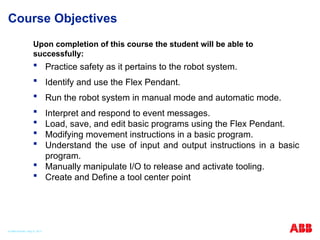
9. Course Objectives
Practice safety as it pertains to the robot system.
Identify and use the Flex Pendant.
Run the robot system in manual mode and automatic mode.
Interpret and respond to event messages.
Load, save, and edit basic programs using the Flex Pendant.
Modifying movement instructions in a basic program.
Understand the use of input and output instructions in a basic
program.
Manually manipulate I/O to release and activate tooling.
Create and Define a tool center point
Upon completion of this course the student will be able to
successfully:
© ABB Robotic May 8, 2017
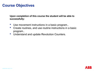
10. Course Objectives
Use movement instructions in a basic program..
Create routines, and use routine instructions in a basic
program..
Understand and update Revolution Counters.
Upon completion of this course the student will be able to
successfully:
© ABB Robotic May 8, 2017
11. 12. © ABB Robotic May 8, 2017
Robot Safety during training course
Keep fingers clear of gripper jaws when loading parts
Stand clear of robot benches when running programs
Test all program modifications in a manual mode first
Full speed modes are permitted with instructors assistance
Be cautious when releasing brakes
When inside the robot cell, make sure you have control of Pendant
13. Safety Solutions – an Overview
Pinch Points
Lock Outs
Emergency stop
Operating mode
Auto
Manual < 250 mm/s
Manual 100% (Option)
Enabling device
(Dead mans grip)
Hold-to-run
Safeguard stop
(Auto and Manual)
Limiting the workspace
Enabling device
Hold-to-run buttons
(for left or right hand)
14. Pinch Point
© ABB Robotic May 8, 2017
Evaluate the machine and its movement to identify and avoid pinch points
Pinch points are any
areas where you can
get caught between
the moving parts of a
robot and stationary
object.
Physical guards
create a barrier to
prevent you from
getting trapped or
injured in pinch point
15. LOCK OUT/TAG OUT
© ABB Robotic May 8, 2017
Proper Lock Out /Tag Out practices and procedures safeguard yourself and
other from release hazardous energy. To lock out turn the key switch to
Manual Mode, then turn the rotary disconnect to the Off position. Open
the locking mechanism on the disconnect & place your lock or a multiple
“gang lock” device on the disconnect.
16. LOCK OUT /TAG OUT (LOTO)
OBJECTIVE
Preventing the unexpected start up or release of stored energy from equipment
during maintenance and repairs to protect employees from injury
To prevent equipment from unexpectedly being set in motion and endangering
workers.
Potential hazardous energy sources must be identified ,isolated and locked
and tagged out before starting a service/ maintenance tasks
© ABB Robotic May 8, 2017
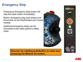
17. Emergency Stop
Pressing an Emergency Stop button will
stop the robot motion immediately.
Built-in emergency stop push buttons are
found both on the FlexPendant and Control
module.
Additional emergency stops can be
connected to the robot system’s safety
chain.
Recover by rotating pushbutton to reset and
pressing the Motors On button.
© ABB Robotic May 8, 2017
18. Operating Mode
Automatic mode
Production mode (no speed limit)
Manual mode
< 250 mm/s – max velocity 250 mm/s
100 % – Option, robot can be jogged/tested
with no speed limit.
19. © ABB Robotic May 8, 2017
Manual Full Speed (Optional)
Press and Hold down the play key, to run the program
Press and Hold down the FWD or BWD key to step
Releasing the pressed key to stops execution
1
2
20. © ABB Robotic May 8, 2017
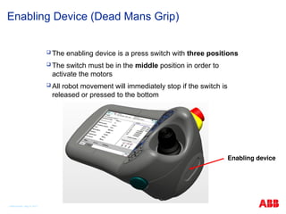
Enabling Device (Dead Mans Grip)
The enabling device is a press switch with three positions
The switch must be in the middle position in order to
activate the motors
All robot movement will immediately stop if the switch is
released or pressed to the bottom
Enabling device
21. © ABB Robotic May 8, 2017
Safeguard Stops
Your robot system can be equipped with a vast range of safeguards such as
door interlocks, safety light curtains, laser scanners and pressure mats etc.
A safeguard prevents hazardous situations by stopping the manipulator in a
controlled manner when a mechanism such as a light curtain is activated
The controller has three separate safeguarding mechanisms,
General stop (GS) Always active regardless of operating mode
Automatic stop (AS) Only active in auto mode
Superior stop (SS). Always active regardless of operating mode
22. Limiting the Workspace
To avoid the risk of getting caught between
the robot and the perimeter safety
equipment, e.g. a fence, the robot’s
workspace can be limited:
All axis can be software limited
On some robots Axis 1–3 can be limited
by adjustable mechanical stops and
controlled by limit switches
23. Working range of robot axis
All Axis are software controlled to limit their rotational range
The software stop should prevent collision at the end of axis
rotational travel
Axis 1–3 can on larger robots, can be fitted with adjustable
mechanical stops
Training robots axis are set to the default maximum range
© ABB Robotic May 8, 2017
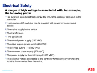
24. Electrical Safety
A danger of high voltage is associated with, for example,
the following parts:
Be aware of stored electrical energy (DC link, Ultra capacitor bank unit) in the
controller.
Units such as I/O modules, can be supplied with power from an external
source.
The mains supply/mains switch
The transformers
The power unit
The control power supply (230 VAC)
The drive system power supply (230 VAC)
The service outlets (115/230 VAC)
The customer power supply (230 VAC)
The power supply for the motors (up to 800 VDC).
The external voltage connected to the controller remains live even when the
robot is disconnected from the mains.
© ABB Robotic May 8, 2017
25. © ABB Robotic May 8, 2017
Brakes Release
The brakes on the robot motors can be manually released
Make sure the weight of the robot axis and tooling are supported
Brakes are reapplied when button is released
IRC5C controller
brake release button
26. © ABB Robotic May 8, 2017
Safety Regarding Grip Device
All grip devices must be designed so the work piece will be held even on
power failure and other disturbances in the robot system
There should be possibilities to loosen the work piece manually
Familiarize yourself with operational buttons assigned to the gripper function
27. Personal Safety
Principles should be followed in order to operate the
robot system safely:
Always operate the robot system in manual mode if personnel are inside
safeguarded space.
Always bring the Flex Pendant along when you enter safeguarded space so
that robot control is in your hands.
Watch out for rotating or moving tools such as milling cutters and saws.
Make sure those are stopped before you approach the robot.
Watch out for hot surfaces both on work pieces as well as on the robot
system. The robot's motors can become fairly hot if run for a long time.
Watch out for grippers and objects gripped. If the gripper is opened the work
piece could fall and cause injuries or damage equipment. The gripper can be
very powerful and can also cause injuries if not operated in a safe manner.
Watch out for hydraulic and pneumatic systems and live electric parts. Even
with power off residual energy in such circuits can be very dangerous.
© ABB Robotic May 8, 2017
28. 29. Accident Risks
Fault tracing
Fault tracing and repair procedure
go hand in hand .you are at your
vulnerable when you’re fixing a
robot.
Never rush through the steps and try
to work around the safety
procedures .
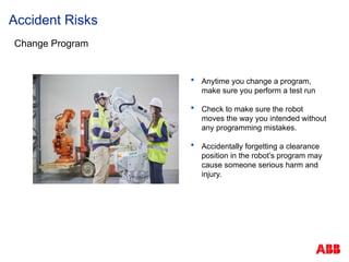
30. Accident Risks
Change Program
A program change may mean what
was safe space yesterday isn’t a
safe space today
Be sure you are following procedure
and clear communicating
information about any program
changes
31. Accident Risks
Change Program
Anytime you change a program,
make sure you perform a test run
Check to make sure the robot
moves the way you intended without
any programming mistakes.
Accidentally forgetting a clearance
position in the robot’s program may
cause someone serious harm and
injury.
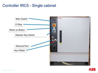
32. 33. 34. Controller IRC5 - Single cabinet
© ABB Robotic May 8, 2017
Main Switch
E-Stop
Motor on Button
Selector Key Switch
Ethernet Port
Hour Meter
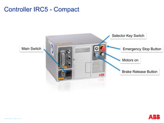
35. Controller IRC5 - Compact
© ABB Robotic May 8, 2017
Main Switch Emergency Stop Button
Motors on
Selector Key Switch
Brake Release Button
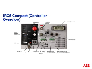
36. IRC5 Compact (Controller
Overview)
Main Power
Connector
Manipulator Connectors
Operator´s Panel Digital I/O
Safety
Presently not
used
FlexPendant
connector
Brake
Release
(IRB120 only)
Main Computer front with
CF memory, ports and PCI slots
DeviceNetTM
Lean
For external I/O units
Customer 24 V
Presently not used
Main Switch
37. IRC5 Single Cabinet (Controller Overview)
Main Computer
Unit
Field bus
adapter:
Ethernet
I/PTM
PROFIBUS
DP
PROFINET
IO
Compact Flash
mass memory
I/O units or PLC
Main Drive
Unit
Additional Drive
Unit
Front connectors
behind cover
UltraCap
Main Computer
Panel
Unit
Power Supply
Axis Computer
Hot Plug (option)
38. © ABB Robotic May 8, 2017
Example of Industrial Robot– IRB 6700
Large robot- 6 Axis
39. © ABB Robotic May 8, 2017
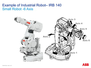
Example of Industrial Robot– IRB 140
Small Robot -6 Axis
40. © ABB Robotic May 8, 2017
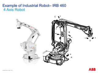
Example of Industrial Robot– IRB 460
4 Axis Robot
41. © ABB Robotic May 8, 2017
Example of Industrial Robot– IRB 360
Parallel Robot- 4 Axis
42. 43. The ABB robot family
Reach up to 3.5m
Payload up to 630kg
© ABB Robotic May 8, 2017
44. Small robot family
Payload 3kg to 10kg
IRB 120 & 120T
3kg 0.58m 7kg 0.7m
IRB 1200
5kg 0.9m
IRB 1200 IRB 140 & 140T
6kg 0.81m
IRB 1600
6kg &10kg 1.2m
IRB 1600
6kg &10kg 1.45m
IRB 1600ID
4kg 1.5m
IRB 1520ID
4kg 1.5m
© ABB Robotic May 8, 2017
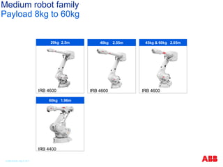
45. Medium robot family
Payload 8kg to 60kg
IRB 2600ID IRB 2600ID
8kg 2.0m 15kg 1.85m
IRB 2400 IRB 2600 IRB 2600
12kg 1.85m
12kg & 20kg 1.65m
12kg & 20kg 1.55m
© ABB Robotic May 8, 2017
46. Medium robot family
Payload 8kg to 60kg
IRB 4400
IRB 4600 IRB 4600
IRB 4600
20kg 2.5m
60kg 1.96m
45kg & 60kg 2.05m
40kg 2.55m
© ABB Robotic May 8, 2017
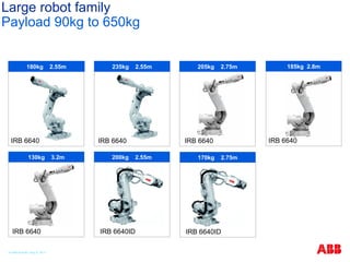
47. Large robot family
Payload 90kg to 650kg
IRB 6640
185kg 2.8m
IRB 6640
205kg 2.75m
IRB 6640
235kg 2.55m
IRB 6640
130kg 3.2m
IRB 6640ID
200kg 2.55m
180kg 2.55m
IRB 6640
IRB 6640ID
170kg 2.75m
© ABB Robotic May 8, 2017
48. Large robot family
Payload 90kg to 630kg
IRB 6660 Pre-machining
IRB 6620
IRB 6660 Press Tending
IRB 6650S
IRB 6620LX
205kg 1.9m 130kg 3.1m
150kg 2.2m 90kg & 200kg 3.0m & 3.9m
150kg 1.9m
© ABB Robotic May 8, 2017
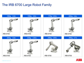
49. The IRB 6700 Large Robot Family
IRB 6700
175kg 3.05m
300kg 2.7m
IRB 6700
240kg 3.00m
IRB 6700
IRB 6700
150kg 3.2m
IRB 6700
155kg 2.8m 200kg 2.6m
IRB 6700
IRB 6700
205kg 2.8m
IRB 6700
235kg 2.65m
© ABB Robotic May 8, 2017
50. Large robot family
Payload 90kg to 630kg
400kg 2.55m
340kg 2.8m
500kg* 2.55m
IRB 7600
325kg 3.1m
150kg 3.5m
IRB 7600
* 630kg capacity
with wrist down
IRB 7600 IRB 7600
IRB 7600
© ABB Robotic May 8, 2017
51. High speed pickers Palletizers
Top loader and packer
Dedicated 4 axis robot family
Overview - picking, packing, palletizing
Serving fully
integrated
packing lines
© ABB Robotic May 8, 2017
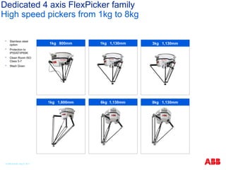
52. Dedicated 4 axis FlexPicker family
High speed pickers from 1kg to 8kg
Stainless steel
option
Protection to
IP55/67/IP69K
Clean Room ISO
Class 5-7
Wash Down
3kg 1,130mm
1kg 800mm 1kg 1,130mm
1kg 1,600mm 8kg 1,130mm
6kg 1,130mm
© ABB Robotic May 8, 2017
53. Dedicated 4 axis robot family
Top Loaders & Palletizers
IRB 260
IRB 660 IRB 660
IRB 460
IRB 760
+ Grippers
30kg 1.5m 110kg 2.4m
450kg 3.18m
180kg 3.15m 250kg 3.15m
© ABB Robotic May 8, 2017
54. Compact version
Panel mount version
Robot control family
Overview
Multi-robot control, up to 36 axis, with MultiMove
Programmable user interface with intuitive joystick control via
FlexPendant
World leading motion control with TrueMove and QuickMove
“Next generation safety” with SafeMove
Powerful connectivity through network interfaces
Remote Service option
Modular version
© ABB Robotic May 8, 2017
55. Paint robot family
With dedicated controller
IRB 52 IRB 580
IRB 5400 IRB 5400 with Rail IRC5P
All ABB paint
robots, paint
controllers
and paint
programming
units are
explosion
protected.
See data sheets
for more
information
IRB 5500
13kg 3.0m & 5.8m
7kg 1.22m & 1.45m 10kg 2.2m & 2.6m
25kg 3.1m Paint Controller
25kg up to 20m
© ABB Robotic May 8, 2017
56. Robot process and application equipment
Fully integrated with your robot
Dress Packs
Painting Track Motions
Process Cabinets Arc Welding Spot Welding
© ABB Robotic May 8, 2017
57. Robot process and application equipment
Fully integrated with your robot
© ABB Robotic May 8, 2017
RTT tracks for small robots.
IRBT 4004, 6004, 7004 tracks for large robots.
IRT tracks for other objects.
58. Robot process and application equipment
Fully integrated with your robot
Motors
Positioners Grippers
Press tending tools Gearboxes Additional axis
© ABB Robotic May 8, 2017
59. Robot process and application equipment
Fully integrated with your robot
L type positioner (5 sizes)
C type positioner (2 sizes)
R type positioner (3 sizes)
K type positioner (3 sizes)
A type positioner
(3 sizes)
B type positioner (3 sizes)
D type positioner
(2 sizes)
© ABB Robotic May 8, 2017
60. Robot process and application equipment
Fully integrated with your robot
FlexLifter (3 models)
FlexPLP (3 models)
© ABB Robotic May 8, 2017
61. Robot process and application equipment
Fully integrated with your robot
Force control
Vision Dispensing
Dusting Press synchronization Door openers
© ABB Robotic May 8, 2017
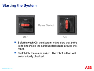
62. 63. Starting the System
Before switch ON the system, make sure that there
is no one inside the safeguarded space around the
robot.
Switch ON the mains switch. The robot is then will
automatically checked.
Mains Switch
OFF ON
© ABB Robotic May 8, 2017
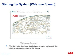
64. 65. Starting the System (Welcome Screen)
After the system has been checked and no errors are located, the
welcome message appears on the display.
Welcome Screen
© ABB Robotic May 8, 2017
66. © ABB Robotic May 8, 2017
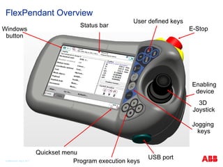
FlexPendant Overview
Status bar
User defined keys
Windows
button
Program execution keys
E-Stop
3D
Joystick
Enabling
device
USB port
Quickset menu
Jogging
keys
67. 68. © ABB Robotic May 8, 2017
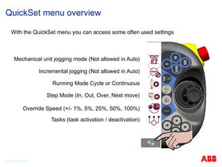
QuickSet menu overview
With the QuickSet menu you can access some often used settings
Mechanical unit jogging mode (Not allowed in Auto)
Incremental jogging (Not allowed in Auto)
Running Mode Cycle or Continuous
Step Mode (In, Out, Over, Next move)
Override Speed (+/- 1%, 5%, 25%, 50%, 100%)
Tasks (task activation / deactivation)
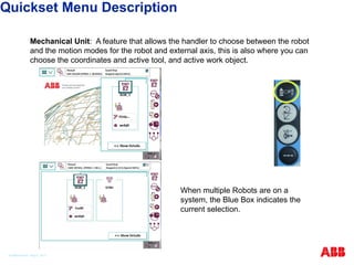
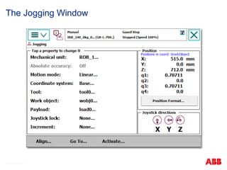
69. Mechanical Unit: A feature that allows the handler to choose between the robot
and the motion modes for the robot and external axis, this is also where you can
choose the coordinates and active tool, and active work object.
When multiple Robots are on a
system, the Blue Box indicates the
current selection.
Quickset Menu Description
© ABB Robotic May 8, 2017
70. Show/Hide Details: By Tapping on the Show Details button, your current selections
can be viewed. The button will change back to Hide Details if hit again allowing you
to minimize that screen.
The selected Coordinate system,
and Motion Mode setting is
displayed when Show Details is
pressed. Tap on one of the other
selections to change that property.
Quickset Menu Description
© ABB Robotic May 8, 2017
71. Increment: Use incremental movement to jog the robot in small steps, which
enables very precise positioning.
Each time the joystick is
deflected, the robot moves one
step(increment). If the joystick is
deflected for one or more
seconds, a sequence of steps, (at
a rate of 10 steps per second),
will be performed as long as the
joystick is deflected.
Default mode is no increment,
then the robot move continuously
when the joystick is deflected.
Quickset Menu Description
© ABB Robotic May 8, 2017
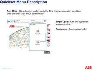
72. Run Mode: By setting run mode you define if the program execution should run
once and then stop, or run continuously
Single Cycle: Runs one cycle then
stops execution.
Continuous: Runs continuously..
Quickset Menu Description
© ABB Robotic May 8, 2017
73. Step Mode: Selecting the different Step Mode features allows you to define how the
Step-by-Step program execution will function.
Step Into: Steps into called routines
and executes them step-by-step.
Step Out: Executes the remains of
the current routine and then stops at
the next instruction in the routine
from which the current routine was
called.
Step Over: Called routines are
executed in one single step.
Next Move: Steps to the next move
instruction. Stops before and after
movement instructions, for example
to modify positions.
Quickset Menu Description
© ABB Robotic May 8, 2017
74. Speed: The Speed settings apply to the current Operating Mode. But, if you
decrease the speed in Automatic Mode, the setting also applies to Manual mode if
you change back to that mode. The current running Speed, in relation to Max, is
displayed above the buttons.
-1% & +1%: Decrease & Increase
running speed in steps of 1%.
-5% & +5%: Decrease & Increase
running speed in steps of 5%.
25%: Run at quarter speed (25%).
50%: Run at half speed (50%).
100%: Run at full speed (100%).
Quickset Menu Description
© ABB Robotic May 8, 2017
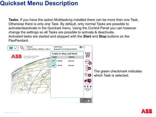
75. Tasks: If you have the option Multitasking installed there can be more than one Task.
Otherwise there is only one Task. By default, only normal Tasks are possible to
activate/deactivate in the Quickset menu. Using the Control Panel you can however
change the settings so all Tasks are possible to activate & deactivate.
Activated tasks are started and stopped with the Start and Stop buttons on the
FlexPendant.
The green checkmark indicates
which Task is selected.
Quickset Menu Description
© ABB Robotic May 8, 2017
76. 77. Exercise
1. Go to your assigned robots and practice jogging the robot
using the Quick Set button and the joystick.
2. What happens when you press the top center box on the Flex
Pendant?
3. Look at the Event Log. What was the last event that occurred?
4. Challenge: Find and Change the FlexPendant display
Brightness and contrast.
5. Challenge: Find and Change the FlexPendant for either Right
or Left handed users.
6. Practice pressing buttons on the FlexPendant. If you have any
questions ask the instructor.
© ABB Robotic May 8, 2017
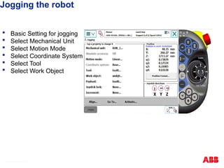
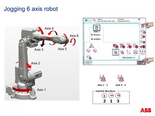
78. 79. 80. Jogging the robot
Basic Setting for jogging
Select Mechanical Unit
Select Motion Mode
Select Coordinate System
Select Tool
Select Work Object
© ABB Robotic May 8, 2017
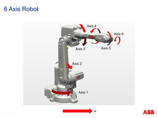
81. © ABB Robotic May 8, 2017
6 Axis Robot
Axis 2
Axis 3
Axis 4
Axis 1
Axis 2
Axis 3
Axis 4
Axis 5
Axis 6
+
82. © ABB Robotic May 8, 2017
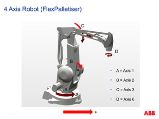
4 Axis Robot (FlexPalletiser)
• A = Axis 1
• B = Axis 2
• C = Axis 3
• D = Axis 6
A
B
C
D
+
83. © ABB Robotic May 8, 2017
3 / 4 Axis Robot (FlexPicker)
1
3
2
Y
X
4
Z Base coordinate system
84. 85. 86. © ABB Robotic May 8, 2017
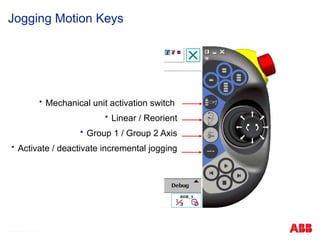
Jogging Motion Keys
Mechanical unit activation switch
Linear / Reorient
Group 1 / Group 2 Axis
Activate / deactivate incremental jogging
87. 88. 89. © ABB Robotic May 8, 2017
Incremental Jogging
Greater jogging control
Small = 0.05mm
Medium = 1mm
Large 5mm
User from 0 to 5mm
Show values to edit User
2
1
3
90. © ABB Robotic May 8, 2017
Jogging collisions
Disabling Jog supervision allows robot to be jogged after collision
‘Collision Detection’ Software option (613-1), required
Path supervision is not effected only jog supervision
Try before releasing brakes
Disabled
91. © ABB Robotic May 8, 2017
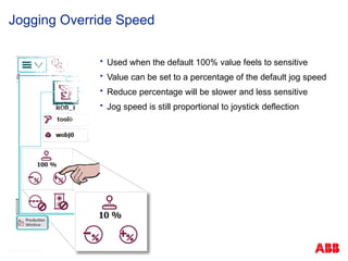
Jogging Override Speed
Used when the default 100% value feels to sensitive
Value can be set to a percentage of the default jog speed
Reduce percentage will be slower and less sensitive
Jog speed is still proportional to joystick deflection
92. 93. © ABB Robotic May 8, 2017
Jogging the Robot
-Y +Y
-X
-Z
+Z
+X
+X
+Y
+Z
-Y +Y
-X
-Z
+Z
+X
X
Z
Y
-2
-1 +1
+2
-3
+3
+1
-1
+2
-2
+3
-3
-4 +4
-5
+5
-6
+6
-4
+4
+5
-5 +6
-6
94. © ABB Robotic May 8, 2017
Z
X
Y
WorkObject
Coordinate
Coordinate System
Base
Coordinate
Z
Y
X
Tool
Coordinate
World)
Z
Y
X
Z
Y
X
95. © ABB Robotic May 8, 2017
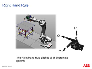
Right Hand Rule
The Right Hand Rule applies to all coordinate
systems
96. 97. © ABB Robotic May 8, 2017
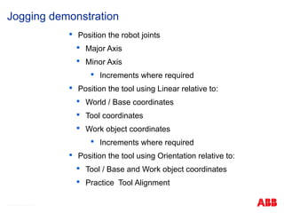
Position the robot joints
Major Axis
Minor Axis
Increments where required
Position the tool using Linear relative to:
World / Base coordinates
Tool coordinates
Work object coordinates
Increments where required
Position the tool using Orientation relative to:
Tool / Base and Work object coordinates
Practice Tool Alignment
Jogging demonstration
98. 99. © ABB Robotic May 8, 2017
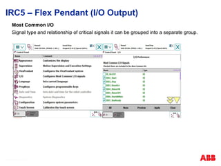
IRC5 – Flex Pendant (I/O Output)
Inputs and Outputs Window
I/O signal properties is used to view the input and output signals and their
names, values and type
Signals are configured with system parameters
100. © ABB Robotic May 8, 2017
IRC5 – Flex Pendant (I/O Output)
I/O Unit status is recognized by the system ( Board )
Individual input/output signal characteristics can retrieval and manipulate.
Manual operation is only allowable force for the individual signals.
The output signal operation Off (value 0) and On (value 1)
Input Signal Operation: First, press simulation, it can be operated via the same method.
101. © ABB Robotic May 8, 2017
IRC5 – Flex Pendant (I/O Output)
Most Common I/O
Signal type and relationship of critical signals it can be grouped into a separate group.
102. IRC5 – Flex Pendant (I/O Output)
© ABB Robotic May 8, 2017
Viewing signal
Tap Menu
Tap Inputs and Outputs
Tap View.
Select signal type
103. 104. © ABB Robotic May 8, 2017
Tool Centre Points (TCP)
+X
+Y
+Z
Wrist Coordinate system
Tool Coordinate system
105. © ABB Robotic May 8, 2017
Tool Centre Point theory
The position & movement of the robot is always relative to the active TCP.
TCP’s are defined as being somewhere at the end of the tool.
Many TCP’s may be defined, but only one active at any one time.
Can be programmed manually but only if accurate TCP values are known.
Normally the robot is used to define its TCP.
If tool is damaged or replaced, don’t modify program positions, just redefine
the tool.
106. © ABB Robotic May 8, 2017
Default Orientation (same direction as Wrist coordinate system)
TCP & Z Just Z direction defined (X stays in same plane as wrist)
TCP & Z, X both Z and X defined
From 3 to 9 approach points
Tool Centre Point Definition Methods
107. © ABB Robotic May 8, 2017
Example of TCP with default orient
No rotational difference from the wrist coordinate system
108. © ABB Robotic May 8, 2017
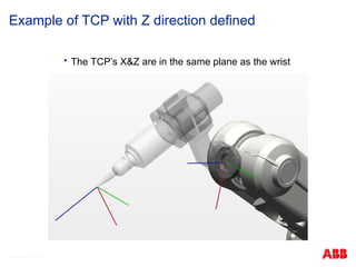
Example of TCP with Z direction defined
The TCP’s X&Z are in the same plane as the wrist
109. © ABB Robotic May 8, 2017
Example of TCP with Z&X directions defined
The TCP’s X&Z directions are rotated differently to the wrist
110. © ABB Robotic May 8, 2017
1
2
3
4
1
2
3
Plan view
4
TCP Definition – Default Orient
111. © ABB Robotic May 8, 2017
1
3
6
5
4
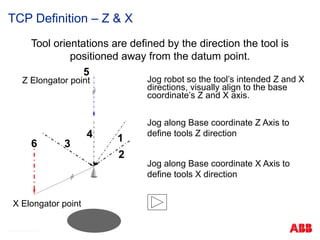
Jog robot so the tool’s intended Z and X
directions, visually align to the base
coordinate’s Z and X axis.
Jog along Base coordinate Z Axis to
define tools Z direction
Jog along Base coordinate X Axis to
define tools X direction
Z Elongator point
2
Tool orientations are defined by the direction the tool is
positioned away from the datum point.
X Elongator point
TCP Definition – Z & X
112. © ABB Robotic May 8, 2017
Tool Centre Point Definition Method
Menu
Program data
Select tooldata
Show data
New…
Name tool
Initial value or OK and then select tool in list and Edit Value
Mass:= type in kg and Centre of Gravity
Press OK
Press Edit
Select Define
Select Method and number of Points
Select Point 1, jog robot to calibration position and press Modify Position
Repeat for remaining points
Press OK
You will need to activate your TCP in the jog window
113. © ABB Robotic May 8, 2017
Exercise
Create a Tool Centre Point
Exercise 2
114. 115. © ABB Robotic May 8, 2017
Programming Introduction
Load an existing program
Introduction to basic move instructions and data
Programming move instructions
Modifying Instructions and data
Save a program
Rename a program
Delete a program
116. © ABB Robotic May 8, 2017
Program Modules.mod
Program Data
Main
Routine
Routines
<?xml version="1.0" encoding="ISO-8859-1" ?>
<Program>
<Module>MainModule.mod</Module>
<Module>ModuleA.mod</Module>
<Module>ModuleB.mod</Module>
</Program>
Program Data
Routines
Program Data
Routines
System Modules.sys
Program Task Structure
117. Rapid Program
© ABB Robotic May 8, 2017
A program is the list of command that tells robot what to do
Programming language: RAPID (Robotics Application Programming Interactive Dialogue)
- 4th generation language. RobotWare is written in C language, 3rd generation language.
Program = data + Instruction/commands (Instruction/commands are handled in units of
routines)
A program operates in conjunction with a program module and a system module, and
there is only one program in the program memory. (Extension: *. pgf)
118. 119. © ABB Robotic May 8, 2017
Modules
A module contains routines and data’s.
The module that contains the main routine is the MainModule
System modules are always present in memory and can be used to save your
default data
Filename extensions are
XXXXX.mod Program Module
XXXXX.sys System Module
XXXXX.pgf Program File
120. © ABB Robotic May 8, 2017
Routines
Repetitive instruction sequences, that occur frequently in the program, should
form their own routines.
Routines separate the program into smaller more easily understood parts,
these can then be called anywhere in the program using the ProcCall
instruction.
A Max of 16 characters are allowed for naming routines, meaningful names
will make the program easier to follow and operate.
Routines can be tested by moving the Program Pointer to a routine. (Debug)
Routines are called within the program using the instruction ‘Procall’
121. © ABB Robotic May 8, 2017
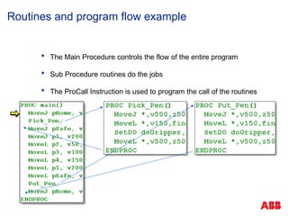
Routines and program flow example
The Main Procedure controls the flow of the entire program
Sub Procedure routines do the jobs
The ProCall Instruction is used to program the call of the routines
122. © ABB Robotic May 8, 2017
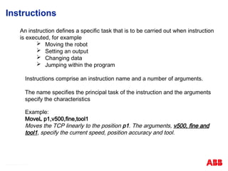
Instructions
An instruction defines a specific task that is to be carried out when instruction
is executed, for example
Moving the robot
Setting an output
Changing data
Jumping within the program
Instructions comprise an instruction name and a number of arguments.
The name specifies the principal task of the instruction and the arguments
specify the characteristics
Example:
MoveL p1,v500,fine,tool1
Moves the TCP linearly to the position p1. The arguments, v500, fine and
tool1, specify the current speed, position accuracy and tool.
123. © ABB Robotic May 8, 2017
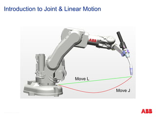
Introduction to Joint & Linear Motion
Move L
Move J
124. MoveJ is used to move the robot quickly from point to point
The movement will not be in a straight line.
© ABB Robotic May 8, 2017
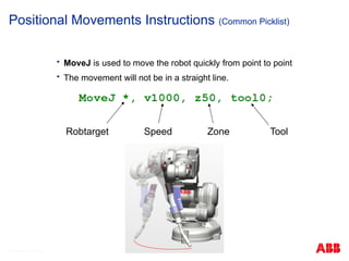
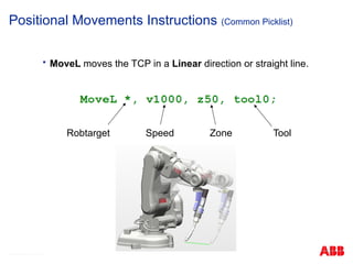
Positional Movements Instructions (Common Picklist)
Robtarget Speed Zone Tool
125. © ABB Robotic May 8, 2017
Positional Movements Instructions (Common Picklist)
MoveL moves the TCP in a Linear direction or straight line.
Robtarget Speed Zone Tool
126. Zones
© ABB Robotic May 8, 2017
z
MoveL p40, v1000, z50, tool0;
MoveL p30, v400, z20, tool0;
Zone data describes how close to the destination position
the axes must be before the next instruction can be executed
Zone size
127. © ABB Robotic May 8, 2017
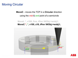
Moving Circular
MoveC - moves the TCP in a Circular direction
using the mid & end point of a semicircle
MoveL *, v100, fine, tPen WObj:=wobj1;
MoveC *, *, v100, z10, tPen WObj:=wobj1;
mid
end
128. © ABB Robotic May 8, 2017
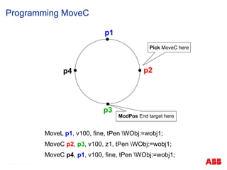
Programming MoveC
p1
p2
p3
p4
ModPos End target here
Pick MoveC here
MoveL p1, v100, fine, tPen WObj:=wobj1;
MoveC p2, p3, v100, z1, tPen WObj:=wobj1;
MoveC p4, p1, v100, fine, tPen WObj:=wobj1;
129. Input Instruction
© ABB Robotic May 8, 2017
Input processing instructions are to wait until you are satisfied the specified conditions.
Conditions can be such signal conditions, the time, the logical operation.
WaitDI di05_AutoReady, 1;
WaitTime 0.5;
WaitUntil di06_Ready = 1;
WaitUntil di05=1 AND di07=0;
WaitUntil di02=1 OR di03=1...;
Signal state
Signal Name
130. 131. 132. 133. © ABB Robotic May 8, 2017
Creating New programs
New Programs can be created in the Program Editor
Program names can not start with a number
If a program allready exists, it will be overwritten
New programs are temporaraly called ’NewProgramName’
A ‘main’ routine is created within a ‘MainModule’
134. Loading Programs
Loading whole programs will overwrite existing
programs
Each task will have its own program
© ABB Robotic May 8, 2017
135. 136. Creating a new Module
ABB menu
Tap Program Editor.
Tap Modules.
Tap File, then tap New Module.
Tap ABC... and use the soft keyboard to enter the new module's name.
Then tap OK
Select which type of module to be created:
• Program
• System
Then tap OK.
© ABB Robotic May 8, 2017
137. 138. How to create and program routines.
Must be in the Program Editor.
Tap Routines : File
New Routine : Tap “ABC…”
to change the name.
Tap OK.
Select the routine.
Tap Show routine.
Creating Routines
© ABB Robotic May 8, 2017
139. To add instructions to your program:
Tap Add Instruction
Jog robot into position
Tap MoveJ or MoveL
Jog robot to next position
Repeat
Inserting Move Instructions
© ABB Robotic May 8, 2017
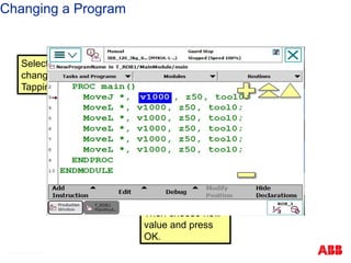
140. 141. Select the instruction or target to be changed (Step is recommended)
Jog robot to the desired position
Press Modify Position
Modify Position
© ABB Robotic May 8, 2017
142. 143. 144. 145. 146. Create a new routine called PickPen
Activate your TCP
Program the robot to pick up the pen
Test this routine (debug ‘PP to routine’)
Copy this routine and edit the output instruction to put the pen down
Test the duplicated routine (debug ‘PP to routine’)
Call these routines within your main routine (ProCall instruction)
Test your Main Routine (debug ‘PP to main’)
Save your program as ‘Exercise_3’
Routines Exercise
© ABB Robotic May 8, 2017
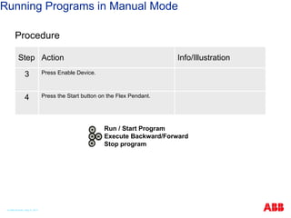
147. 148. 149. Running Programs in Manual Mode
Procedure
Step Action Info/Illustration
1 Switch the robot to Manual Mode.
2
DANGER!
Before running the robot, please observe the safety
information in section DANGER – moving
manipulators are potentially lethal!
© ABB Robotic May 8, 2017
150. Running Programs in Manual Mode
Procedure
Step Action Info/Illustration
3 Press Enable Device.
4 Press the Start button on the Flex Pendant.
Run / Start Program
Execute Backward/Forward
Stop program
© ABB Robotic May 8, 2017
151. Starting Execution
Procedure
Step Action Info/Illustration
1 To run a selected execution use the “Run" button
on the Flex Pendant's hardware button key set.
Run / Start Program
Execute Backward/Forward
Stop program
© ABB Robotic May 8, 2017
152. Stepping Instruction by Instruction
In Manual Mode, the program may be executed step-by-step forwards
or backwards
There are number of dedicated hardware buttons on the FlexPendant
Programmable button 1. How to define it's function is in the
IRC5 Pocket Guide.
Programmable button 2. How to define it's function is in the
IRC5 Pocket Guide.
Programmable button 3. How to define it's function is in the
IRC5 Pocket Guide.
Programmable button 4. How to define it's function is in the
IRC5 Pocket Guide.
RUN button. Starts program execution.
STEP BACKWARDS button. Steps the program one
instruction backwards.
STEP FORWARDS button. Steps the program one
instruction forwards.
STOP button. Stops the program execution.
© ABB Robotic May 8, 2017
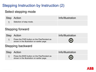
153. Stepping Instruction by Instruction (2)
Select stepping mode
Step Action Info/Illustration
1 Selection of step mode.
Stepping forward
Step Action Info/Illustration
1 Press the FWD button on the FlexPendant as
shown in the illustration on earlier page.
Stepping backward
Step Action Info/Illustration
1 Press the BWD button on the FlexPendant as
shown in the illustration on earlier page.
© ABB Robotic May 8, 2017
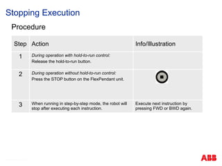
154. Stopping Execution
Procedure
Step Action Info/Illustration
1 During operation with hold-to-run control:
Release the hold-to-run button.
2 During operation without hold-to-run control:
Press the STOP button on the FlexPendant unit.
3 When running in step-by-step mode, the robot will
stop after executing each instruction.
Execute next instruction by
pressing FWD or BWD again.
© ABB Robotic May 8, 2017
155. 156. Saving program in IRC5
A folder with the same name as the program is created
This folder contains the MainModule, Sub modules and the program file
The program file (.pgf),is an extensible mark-up language, ‘XML’, file that lists all
program modules in the task
System Modules are NOT saved
© ABB Robotic May 8, 2017
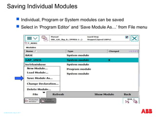
157. 158. Saving Individual Modules
Individual, Program or System modules can be saved
Select in ‘Program Editor’ and ‘Save Module As…’ from File menu
© ABB Robotic May 8, 2017
159. 160. Exercise
1. Go to your assigned robots and create a simple program as described in
this section. Then test your program. Each student should make their own
program. (Do not use I/O until all participants have created and tested their
programs.)
2. What happens when you press the E-Stop button while the robot is
running? Can you restart the robot from where it stopped?
3. Save the program to the Flash Drive.
4. Practice pressing buttons on the FlexPendant. If you have any questions
ask the instructor.
© ABB Robotic May 8, 2017
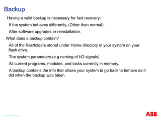
161. 162. Backup
Having a valid backup is necessary for fast recovery:
If the system behaves differently. (Other than normal)
After software upgrades or reinstallation.
What does a backup contain?
All of the files/folders stored under Home directory in your system on your
flash drive.
The system parameters (e.g naming of I/O signals)
All current programs, modules, and tasks currently in memory.
A backup contains the info that allows your system to go back to behave as it
did when the backup was taken.
© ABB Robotic May 8, 2017
163. 164. Backup and Restore – Backup the System
ABB recommends performing a backup:
Before installing new Robot Ware
Before making any major changes to instructions and/or parameters
to facilitate the previous setting
After making any changes to instructions and/or parameters and
testing the new settings to retain the new settings
Remarks:
Always
Give your backup a good name. Push to go to the key board to
type the name of the backup.
Pay attention to the Backup Path, this is the location where the
backup will be stored. Push the … to change the location.
You should create a Backup folder to store the file in.
© ABB Robotic May 8, 2017
165. 166. 167. 168. Event Messages are divided into.
Information
Example: Hold to run must be pressed.
Information is stored in the log.
Warning
Example : Manual movement full speed is selected.
The operator is informed about a potential risk.
Error
Example : Motor On when Emergency Stop is active.
The system cannot operate before a measure is carried
out.
Introduction
© ABB Robotic May 8, 2017
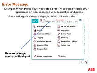
169. 170. 171. Error Message
Example: When the computer detects a problem or possible problem, it
generates an error message with description and action.
Unacknowledged message is displayed in red on the status bar
Unacknowledged
message displayed
172. Event Message Content
An Event Message consists of
Description
Consequences (optional)
Probable causes (optional)
Action (optional)
Tap arrow to scroll down
in message!
© ABB Robotic May 8, 2017
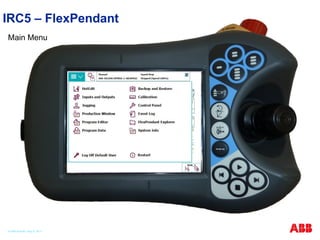
173. Reading Event Logs on the FlexPendant
Via ABB - Main menu
Tap status bar – Short cut
Tap on Status Bar to see
Event log.
Or Tap ABB then Event
Log to see Event log.
174. 175. Scroll the list with the yellow arrows
Tap on a specific message to get more information
Event Log
© ABB Robotic May 8, 2017
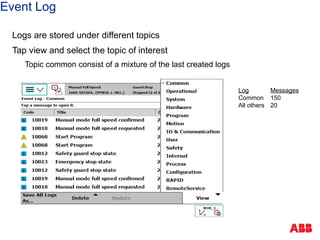
176. Event Log
Logs are stored under different topics
Tap view and select the topic of interest
Topic common consist of a mixture of the last created logs
Log Messages
Common 150
All others 20
177. Event Categories
Category Error number Area__________________
Operational 10xxx Operational Status
System 20xxx Panel unit
Hardware 30xxx Board Failure
Program 40xxx Programming
Motion 50xxx Movement problem
Operation 60xxx Flex Pendant Handling
I/O communication 70xxx I/O board communication errors
ArcWeld 11xxxx Process
SpotWeld 12xxxx Process
Paint 13xxxx Process
Refer to the error number when support is
needed!
© ABB Robotic May 8, 2017
178. 179. 180. 181. Restart (Warm Start)
When: New hardware, SYSFAIL or change in configuration
Result: Current system is restarted. Program pointer are restored
Reset System (I- start)
When: Add RobWare for a new process
All saved, Restart with default parameters.
Modules & program not loaded
Reset Rapid (P-Start)
When: E.g. Changing data in parallel tasks
All data saved on image file for loading purpose
RAPID programs not reloaded
Summary of Restart Alternatives
© ABB Robotic May 8, 2017
182. Summary of Restart Alternatives
Start Boot Application (E-start)
When: Change to an existing system: E.g: Glue to Arcweld
All data are saved on an image file, for loading purpose only
C-Start (Cold start) Removes all user inputs and the robot software
When: E.g: A new BaseWare for a system shall be loaded
All data is erased. A boot is necessary if no other system exists in the controller
© ABB Robotic May 8, 2017
183. Special Restart Alternatives
Shutdown
When: The UPS system is not working
An image file is carried out as a normal Power Off
To start: Turn Power Off & On to restart the system
Revert to last Auto Saved (B-Start)
When: E.g. Recommend action from an error message
Returns the system to the state after the most recent shutdown by either Power
Off or Shutdown
In this case no saving is carried out as for Warm Start
Note! These alternatives are intended for special use only!
© ABB Robotic May 8, 2017
184. 185. Fine Calibrate or Rev.Count update?
Rev.Count update can easily be made with no special
tools.
Fine calibration needs special tools.
Calibration – IRC5
© ABB Robotic May 8, 2017
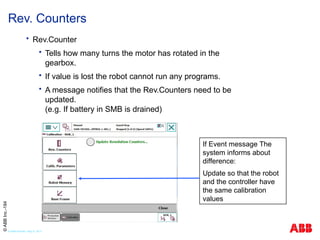
186. Rev.Counter
Tells how many turns the motor has rotated in the
gearbox.
If value is lost the robot cannot run any programs.
A message notifies that the Rev.Counters need to be
updated.
(e.g. If battery in SMB is drained)
Rev. Counters
If Event message The
system informs about
difference:
Update so that the robot
and the controller have
the same calibration
values
©
ABB
Inc.-184
© ABB Robotic May 8, 2017
187. Updating Rev. Counters
1. Use the Joy stick and
Move the Robot to
the Calibration
Position and align
the witness marks.
© ABB Robotic May 8, 2017
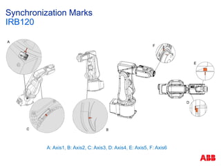
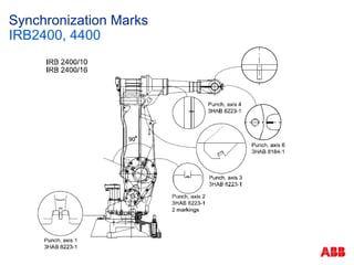
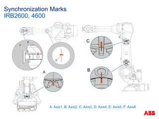
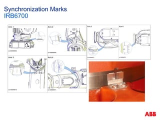
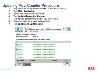
188. 189. 190. 191. 192. 193. 194. 195. 196. Updating Rev. Counter Procedure
1. Jog the robot to the witness marks / Calibration position.
2. Tap ABB : Calibration
3. Select the robot to be calibrated.
4. Tap Update Revolution Counter
5. Tap YES to confirm this is what you want to do.
6. If needed select the axes to be updated.
7. Tap Update and Update again.
© ABB Robotic May 8, 2017
197. MoveAbsJ
Create a new routine (GotoCalib)
Insert MoveAbsJ instruction
Choose star position, Debug / View Value, put all 6 axis
to zero
Checking Robot Calibration
© ABB Robotic May 8, 2017
198. Fine Calibration
Tells the current angle of motor shaft when robot is in
sync position
Is tuned in by ABB or on site with special equipment
Only needs to be retuned if a motor / gearbox is
replaced
Fine Calibration
Requires special tools!
Cannot be made correctly
by eye Measurement.
© ABB Robotic May 8, 2017
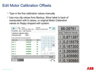
199. Type in the fine calibration values manually
Use moc.cfg values from Backup, Silver label in back of
manipulator with 6 values, or original Motor Calibration
values on floppy shipped with system.
Edit Motor Calibration Offsets
© ABB Robotic May 8, 2017
200. 201. For Emergency Service, Spare Parts, Tech
Support, Questions, Comments, Complaints….
+603 5628 4888
© ABB Robotic May 8, 2017
202. Editor's Notes #15 Most industry personnel have had Lock Out Tag Out training. We want to emphasize this training and the proper procedures on the ABB robot. #33 Explicar sobre controladores, unidade de programação e manipuladores. #34 Mostrar principais componentes do painel. #35 Mostrar painel compacto. #38 Exemplo de robô industrial.
IRB6640
Robô de grande porte com capacidade de carga indo de 130Kg à 235Kg dependendo da versão.
Robô de 6 eixos, ou seja, 6 graus de liberdade como a maioria dos robôs industriais. A ABB possui alguns robôs de 4 eixos, geralmente utilizados para aplicações de paletização onde não existe a necessidade de inclinar o produto.
Robô com alcaide de 2.55m até 3.2m dependendo da versão.
Ilustração dos eixos do robô IRB6640.
Mostrar os movimentos de cada eixo.
Eixos 1, 2 e 3 são os eixos principais do robô e são usados para movimentar o robô no espaço.
Eixos 4, 5 e 6 são o punho do robô e são usados para orientar a ferramenta do robô, ou seja, mudar o angulo de trabalho.
#39 Exemplo de robô industrial.
IRB140 robô de pequeno porte com capacidade de carga de 5Kg.
Robô de 6 eixos, ou seja, 6 graus de liberdade.
Alcance de 0.81 metros.
Ilustração dos eixos do robô IRB140.
Mostrar os movimentos de cada eixo.
Eixos 1, 2 e 3 são os eixos principais do robô e são usados para movimentar o robô no espaço.
Eixos 4, 5 e 6 são o punho do robô e são usados para orientar a ferramenta do robô, ou seja, mudar o angulo de trabalho.
#40 Exemplo de robô industrial.
IRB460 robô de médio porte com capacidade de carga de 110Kg.
Robô de 4 eixos, ou seja, 4 graus de liberdade. Geralmente usado em paletização
Alcance de 2.4 metros.
Ilustração dos eixos do robô IRB460.
Mostrar os movimentos de cada eixo.
Eixos 1, 2 e 3 são os eixos principais do robô e são usados para movimentar o robô no espaço.
Eixo 6 é usado para girar o produto.
#41 Exemplo de robô industrial.
IRB360 robô de pequeno porte com capacidade de carga de até 3Kg.
Robô de 4 eixos, ou seja, 4 graus de liberdade. Geralmente usado em aplicações de Pick’n’Place
Alcance de 1.13 metros.
Ilustração dos eixos do robô IRB360.
Mostrar os movimentos de cada eixo.
Eixos 1, 2 e 3 são os eixos principais do robô e são usados para movimentar o robô no espaço.
Eixo 4 é usado para girar o produto.
#43 From 1kg to 630kg.
From .81m to 3.5m reach.
#46 IRB 4400 is an old robot design but it is retained in the range for high demand rigidity applications like heavy materials removal applications, such as, Machining . #49 The new work horse of the Large Robot Family. The IRB 6700 is the seventh generation of ABB large robots.
. #57 ABB provides track type positioners for all types of uses. #59 ABB has a full range of positioners for moving parts in and out of a cell or for moving parts to different positions. These are used most for Arc welding. #60 These are newer product lines for leaner manufacturing. #61 Day one. 11:00 AM
This is a good time to take a lab tour to actually see some of the products desribed.
Day one. 11:30 AM Lunch #67 - HotEdit is used to tune programmed positions. This can be done in all operating
modes and even while the program is running. Both coordinates and orientation
can be tuned. HotEdit can only be used for named positions of the type robtarget.
-Inputs and outputs, I/O, are signals used in the robot system.
-The Jogging functions are found in the Jogging window. The most commonly used
are also available under the Quickset menu.
-The Program Editor is where you create or modify programs. You can open more
than one window of the Program Editor
-The Program Data view contains functions for viewing and working with data types
and instances. You can open more than one window of the Program Data, which
can be useful when working with many instances or data types.
-The Production Window is used to view the program code while the program is running.
-The Backup and Restore menu is used for performing backups and restoring the system.
-The Calibration menu is used to calibrate mechanical units in the robot system.
-The Control Panel contains functions for customizing the robot system and the FlexPendant.
-The FlexPendant Explorer is a file manager, similar to Windows Explorer, with
which you can view the file system on the controller. You can also rename, delete,
or move files or folders.
-System Info displays information about the controller and the loaded system. Here
you can find the RobotWare version and options currently in use, current keys for
control and drive modules, network connections and so on.
-Robot systems are often operated without any personnel present. The logging
function is a way to store information about past events for future reference in
order to facilitate trouble shooting.
#80 What is jogging?
To jog is to manually position or move robots or external axes using the FlexPendant
joystick #93 Mostrar tipos de movimento #94 Falar sobre os sistemas de coordenada, qual a diferença entre eles e como seleciona-los #95 Falar sobre a regra da mão direita #126 Mostrar o funcionamento da zona e da velocidade