This document provides an overview and introduction to IPv6 fundamentals, including:
- The history and basics of IPv6 including addressing, headers, and essential functions like neighbor discovery.
- Methods for IPv6 integration and transition such as tunneling (6to4, ISATAP) and translation (NAT-PT).
- IPv6 routing protocols (RIPng, OSPF, BGP) and network management standards and tools.
- Other topics covered include multicast, security, mobility, and coexistence of IPv4 and IPv6. Configuration examples are provided for common IPv6 implementations.
The document is intended as a guide for network engineers and administrators to understand IPv6 technologies


![Chapter 1 Introduction
Chapter 1
Introduction
Internet Protocol version 6 (IPv6) is the new generation of the basic protocol of the Internet. IP is the
common language of the Internet, every device connected to the Internet must support it. The current
version of IP (IP version 4) has several shortcomings which complicate, and in some cases present a
barrier to, the further development of the Internet. The coming IPv6 revolution should remove these
barriers and provide a feature-rich environment for the future of global networking.
1.1 The History of IPv6
The IPv6 story began in the early nineties when it was discovered that the address space available in
IPv4 was vanishing quite rapidly. Contemporary studies indicated that it may be depleted within the
next ten years – around 2005! These findings challenged the Internet community to start looking for a
solution. Two possible approaches were at hand:
1. Minimal: Keep the protocol intact, just increase the address length. This was the easier way
promising less pain in the deployment phase.
2. Maximal: Develop an entirely new version of the protocol. Taking this approach would enable
incorporating new features and enhancements in IP.
Because there was no urgent need for a quick solution, the development of a new protocol was chosen.
Its original name IP Next Generation (IPng) was soon replaced by IP version 6 which is now the
definitive name. The main architects of this new protocol were Steven Deering and Robert Hinden.
The first set of RFCs specifying the IPv6 were released at the end of 1995, namely, RFC 1883:
Internet Protocol, Version 6 (IPv6) Specification [RFC1883] and its relatives. Once the definition was
available, implementations were eagerly awaited. But they did not come.
The second half of the nineties was a period of significant Internet boom. Companies on the market
had to solve a tricky business problem: while an investment in IPv6 can bring some benefits in the
future, an investment in the blossoming IPv4 Internet earns money now. For a vast majority of them it
was essentially a no-brainer: they decided to prefer the rapid and easy return of investments and
developed IPv4-based products.
Another factor complicating IPv6 deployment was the change of rules in the IPv4 domain. Methods to
conserve the address space were developed and put into operation. The most important of these was
Classless Inter-Domain Routing (CIDR). The old address classes were removed and address
assignment rules hardened. As a consequence, newly connected sites obtained significantly less
addresses than in previous years.
The use of CIDR may well have delayed the need for IPv6 in the eyes of many people, but not in all.
Somewhat perversely, the use of CIDR accelerated the perception of a lack of address space in the
3](https://image.slidesharecdn.com/ipv6deployment-guide-110112200202-phpapp01/75/IPv6-Deployment-Guide-17-2048.jpg)
![Chapter 2 IPv6 Basics
Chapter 2
IPv6 Basics
Inside this chapter we cover the protocol basics: the datagram format, the headers and related
mechanisms. You will see that these aspects have been simplified significantly in comparison to IPv4
to achieve higher performance of datagram forwarding.
2.1 Datagram Header
The core of the protocol is naturally the datagram format defined in RFC 2460 [RFC2460]. The
datagram design focused mainly on simplicity - to keep the datagram as simple as possible and to keep
the size of the headers fixed. The main reason for this decision was to maximise processing
performance - simple constant size headers can be processed quickly, at or very close to wire-speed.
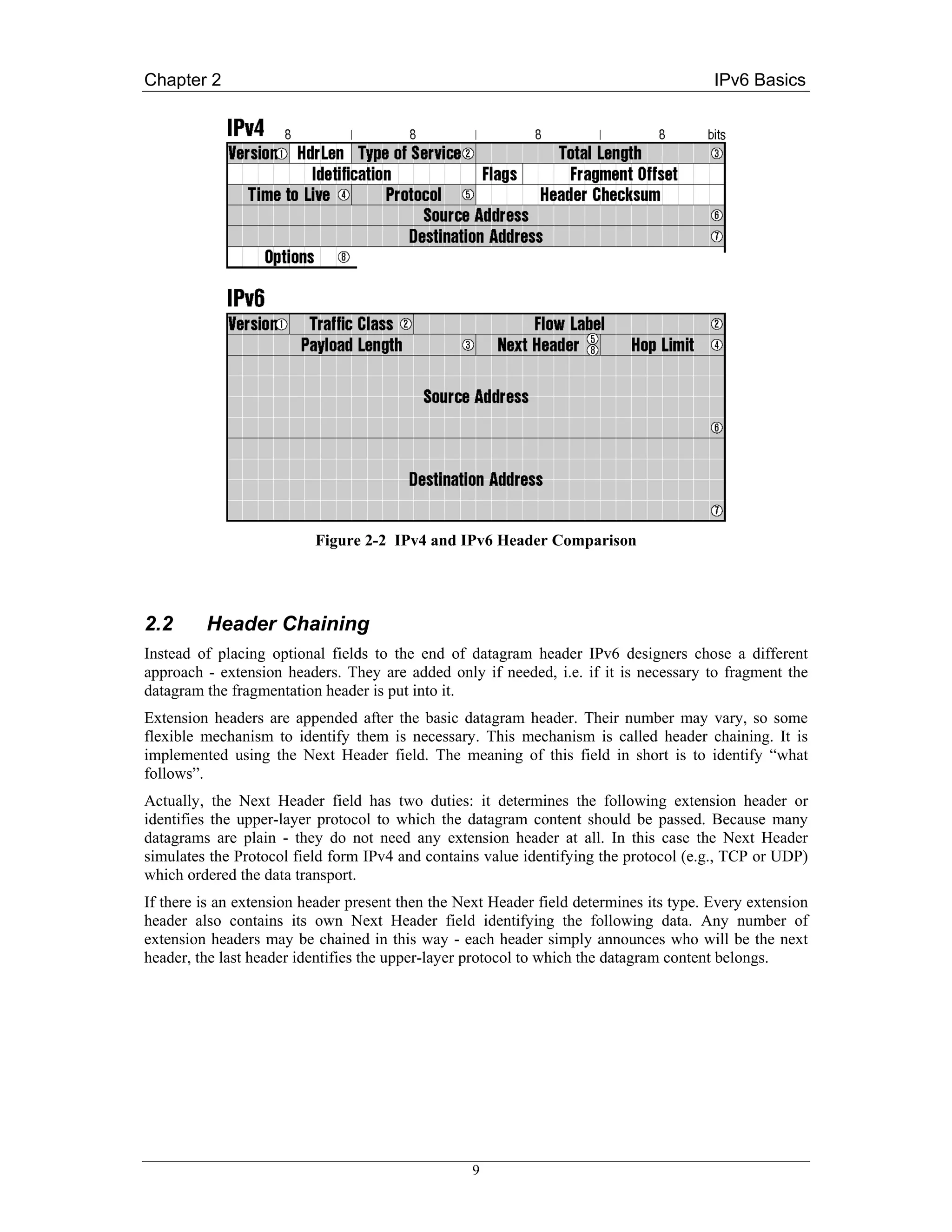
The IPv4 header format contains a lot of fields including some unpredictable optional ones leading to
fluctuating header sizes. IPv6 shows a different approach: the basic header is minimised and a constant
size. Only essential fields (like addresses or datagram length) are contained. Everything else has been
shifted aside into so called extension headers, which are attached on demand - for example a mobile
node adds mobility related extension headers to its outgoing traffic.
Figure 2-1 Basic IPv6 Datagram Header
The basic datagram header format is showed in Figure 2-1. The contents of individual fields are
following:
7](https://image.slidesharecdn.com/ipv6deployment-guide-110112200202-phpapp01/75/IPv6-Deployment-Guide-21-2048.jpg)

![Chapter 3 Addressing
Chapter 3
Addressing
Rapid depletion of the available IPv4 address space was the main initiator of IPv6. In consequence, the
demand to never again have to develop a new protocol due to the lack of addresses was one of the
principal requirements to the new address space design. Let’s look how it was fulfilled.
The basic rules of IPv6 addressing are laid down by RFC 3513 [RFC3513]. Some accompanying
RFCs define the specialties and rules for specific address types.
3.1 Addressing Essentials
The address length has been increased significantly to expand the available address space. The IPv6
address is 128 bits (or 16 bytes) long, which is four times as long as its predecessor. Because every
single bit of added address length doubles the number of addresses available, the size of the IPv6
address space is really huge. It contains 2128 which is about 340 billion billion billion billion different
addresses which definitely should suffice for a very long time.
Addresses are written using 32 hexadecimal digits. The digits are arranged into 8 groups of four to
improve the readability. Groups are separated by colons. So the written form of IPv6 address looks
like this:
2001:0718:1c01:0016:020d:56ff:fe77:52a3
As you can imagine DNS plays an important role in the IPv6 world, because the manual typing of
IPv6 addresses is not an easy thing. Some abbreviations are allowed to lighten this task at least a little.
Namely: leading zeroes in every group can be omitted. So the example address can be shortened to
2001:718:1c01:16:20d:56ff:fe77:52a3
Secondly, a sequence of all-zero groups can be replaced by pair of colons. Only one such abbreviation
may occur in any address, otherwise the address would be ambiguous. This is especially handy for
special-purpose addresses or address prefixes containing long sequences of zeroes. For example the
loopback address
0:0:0:0:0:0:0:1
may be written as
::1
which is not only much shorter but also more evident. Address prefixes are usually written in the form:
prefix::/length
Where prefix defines the value of bits in the address beginning and length contains the number of
important bits from the start. Because the rest of the prefix is not important, zeroes are used in this part
15](https://image.slidesharecdn.com/ipv6deployment-guide-110112200202-phpapp01/75/IPv6-Deployment-Guide-29-2048.jpg)
![Chapter 3 Addressing
of the address, and the “::” abbreviation is deployed. So for example prefix dedicated to the 6to4
transition mechanism is
2002::/16
which means that the starting 16 bits (two bytes, corresponding to one group in the written address)
have to contain value 2002 (hexadecimal), the rest is unimportant.
Not all addresses are handled equally. IPv6 supports three different address types for which the
delivery process varies:
Unicast (individual) address
identifies one single network interface (typically a computer or similar device). The packet is
delivered to this individual interface.
Multicast (group) address
identifies group of interfaces. Data must be delivered to all group members.
Anycast (selective) address
also identifies a group of network interfaces. But this time the packet is delivered just to one
single member of the group (to the nearest one).
Broadcast as an address category is missing in IPv6, because broadcast is just a special kind of
multicast. Instead of including a separate address category, IPv6 defines some standard multicast
addresses corresponding to the commonly used IPv4 broadcast addresses. For example ff02::1 is the
multicast address for all nodes connected to given link.
Let’s look at the features of different address types in more detail.
3.2 Unicast Addresses
This is the most important address type because unicast addresses are the “normal” addresses
identifying the common computers, printers and other devices connected to the network.
Let’s look at the most important subtype of unicast addresses first - at the global unicast addresses
defined by RFC 3587 [RFC3587]. The internal unicast address structure defined by this RFC is quite
simple. It contains just three parts as depicted in Figure 3-1: global routing prefix, subnet ID, and
interface ID.
Figure 3-1 Structure of the Global Unicast Address
Global routing prefix
is the network address in IPv4 parlance. This address prefix identifies uniquely the network
connected to the Internet.
Subnet ID
is the identifier of a subnet. The end-network may be partitioned into to subnets (for example
every building of some institution may hold separate subnet). This part of the address serves to
identify individual subnets.
16](https://image.slidesharecdn.com/ipv6deployment-guide-110112200202-phpapp01/75/IPv6-Deployment-Guide-30-2048.jpg)
![Chapter 3 Addressing
Interface ID
holds the identifier of single network interface. Interface identifiers are unique inside the same
subnet only, there may be devices holding the same interface ID in different subnets. Internet
standards request the modified EUI-64 (described below) to play the role of interface ID.
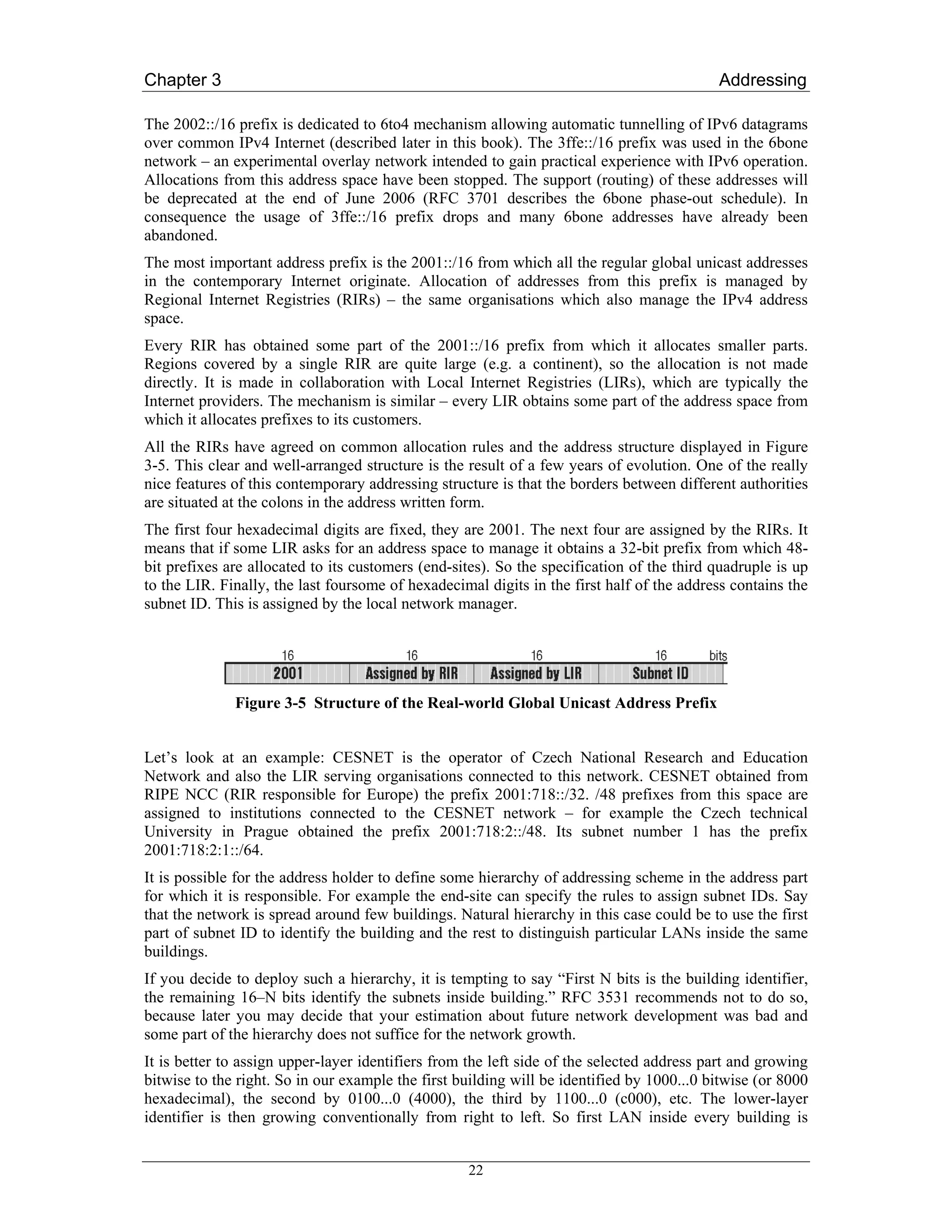
In reality the address structure is even more simple, because all used addressing schemes have the
common length of the global prefix (48 bits) and subnet identifier (16 bits). In consequence the typical
unicast address has the structure showed in Figure 3-2.
Figure 3-2 Real-world Structure of the Global Unicast Address
Not all unicast addresses are global. Some of them are limited just to a single physical (layer 2)
network. These link-local addresses are distinguished by prefix fe80::/10. They can be used for intra-
link communication only – both the sender and recipient of the datagram must be connected to the
same local network. A router must not forward any datagram having such a destination address.
Theses addresses are used in some mechanisms, such as the autoconfiguration of network parameters.
RFC 3513 actually defines two scoping levels: link-local (prefix fe80::/10) and site-local (fec0::/10)
addresses. But due to a long-term lack of consensus on the definition of “site” RFC 3879 [RFC3879]
deprecated the usage of site-local addresses and prohibits new IPv6 implementations to handle the
fec0::/10 prefix. RFC 3879 states that the given prefix is reserved for potential future usage.
Note:
Although, in theory, site-local addresses have been deprecated by RFC 3879, many IPv6
implementations and IPv6 applications still use site-local prefixes and this will probably remain
true for some time. Indeed, some of the configuration examples in this book contain site-local
addresses.
Consequently, unicast addresses have just two scope levels: link-local (starting with fe80::/10) or
global (all the others).
3.3 Interface Identifier – Modified EUI-64
Providing 64 bits to identify the interface in the scope of a single subnet seems to be a huge
extravagance. For example 48 bits are sufficient for Ethernet addresses which are world-wide unique.
Subnets for which 16 bits would not suffice to identify all the nodes are hard to imagine. On the other
hand this 64-bit long interface identifier simplifies significantly some autoconfiguration mechanisms.
RFC 3513 specifies the use of modified EUI-64 identifiers in this part of the IPv6 address. EUI-64 is a
network interface identifier defined by the IEEE. The modification deployed in IPv6 is related to 7th
bit of the 64-bit identifier. This bit distinguishes global identifiers (world-wide unique) from the local
ones (unique only in the scope of single link). The value of this bit is inverted in IPv6 addresses.
Hence the value 0 of this bit means a local identifier, while a value of 1 indicates a global ID.
How do we determine the value of this final part of the IPv6 address? The answer depends on the
lower-layer address which the corresponding interface has. Basic rules are following:
Interface has an EUI-64 identifier
This is the simplest case. The 7th bit of the existing EUI-64 identifier is inverted and the
resulting value is used.
17](https://image.slidesharecdn.com/ipv6deployment-guide-110112200202-phpapp01/75/IPv6-Deployment-Guide-31-2048.jpg)
![Chapter 3 Addressing
Interface has a MAC (Ethernet) address
There is a simple algorithm converting the MAC address into a modified EUI-64: the global
flag (7th bit) of the MAC address is inverted and the value fffe is inserted between the 3rd and
4th byte of the MAC address. For example the MAC address 00:8c:a0:c2:71:35 is converted
to interface ID 028c:a0ff:fec2:7135 (the conversion is illustrated in Figure 3.3).
Otherwise
In other cases the network manager simply assigns some identifier to the interface. Typically
some simple identifiers (like 0:0:0:1 and 0:0:0:2) are used. Such artificial identifiers are used
for example for serial lines, which do not provide any values usable as a ground for the
identification.
Figure 3-3 Conversion of MAC Address to Interface Identifier
From a technical point of view this is a perfect working mechanism. But there is a hidden drawback - a
threat to privacy. Since a common computer is equipped by some MAC-addressed network card, the
second rule is used for the vast majority of computers. But this means that even if the user is travelling
and changing the networks used to connect to the Internet, the interface identifier of his/her computer
remains constant. In other words the computer can be tracked.
RFC 3041 [RFC3041] solves this problem. It recommends the interface to have several identifiers.
One of them is a fixed, EUI-64 based identifier. This is used in the “official” (DNS registered) address
and is used mainly for incoming connections. The additional identifiers are randomly generated and
their lifetime can be limited to a few hours or days. These identifiers are used for outgoing
connections, initiated by the computer itself. Thanks to these short-lived identifiers the systematic
long-term tracking of computer activities is much more difficult.
3.4 Anycast Addresses
The essential idea behind anycast is that there is a group of IPv6 nodes providing the same service. If
you use an anycast address to identify this group, the request will be delivered to its nearest member
using standard network mechanisms.
An anycast address is hard to distinguish. There is no separate part of the address space dedicated for
these addresses, they are living in the unicast space. The local configuration is responsible for
identification of anycast addresses.
Common routing methods should be used to maintain the information about the nearest anycast group
member. It means that routers inside the network part containing the whole group should have a
dedicated entry for this anycast address in their routing tables. This is a serious drawback for large-
scale anycast deployment, where the anycast group members are spread around the global Internet.
Every such anycast address involves a separate entry in global routing tables. It contradicts one of the
essential IPv6 addressing design principles: hold the global routing tables as small as possible.
18](https://image.slidesharecdn.com/ipv6deployment-guide-110112200202-phpapp01/75/IPv6-Deployment-Guide-32-2048.jpg)
![Chapter 3 Addressing
But this is not the sole problem of anycast addresses. Another problem is found in the heart of the
anycasting mechanism. Selection of a particular receiver of an anycast-addressed datagram is left to
IP, which means it is stateless. In consequence the receiver can change during running communication
which can be truly confusing for the transport and application layers.
Yet another problem is related to security. How do we protect anycast groups from intruders falsely
declaring themselves to be holders of given anycast addresses and stealing the data or sending false
responses. It is extremely inadvisable to use IPSec to secure anycast addressed traffic (it would require
all group members to use the same security parameters).
There is a research focused on solving the anycast problem. Until it succeeds, there are serious
limitations to the anycast usage. Especially:
• Anycast addresses must not be used as a sender address in the IP datagram.
• Anycast addresses may be assigned to routers only. Anycast-addressed hosts are prohibited.
In summary: anycast addresses represent an experimental area where many aspects are still researched.
They are already deployed in limited scope - for example anycast address is used when a mobile node
looks for home agent. The scope of this address is limited to its home network only, which makes
anycast perfectly usable for such application. RFC 2526 [RFC2526] defines reserved IPv6 anycast
addresses with the group span restricted to single subnet.
3.5 Multicast Addresses
Compared to anycast, multicast is a well-known entity. It is used in the contemporary IPv4 Internet,
mainly to transport video/audio data in real time (e.g., videoconferencing, TV/radio broadcast).
Multicast in IPv6 is just an evolution of the mechanisms already in use.
There is a separate part of the IPv6 address space dedicated to multicast. It is identified by the prefix
ff00::/8. So every multicast address starts with “ff” which makes them easy to distinguish. The internal
structure of the remaining 120 bits is shown in Figure 3-4.
Figure 3-4 Structure of the IPv6 Multicast Address
IPv6 multicast and multicast Addressing is discussed in more detail in Chapter 8.
3.6 Required Addresses and Address Selection
There is a serious difference between IPv4 and IPv6. Every interface has just a single address in IPv4.
If you want to assign more addresses to the same interface, you have to use various hacks (i.e., virtual
sub-interfaces) or vendor specific implementations that do not adhere to open standards such as
DHCP.
IPv6 is different. Not only does it allow you to assign more addresses to the same interface, it even
urges you to do so because multiple addresses are needed for the full complement of IPv6
19](https://image.slidesharecdn.com/ipv6deployment-guide-110112200202-phpapp01/75/IPv6-Deployment-Guide-33-2048.jpg)
![Chapter 3 Addressing
RFC 3484 [RFC3484] brings the rules for this situation. It defines an imperative algorithm to select
the sender and receiver addresses for an IP datagram. The general idea behind the address selection is
following. The application willing to communicate will call some system service (typically the
getaddrinfo() function) to obtain a list of available addresses for given target host. It takes the first of
these addresses, selects some appropriate source address and tries to establish the communication. In
the case of failure the next potential destination address from the list is used.
We do not cover the exact rules to judge between addresses here because they are important for the
implementers of IPv6, not for its users. But one aspect of these rules should be mentioned here – the
policy table.
It is a dedicated data structure used to express relationships (affinity) between addresses. Every entry
of the policy table contains: address prefix, precedence and label. When evaluating some address, the
entry containing longest matching prefix is used to assign the precedence and label to the address.
Generally speaking: two addresses (source and destination) having the same label are related which
increases their chance to be selected.
Using the policy table you may influence the address selection algorithm by assigning labels to
particular prefixes. Of course it is not obligatory, there is a default policy table defined by RFC 3484
which will be used in such case.
3.7 Real-world Addresses
Leaving aside the addressing ‘theory’, in reality the IPv6 address space has been partitioned into a few
areas which have a fixed meaning. You can see the allocation in Table 3-1.
Table 3-1 IPv6 Address Allocation
::0/128 Unspecified address
::1/128 Loopback address
ff00::/8 Multicast addresses
fe80::/10 Link-local addresses
fec0::/10 Deprecated (former site-local addresses)
other Global unicast addresses
The vast majority of the address space is occupied by global unicast addresses. But just a tiny part of
this allocation is really used – no more than three /16 prefixes (see Table 3-2, “Global unicast prefixes
in real use”).
Table 3-2 Global Unicast Address Prefixes in Use
2001::/16 Regular IPv6 addresses
2002::/16 6to4 addresses
3ffe::/16 6Bone addresses (to be deprecated 6 June 2006)
21](https://image.slidesharecdn.com/ipv6deployment-guide-110112200202-phpapp01/75/IPv6-Deployment-Guide-35-2048.jpg)
![Chapter 4 Essential Functions and Services
Chapter 4
Essential Functions and Services
This chapter looks at what we consider to be ‘essential’ functions and services of IPv6. In other words,
without these functions and services we would not be able to achieve satisfactory IPv6 operation (or
even no connectivity at all). First, we briefly describe Neighbour Discovery and look at several router
configurations. Next we detail how DNS works in IPv6 and describe how this worked in the 6NET
network. Finally, we describe DHCPv6 along with several available implementations.
4.1 Neighbour Discovery
Neighbour discovery is a protocol that allows different nodes on the same link to advertise their
existence to their neighbours, and to learn about the existence of their neighbors. It is a basic
functionality all implementations of IPv6 on any platform must include.
Neighbor discovery for IPv6 replaces the following IPv4 protocols: router discovery (RDISC),
Address Resolution Protocol (ARP) and ICMPv4 redirect.
Neighbor discovery is defined in the following documents:
• RFC 2461, Neighbor Discovery for IP Version 6 [RFC2461]
• RFC 2462, IPv6 Stateless Address Autoconfiguration [RFC2462]
• RFC 2463, Internet Control Message Protocol (ICMPv6) for the Internet Protocol Version 6
Specification. [RFC2463]
RFC 2461 and 2462 are currently in the process of being revised by the IPv6 working group of the
IETF. These drafts [RFC2461bis], [RFC2462bis] will eventually replace the older RFCs.
The combination of these protocols allow IPv6 hosts to automatically detect the presence of other
hosts on the link including, of course, the presence of on-link routers. From the messages sent by
routers, IPv6 hosts can automatically configure themselves with appropriate addresses and other state
necessary for operation. Neighbour Discovery mandates duplicate address detection so that a host
cannot try to use an IPv6 address already in use by another host on the link and also allows a host to
detect when another host on the link becomes unreachable.
Neighbor discovery uses the following Internet Control Message Protocol Version 6 (ICMPv6)
messages:
• router solicitation (RS)
• router advertisement (RA)
• neighbor solicitation (NS)
24](https://image.slidesharecdn.com/ipv6deployment-guide-110112200202-phpapp01/75/IPv6-Deployment-Guide-38-2048.jpg)
![Chapter 4 Essential Functions and Services
Automatic address configuration utilising prefix discovery is specified in [RFC2462]. If the
‘autonomous’ flag of a Prefix Information Option contained in a router advertisement is set, the IPv6
host may automatically generate its global IPv6 address by appending its 64-bit interface identifier to
the prefix contained in the router advertisement. There are different ways in which the host may
choose how to generate its interface identifier (e.g. based on MAC address, random or
cryptographically generated).
Stateless DHCPv6 is not mentioned as an option given in router advertisements [RFC2461]. However,
recent discussions in the IPv6 w.g. have suggested signalling the usage of stateless DHCPv6 via the
‘O’ flag in router advertisements. At the time of writing the exact way of signalling that hosts should
use stateless DHCPv6 is not clear. However, since there are few available implementations, this is not
a major concern.
4.1.2.2 Stateful Address Configuration
As far as the IPv6 host is concerned, using stateful DHCPv6 is little different to using stateless
DHCPv6 as the observed request/response times should be the same in most cases. However, it is
possible that the extra overhead of reading and writing state to memory inside the DHCPv6 server may
lead to a small increase in latency when compared to its stateless equivalent. This may be important
for the configuration time of mobile nodes, which must perform address configuration when moving
into a new network.
It is worth noting that most network operators (certainly those in 6NET) seem to favour the use of
stateful DHCPv6 over stateless address configuration due to the extra control and documenting of
address assignments that it provides.
4.1.3 Duplicate Address Detection
Once an IPv6 host has configured its addresses, it must perform DAD (Duplicate Address Detection)
to ensure that its configured addresses are unique on the link. This holds true regardless of whether the
an address has been obtained by stateless, stateful or manual means.
In IPv6, the DAD procedure is defined in RFC 2462 [RFC2462], and uses the neighbour discovery
procedures defined in RFC 2461 [RFC2461]. A host cannot begin to use a configured address until the
DAD procedure has been successfully executed. Until DAD has succeeded, the address is seen as
tentative, in that it can only be used for neighbour discovery purposes (of which the DAD procedure is
part of). If a host was to use an address before successful DAD and another node was using the same
address on the link, the host would erroneously process packets intended for the other node.
To perform DAD, the host sends out a neighbour solicitation message with its own address as the
target address of the solicitation message. The destination address in the IPv6 header of the neighbour
solicitation is set to the solicited-node multicast address of the target address with the source address
being the unspecified address. If there is another node on the link that is using the same address as the
hosts’s address, one of two things will happen:
1. The duplicate node will receive the host’s neighbour solicitation message and reply with a
neighbour advertisement (sent to the all-nodes multicast address) thus exposing the duplicated
address to the host.
2. The host will receive a neighbour solicitation with its address as the target address from a
duplicate node that is also in the process of performing DAD.
Thus, the DAD procedure will give an explicit indication to the host should there be another node on
the network that is using its address. However, (and to the detriment of any node wishing to perform
autoconfiguration at haste) the DAD procedure provides no explicit indication that a host’s address is
not being used by another node on the network. Indeed, the point at which DAD can be considered to
have succeeded is quite vague. According to RFC 2462, a node performing DAD can consider its
26](https://image.slidesharecdn.com/ipv6deployment-guide-110112200202-phpapp01/75/IPv6-Deployment-Guide-40-2048.jpg)
![Chapter 4 Essential Functions and Services
• The time interval between periodic router advertisement messages. This parameter is set for
the interface in general. That means all prefixes to be advertised on the interface will be
advertised at the same time albeit possibly with different lifetimes.
The “router lifetime” value, which indicates the usefulness of a router as the default router (for
use by all nodes on a given link). This means that routers can theoretically advertise prefixes
for use with stateless address autoconfiguration while not acting as default router for hosts on.
• The time interval between neighbor solicitation message retransmissions (on a given link).
• The amount of time a node considers a neighbour reachable (for use by all nodes on a given
link).
Command Syntax:
Router (config-if)# ipv6 nd prefix ipv6-prefix/prefix-length
| default [[valid-lifetime preferred-lifetime]
| [at valid-date preferred-date] | infinite
| no-advertise | off-link | no-autoconfig]]
This command allows control over the individual parameters per prefix, including whether or not the
prefix should be advertised at all.
As mentioned above, prefixes configured as addresses on an interface using the ipv6 address
command are advertised in router advertisements by default. However, if you configure prefixes for
advertisement using the ipv6 nd prefix command, then only these prefixes are advertised.
The default keyword can be used to set default parameters for all prefixes.
With the at valid-date preferred-date option a date can be set to specify the expiration of a prefix.
The valid and preferred lifetimes are counted down in real time. When the expiration date is
reached, the prefix will no longer be advertised.
If not otherwise specified all prefixes configured on interfaces that originate IPv6 router
advertisements are advertised with a valid lifetime of 2592000 seconds (30 days) and a preferred
lifetime of 604800 seconds (7 days).
When onlink is “on” (by default), the specified prefix is assigned to the link. Nodes sending traffic to
such addresses that contain the specified prefix consider the destination to be locally reachable on the
link.
When autoconfig is “on” (by default), it indicates to hosts on the local link that the specified prefix
can be used for IPv6 autoconfiguration.
Timing Router Advertisements and Lifetimes
To configure the interval between IPv6 router advertisement transmissions on an interface, use the
ipv6 nd ra-interval command in interface configuration mode.
Router (config-if)# ipv6 nd ra-interval seconds
The interval between transmissions defaults to 200 seconds. It should be less than or equal to the IPv6
router advertisement lifetime if the router is configured as a default router by using the ipv6 nd ra-
lifetime command. To prevent synchronization with other IPv6 nodes, randomly adjust the actual
value used to within 20 percent of the specified value.
29](https://image.slidesharecdn.com/ipv6deployment-guide-110112200202-phpapp01/75/IPv6-Deployment-Guide-43-2048.jpg)
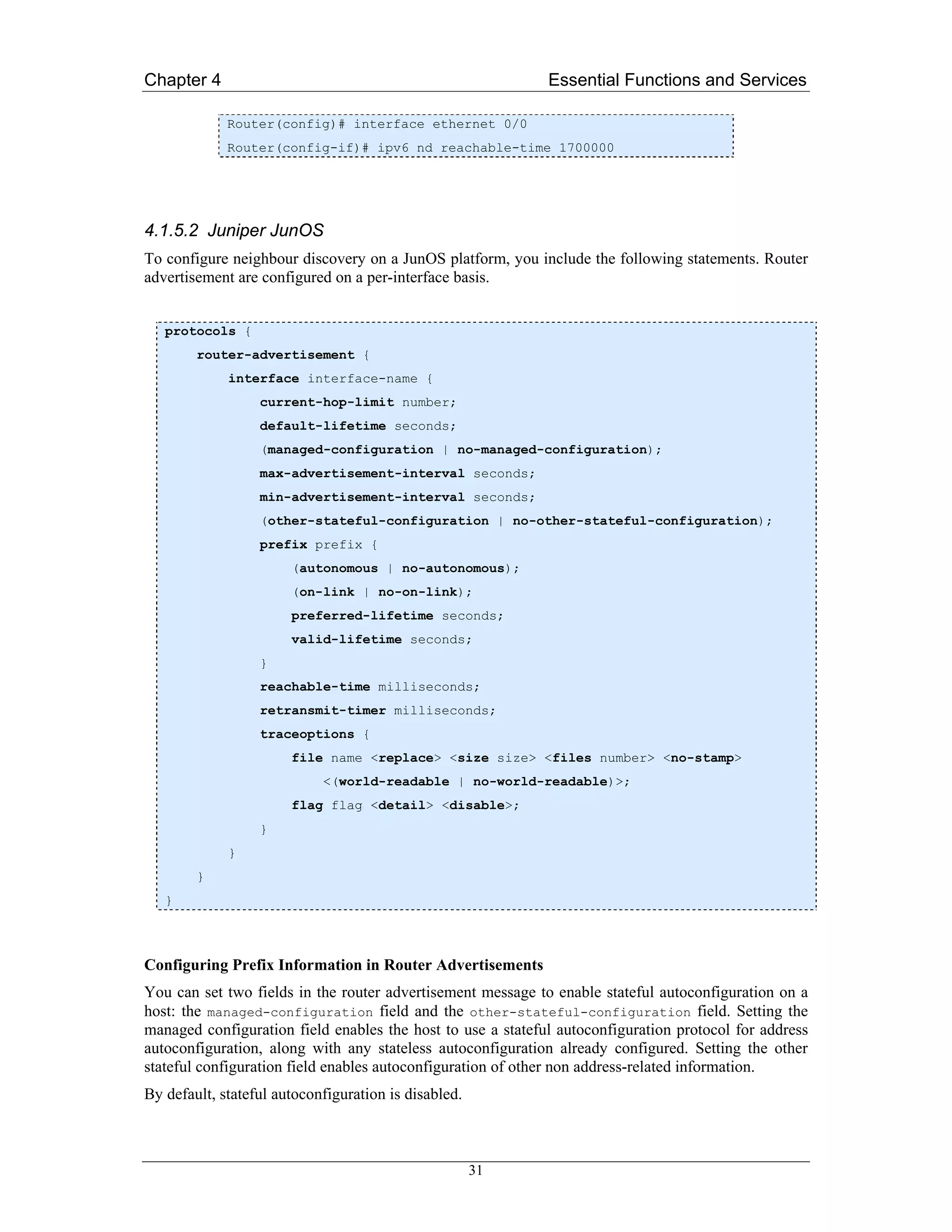
![Chapter 4 Essential Functions and Services
On-Link / Not On-Link
Router advertisement messages carry prefixes and information about them. A prefix is on-link when it
is assigned to an interface on a specified link. The prefixes specify whether they are on-link or not on-
link. A node considers a prefix to be on-link if it is represented by one of the link’s prefixes, a
neighboring router specifies the address as the target of a redirect message, a neighbor advertisement
message is received for the (target) address, or any neighbor discovery message is received from the
address. These prefixes are also used for address autoconfiguration. The information about the
prefixes specifies the lifetime of the prefixes, whether the prefix is autonomous, and whether the
prefix is on-link.
You can specify prefixes in the router advertisement messages as on-link. When set as on-link, the
prefixes are used for on-link determination. By default, prefixes are on-link.
To explicitly set prefixes as on-link or not on-link, include the on-link or no-on-link statement:
[edit protocols router-advertisement interface interface-name prefix prefix]
on-link | no-on-link;
Autonomous / Not Autonomous
You can specify prefixes in the router advertisement messages as autonomous. When set as
autonomous, the prefixes are used for stateless address autoconfiguration. By default, prefixes are
autonomous.
To explicitly specify prefixes as autonomous, include the autonomous or no-autonomous statement:
[edit protocols router-advertisement interface interface-name prefix prefix]
autonomous | no-autonomous;
Preferred Lifetime
The preferred lifetime for the prefixes in the router advertisement messages specifies how long the
prefix generated by stateless autoconfiguration remains preferred. By default, the preferred lifetime is
set to 604,800 seconds.
To configure the preferred lifetime, include the preferred-lifetime statement:
[edit protocols router-advertisement interface interface-name prefix prefix]
preferred-lifetime seconds;
If you set the preferred lifetime to 0xffffffff, the lifetime is infinite.
The preferred lifetime value must never exceed the valid lifetime value.
Valid Lifetime
The valid lifetime for the prefixes in the router advertisement messages specifies how long the prefix
remains valid for on-link determination. By default, the valid lifetime is set to 2,592,000 seconds.
To configure the valid lifetime, include the valid-lifetime statement:
[edit protocols router-advertisement interface interface-name prefix prefix]
valid-lifetime seconds;
32](https://image.slidesharecdn.com/ipv6deployment-guide-110112200202-phpapp01/75/IPv6-Deployment-Guide-46-2048.jpg)
![Chapter 4 Essential Functions and Services
If you set the valid lifetime to 0xffffffff, the lifetime is infinite.
The valid lifetime value must never be smaller than the preferred lifetime value.
Trace Options
To trace router advertisement traffic, you can specify options in the global traceoptions statement at
the [edit routing-options] hierarchy level, and you can specify router advertisement options by
including the traceoptions statement:
[edit protocols router-advertisement]
traceoptions {
file name <replace> <size size> <files number> <no-stamp>
<(world-readable | no-world-readable)>;
flag flag <flag-modifier> <disable>;
}
Note: Use the trace option flag detail with caution. These flags may cause the CPU to become very
busy.
Timing and Configuring Router Advertisements
Default Lifetime
The default lifetime in router advertisement messages indicates the lifetime associated with the default
router. To modify the default lifetime timer, include the default-lifetime statement:
[edit protocols router-advertisement interface interface-name]
default-lifetime seconds;
By default, the default router lifetime is three times the maximum advertisement interval.
Min/Max Advertisement Interval
The router sends router advertisements on each interface configured to transmit messages. The
advertisements include route information and indicate to network hosts that the router is operational.
The router sends these messages periodically, with a time range defined by minimum and maximum
values.
To modify the router advertisement interval, include the min-advertisement-interval and max-
advertisement-interval statements:
[edit protocols router-advertisement interface interface-name]
min-advertisement-interval seconds;
max-advertisement-interval seconds;
By default, the maximum advertisement interval is 600 seconds and the minimum advertisement
interval is one-third the maximum interval, or 200 seconds.
33](https://image.slidesharecdn.com/ipv6deployment-guide-110112200202-phpapp01/75/IPv6-Deployment-Guide-47-2048.jpg)
![Chapter 4 Essential Functions and Services
Reachable Time
After receiving a reachability confirmation from a neighbor, a node considers that neighbor reachable
for a certain amount of time without receiving another confirmation. This mechanism is used for
neighbor unreachability detection, a mechanism for finding link failures to a target node.
To modify the reachable time limit, include the reachable-time statement:
[edit protocols router-advertisement interface interface-name]
reachable-time milliseconds;
By default, the reachable time period is 0 milliseconds.
Current Hop Limit
The current-hop-limit field in the router advertisement messages indicates the default value placed
in the hop count field of the IP header for outgoing packets. To configure the hop limit, include the
current-hop-limit statement:
[edit protocols router-advertisement interface interface-name]
current-hop-limit number;
The default hop limit is 64.
4.1.5.3 Quagga
Quagga is an advanced routing software package that provides TCP/IP based routing protocols.
Information on Quagga in this book is based on the Quagga Manual for version 0.96. Quagga is
started as a fork of GNU Zebra and incorporates the Zebra protocol today as part of the suite.
Currently Quagga supports GNU/Linux, BSD and Solaris. Below is a list of OS versions on which
Quagga runs. Porting Quagga to other platforms is not so difficult. Platform dependent codes exist
only in the ZEBRA daemon. Protocol daemons are platform independent.
• GNU/Linux 2.0.37
• GNU/Linux 2.2.x and higher
• FreeBSD 2.2.8
• FreeBSD 3.x
• FreeBSD 4.x
• NetBSD 1.4
• OpenBSD 2.5
• Solaris 2.6
• Solaris 7
Some IPv6 stacks are in development. Quagga supports the following IPv6 stacks. For BSD, we
recommend KAME IPv6 stack. Solaris IPv6 stack is not yet supported.
• Linux IPv6 stack for GNU/Linux 2.2.x and higher.
• KAME IPv6 stack for BSD.
34](https://image.slidesharecdn.com/ipv6deployment-guide-110112200202-phpapp01/75/IPv6-Deployment-Guide-48-2048.jpg)
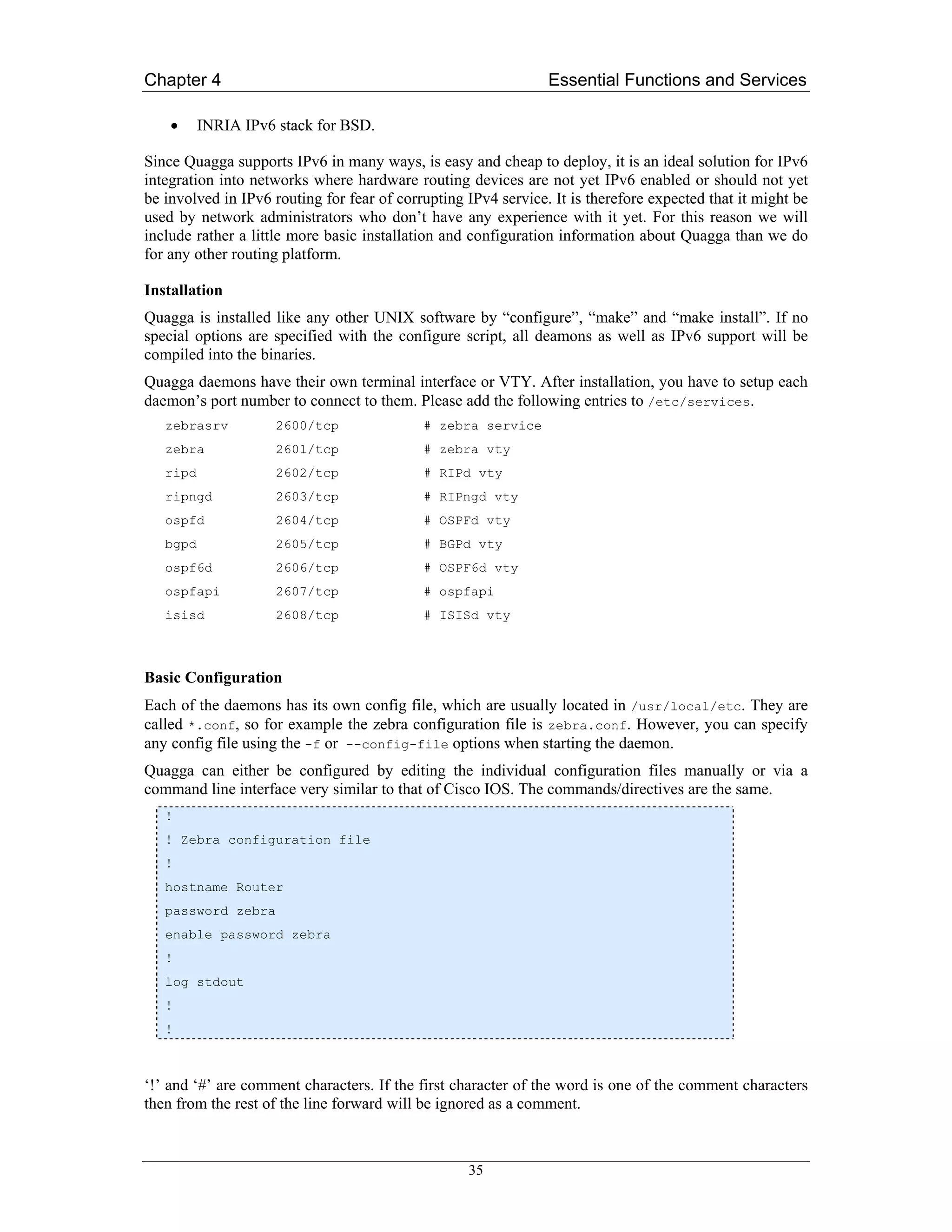
![Chapter 4 Essential Functions and Services
If a comment character is not the first character of the word, it’s a normal character. So in the
following example ‘!’ will not be regarded as a comment and the password is set to ‘zebra!password’.
password zebra!password
To configure Quagga/Zebra via the command line you can connect to the daemon using the telnet
protocol.
To enable a VTY interface, you have to setup a VTY password. If there is no VTY password, one
cannot connect to the VTY interface at all.
% telnet localhost 2601
Trying 127.0.0.1...
Connected to localhost.
Escape character is '^]'.
Hello, this is zebra (version 0.96)
Copyright 1997-2000 Kunihiro Ishiguro
User Access Verification
Password: XXXXX
Router> ?
enable Turn on privileged commands
exit Exit current mode and down to previous mode
help Description of the interactive help system
list Print command list
show Show running system information
who Display who is on a vty
Router> enable
Password: XXXXX
Router# configure terminal
Router(config)# interface eth0
Router(config-if)# ip address 10.0.0.1/8
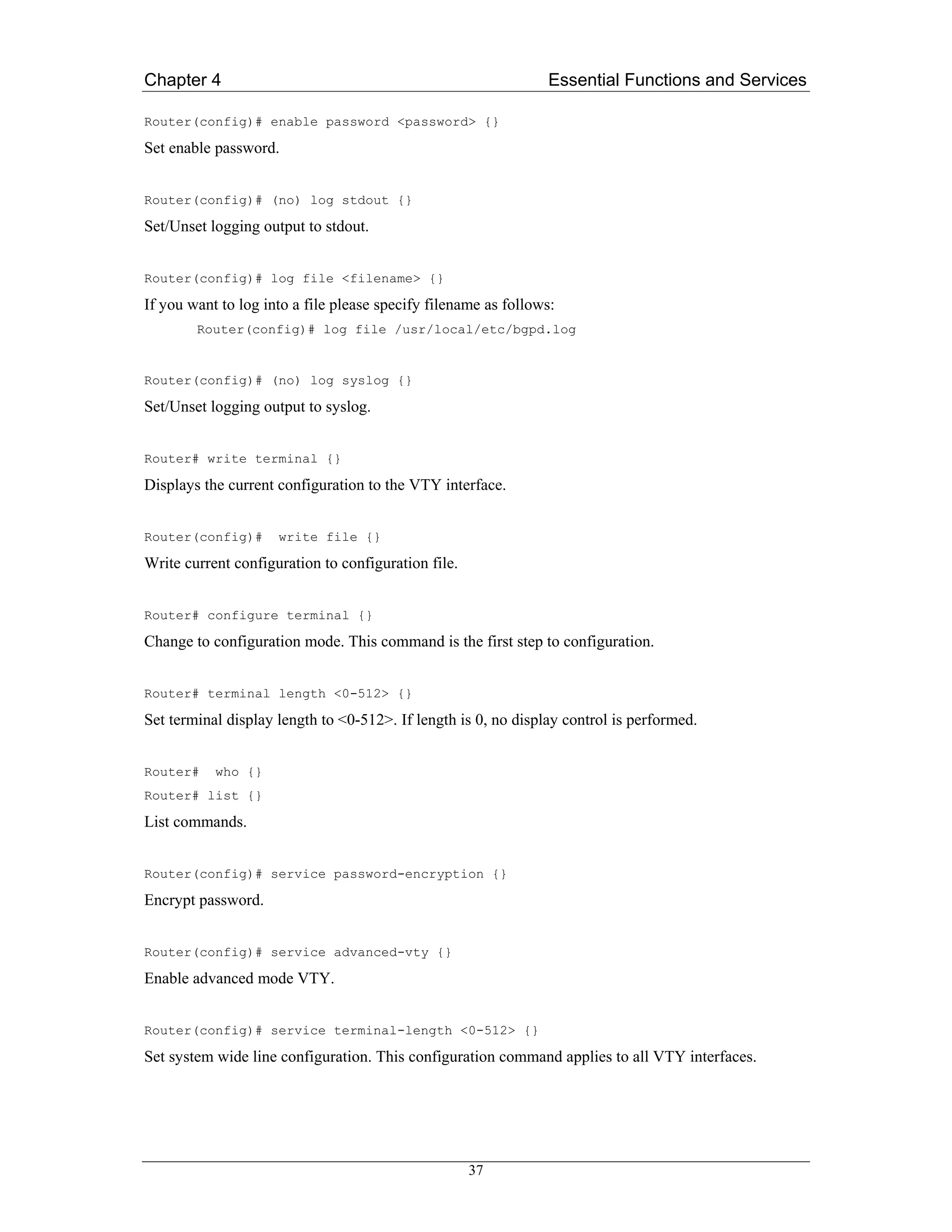
Basic Configuration Commands
Router(config)# hostname <hostname> {}
Set hostname of the router.
Router(config)# password <password> {}
Set password for VTY interface. If there is no password, a VTY won’t accept connections.
36](https://image.slidesharecdn.com/ipv6deployment-guide-110112200202-phpapp01/75/IPv6-Deployment-Guide-50-2048.jpg)
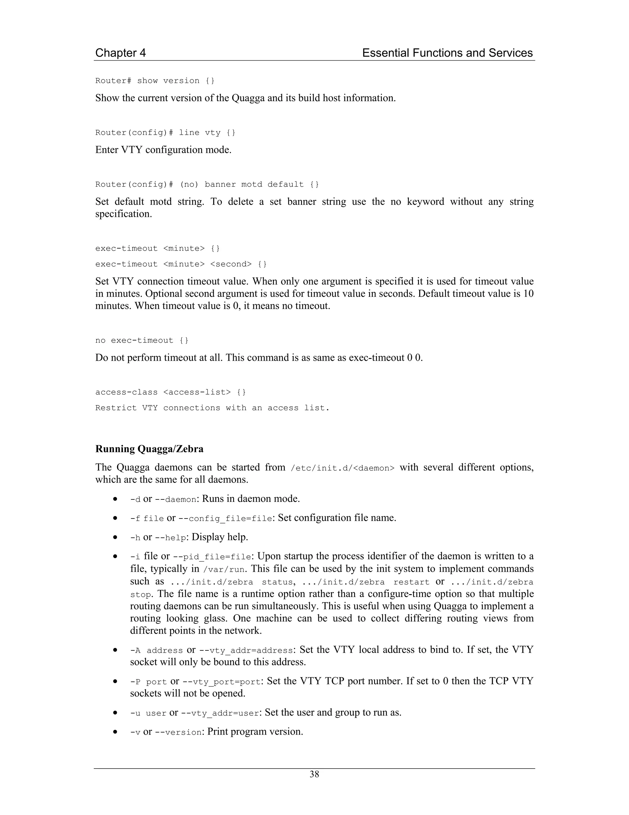
![Chapter 4 Essential Functions and Services
Besides the common invocation options, the Zebra itself has some specific options:
• -b or --batch: Runs in batch mode. Zebra parses configuration file and terminates
immediately.
• -k or --keep_kernel: When Zebra starts up, don’t delete old self inserted routes.
• -l or --log_mode: Set verbose logging on.
• -r or --retain: When program terminates, retain routes added by Zebra.
Configuring Router Advertisements and Neighbor Discovery
Router Advertisements are configured per interface, so the following commands have to be entered in
the context of an interface:
Command Syntax:
Router(config-if)# (no) ipv6 nd suppress-ra {}
Either switches off or on (no keyword) sending router advertisements on that interface.
Command Syntax:
Router(config-if)# (no) ipv6 nd prefix <ipv6prefix> [valid-lifetime]
[preferred-lifetime] [off-link] [no-autconfig] {}
This command configures the IPv6 prefix to include in router advertisements. Several prefix specific
optional parameters and flags may follow:
• valid-lifetime: The length of time in seconds during which the prefix is valid for the
purpose of on-link determination. Value infinite represents infinity (i.e. a value of all one bits
(0xffffffff)). Range: <0-4294967295> Default: 2592000
• preferred-lifetime: The length of time in seconds during what addresses generated from
the prefix remain preferred. Value infinite represents infinity. Range: <0-4294967295>
Default: 604800
• off-link: Indicates that advertisements makes no statement about on-link or off-link
properties of the prefix. Default: not set, i.e. this prefix can be used for on-link determination.
• no-autoconfig: Indicates to hosts on the local link that the specified prefix cannot be used for
IPv6 autoconfiguration. Default: not set, i.e. prefix can be used for autoconfiguration.
Command Syntax:
Router(config-if)# (no) ipv6 nd ra-interval <seconds> {}
The maximum time allowed between sending unsolicited multicast router advertisements from the
interface, in seconds. Must be no less than 3 seconds. The default is 600. Omit <seconds> to delete the
statement with the no keyword.
Command Syntax:
Router(config-if)# (no) ipv6 nd ra-lifetime <seconds> {}
This command sets the value to be placed in the Router Lifetime field of router advertisements sent
from the interface, in seconds. It indicates the usefulness of the router as a default router on this
39](https://image.slidesharecdn.com/ipv6deployment-guide-110112200202-phpapp01/75/IPv6-Deployment-Guide-53-2048.jpg)
![Chapter 4 Essential Functions and Services
While SURFNET has a professional environment in place to provide name services, maintaining both
the master and the slave name server within the same operational environment is not the optimal
solution.
Several other NRENS joined in to provide secondary name service (see Appendix A2). Those name
servers have to be accessible with IPv4 transport (for compatibility reasons) and IPv6 transport.
In due course GRNET requested participation in this effort. While it was not necessary, or even useful,
to have as many slave nameservers as NRENs involved, GRNET seemed to be a special case since
GRNET’s connection to the 6NET core was implemented as a tunnelled link. Thus it was proposed, at
least for the initial phase, to add a machine in GRNET as an additional slave server.
The basic (prototype) service for the domains 6net.org and sixnet.org supported the consortium’s
website, mailing lists, and - in due course - other infrastructure functions.
The initial configuration for 6net.org and sixnet.org is as follows:
$ dig 6net.org. soa
[ ... ]
;; ANSWER SECTION:
6net.org. 86400 IN SOA zesbot.ipv6.surfnet.nl. ipv6.surfnet.nl.
;; AUTHORITY SECTION:
6net.org. 86400 IN NS zesbot.ipv6.surfnet.nl.
6net.org. 86400 IN NS ns.ipv6.uni-muenster.de.
6net.org. 86400 IN NS foo.grnet.gr.
6net.org. 86400 IN NS ns3.surfnet.nl.
6net.org. 86400 IN NS scsnms.switch.ch.
;; ADDITIONAL SECTION:
foo.grnet.gr. 3035 IN A 194.177.210.211
foo.grnet.gr. 3035 IN AAAA 2001:648:0:1000:194:177:210:211
ns3.surfnet.nl. 85835 IN A 195.169.124.71
ns3.surfnet.nl. 85835 IN AAAA 2001:610:1:800b:a00:20ff:fe9a:16eb
scsnms.switch.ch. 85835 IN A 130.59.1.30
scsnms.switch.ch. 85835 IN A 130.59.10.30
scsnms.switch.ch. 254 IN AAAA 2001:620::1
zesbot.ipv6.surfnet.nl. 85835 IN A 192.87.110.60
zesbot.ipv6.surfnet.nl. 85835 IN AAAA 2001:610:508:110:2a0:c9ff:fedd:67e7
$ dig sixnet.org. soa
[ ... ]
;; ANSWER SECTION:
sixnet.org. 86400 IN SOA zesbot.ipv6.surfnet.nl. ipv6.surfnet.nl.
;; AUTHORITY SECTION:
sixnet.org. 86400 IN NS zesbot.ipv6.surfnet.nl.
sixnet.org. 86400 IN NS ns.ipv6.uni-muenster.de.
45](https://image.slidesharecdn.com/ipv6deployment-guide-110112200202-phpapp01/75/IPv6-Deployment-Guide-59-2048.jpg)
![Chapter 4 Essential Functions and Services
sixnet.org. 86400 IN NS foo.grnet.gr.
sixnet.org. 86400 IN NS ns3.surfnet.nl.
sixnet.org. 86400 IN NS scsnms.switch.ch.
;; ADDITIONAL SECTION:
ns3.surfnet.nl. 81287 IN A 195.169.124.71
ns3.surfnet.nl. 81287 IN AAAA 2001:610:1:800b:a00:20ff:fe9a:16eb
zesbot.ipv6.surfnet.nl. 86400 IN A 192.87.110.60
zesbot.ipv6.surfnet.nl. 86400 IN AAAA 2001:610:508:110:2a0:c9ff:fedd:67e7
Support functions for network operations
Based on the experience gained in TEN-34, TEN-155 and GÉANT, DANTE has developed a formal
naming scheme which encodes certain pieces of operational and management information into the
FQDNs which are used to refer to individual systems and/or to individual interfaces on a particular
system (router).
In particular, individual components of this naming system encode the country of a particular PoP
location, a particular router in a PoP, a particular interface and the link information to connect to a PoP
in a different country. As this system has proven to be very useful for such an environment (see the
output of a traceroute command in GÉANT), it has been adopted to also label the components used to
implement 6NET.
$ traceroute www.dante.org.uk
traceroute to www.dante.org.uk (193.63.211.4), 30 hops max, 38 byte packets
1 Wien1.ACO.net (192.153.174.1) 0.747 ms 0.203 ms 0.217 ms
2 aconet.at1.at.geant.net (62.40.103.1) 0.393 ms 0.419 ms 0.377 ms
3 at.ch1.ch.geant.net (62.40.96.2) 17.373 ms 17.341 ms 17.336 ms
4 ch.fr1.fr.geant.net (62.40.96.30) 26.064 ms 26.041 ms 26.039 ms
5 fr.uk1.uk.geant.net (62.40.96.90) 33.282 ms 33.303 ms 33.947 ms
6 janet-gw.uk1.uk.geant.net (62.40.103.150) 33.369 ms 33.238 ms 33.219 ms
[ ... ]
12 zeta.dante.org.uk (193.63.211.4) 43.012 ms 40.986 ms 41.417 ms
This system requires the creation (and delegation) of subdomains in 6net.org to support the proposed
naming structure. The well-defined (and well-known) ISO3166 2-letter country-codes are used to
denote individual PoP locations.
Many of those subdomains in 6net.org have already been delegated to DANTE to support the
development of the naming scheme for 6NET and the planning for the roll-out of the network. This
approach allows pre-configuration of entries for those components for which the technical details (and
the PoP location) have already been specified (by the end of March 2002).
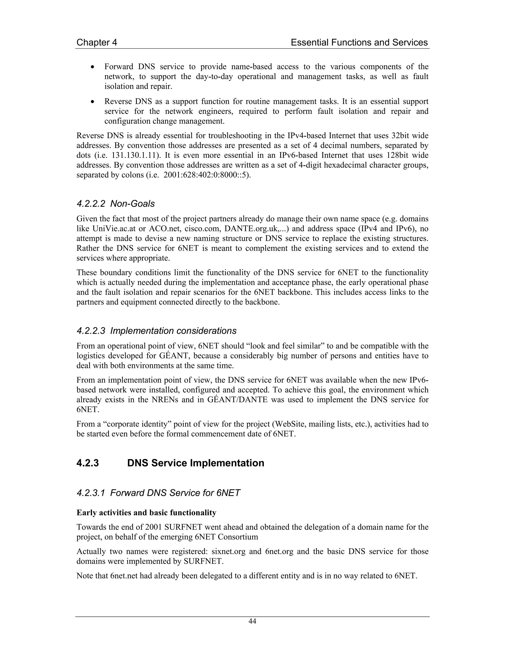
Here is an example of such an initial delegation:
> dig uk.6net.org soa
[…]
46](https://image.slidesharecdn.com/ipv6deployment-guide-110112200202-phpapp01/75/IPv6-Deployment-Guide-60-2048.jpg)
![Chapter 4 Essential Functions and Services
From a software technology perspective, no changes to the name server software in itself are required
in order to support the translation of literal IPv6 addresses into name strings. For both protocol
families the same basic mechanisms and the same RR type are used: the PTR record. But the rules to
convert a literal address to a lookup string are different!
IPv4 uses the decimal encoded external representation of an IPv4 address to build the lookup string,
e.g.
Working with
131.130.1.11
Leads to an attempt to find a PTR record for
11.1.130.131.in-addr.arpa.
But IPv6 uses a nibble-based hexadecimal digit encoding which generates a much longer lookup
string:
2001:610:508:110:2a0:c9ff:fedd:67e7 becomes
7.e.7.6.d.d.e.f.f.f.9.c.0.a.2.0.0.1.1.0.8.0.5.0.0.1.6.0.1.0.0.2.ip6.arpa.
However, much like in the forward DNS environment, the same issues apply for the transport
protocol(s). For legacy reasons IPv4 has still to be supported as the transport mechanism initially,
being extended to allow IPv6 as the transport mechanism as soon as possible.
In reality, obtaining a delegation, properly configuring the name service and using the services for the
IPv6 address to name translation is quite a bit more complicated:
• The strings that have to be maintained in the zone files are much longer than those for the
IPv4 world (see the previous example);
• As the sTLA allocations made by the RIRs under the “bootstrap procedures” are not aligned
on a nibble boundary , classless delegation mechanisms must be used to properly delegate the
reverse zones;
• Initially the sub tree ipv6.int. in the DNS namespace was used to refer to the “reverse DNS for
IPv6”. Alas, the “int.” TLD is reserved for organisations established under an international
treaty or multi-national agreement - which is not really appropriate for reverse DNS in the
IPv6 based Internet.
Efforts have already been started to move that support function back to the “arpa.” TLD - into the
ip6.arpa. subtree. This migration has already begun, but it is a complex and lengthy process because
the “knowledge” about the subtree in the namespace (required for the generation of the lookup label)
is hardcoded into the resolver libraries.
In 2004, the migration should be finished, thus we only consider the ip6.arpa subtree.
$ dig ip6.arpa soa
[ … ]
;; ANSWER SECTION:
ip6.arpa. 0 IN SOA dns1.icann.org.
hostmaster.icann.org. 2003080400 3600 1800 604800 10800
;; AUTHORITY SECTION:
ip6.arpa. 172800 IN NS ns.ripe.net.
ip6.arpa. 172800 IN NS ns.apnic.net.
ip6.arpa. 172800 IN NS ns.icann.org.
48](https://image.slidesharecdn.com/ipv6deployment-guide-110112200202-phpapp01/75/IPv6-Deployment-Guide-62-2048.jpg)
![Chapter 4 Essential Functions and Services
ip6.arpa. 172800 IN NS tinnie.arin.net.
;; ADDITIONAL SECTION:
ns.ripe.net. 101778 IN A 193.0.0.193
ns.icann.org. 65365 IN A 192.0.34.126
tinnie.arin.net. 2331 IN A 63.146.182.189
ns.ripe.net. 110559 IN AAAA 2001:610:240:0:53::193
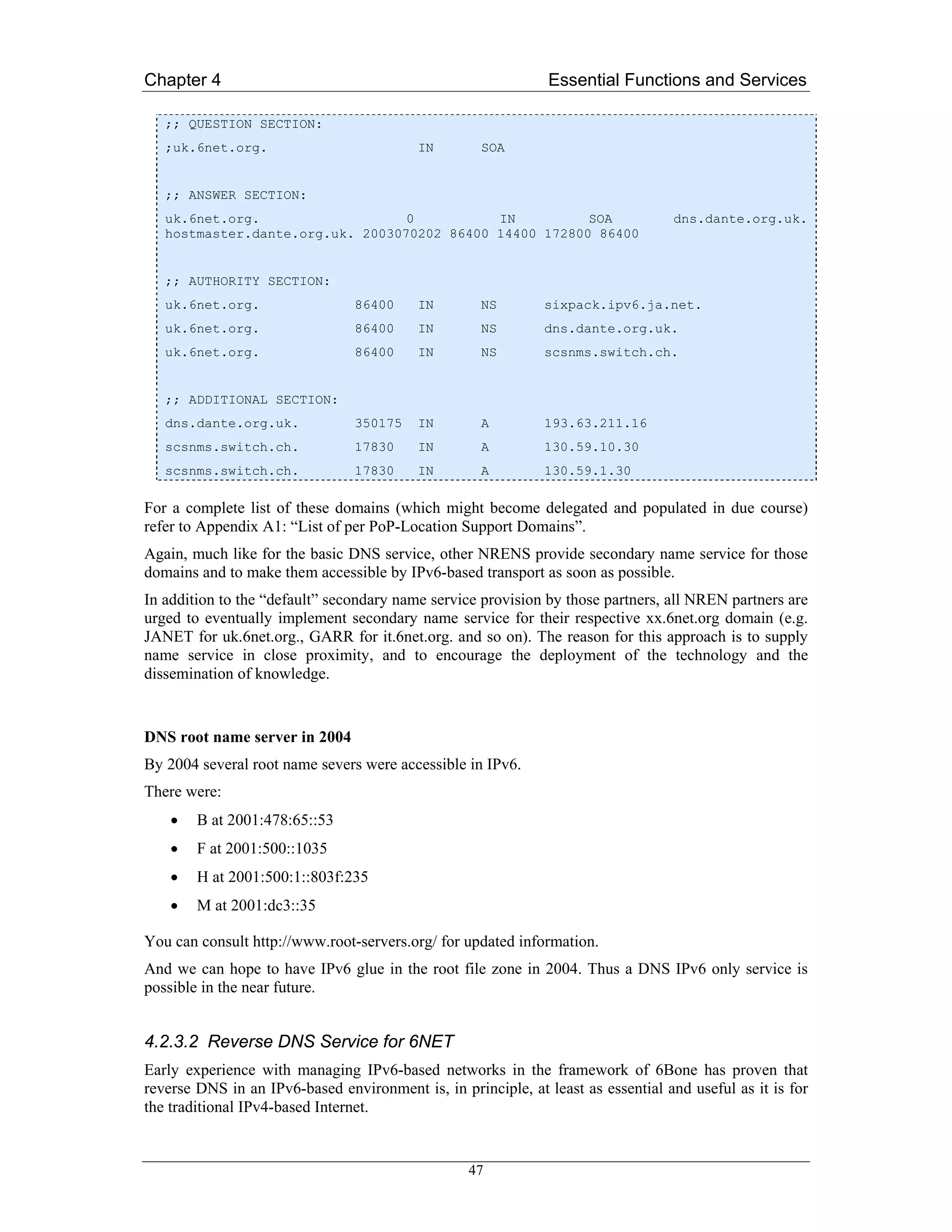
By the end of March 2002, none of the name servers for ip6.arpa. were accessible with IPv6 as the
transport protocol, but at least 3 of the name servers for ip6.int. seem to be IPv6-enabled.
In 2004, there is now one name server of ip6.arpa accessible in IPv6.
For a while implementing both reverse subtrees should be considered. How this is to be done can be
deducted from the following example which refers to the RIPE NCC’s address aggregate:
$ dig 7.0.1.0.0.2.ip6.arpa. soa
[ ... ]
;; QUESTION SECTION:
;7.0.1.0.0.2.ip6.arpa. IN SOA
;; ANSWER SECTION:
7.0.1.0.0.2.ip6.arpa. 0 IN SOA ns.ripe.net. ops.ripe.net.
2004020901 43200 7200 1209600 7200
;; AUTHORITY SECTION:
7.0.1.0.0.2.ip6.arpa. 431653 IN NS ns.ripe.net.
7.0.1.0.0.2.ip6.arpa. 431653 IN NS ns3.nic.fr.
7.0.1.0.0.2.ip6.arpa. 431653 IN NS sec1.apnic.net.
7.0.1.0.0.2.ip6.arpa. 431653 IN NS sec3.apnic.net.
7.0.1.0.0.2.ip6.arpa. 431653 IN NS sunic.sunet.se.
7.0.1.0.0.2.ip6.arpa. 431653 IN NS auth03.ns.uu.net.
7.0.1.0.0.2.ip6.arpa. 431653 IN NS tinnie.arin.net.
7.0.1.0.0.2.ip6.arpa. 431653 IN NS munnari.oz.au.
;; ADDITIONAL SECTION:
ns.ripe.net. 98853 IN A 193.0.0.193
ns3.nic.fr. 82089 IN A 192.134.0.49
sec1.apnic.net. 135878 IN A 202.12.29.59
sec3.apnic.net. 411 IN A 202.12.28.140
sunic.sunet.se. 82899 IN A 192.36.125.2
auth03.ns.uu.net. 51944 IN A 198.6.1.83
tinnie.arin.net. 10217 IN A 63.146.182.189
munnari.oz.au. 109009 IN A 128.250.22.2
munnari.oz.au. 109009 IN A 128.250.1.21
ns.ripe.net. 107633 IN AAAA 2001:610:240:0:53::193
49](https://image.slidesharecdn.com/ipv6deployment-guide-110112200202-phpapp01/75/IPv6-Deployment-Guide-63-2048.jpg)
![Chapter 4 Essential Functions and Services
• manual key roll-overs
More sophisticated key management functions may be implemented if the DNSSEC-specific
guidelines become available in time.
Note : there are two types of DNSSEC Key : zone-signing-key (ZSK) that signed all RR of the zone
and key-signing key (KSK) that signed only the KEY RR. Only the KSK is transmitted to the parent
zone. This permit to do an easier key rollover: you can change the ZSK without change the KSK.
In special case when there is only one Key: it’s a ZSK and this Key is transmitted to the parent zone.
4.2.3.4 Internationalizing Domain Names in Applications (IDNA)
IDNA is described in the RFC 3490 [RFC3490] and contains a mechanism called Internationalizing
Domain Names in Applications (IDNA). With IDNA, applications can use certain ASCII name labels
to represents non-ASCII name. IDNA doesn’t have impact on 6NET DNS structure. From RFC3490 :
“In particular, IDNA does not depend on any changes to DNS servers, resolvers, or protocol elements,
because the ASCII name service provided by the existing DNS is entirely sufficient for IDNA.”
Thus IDNA is transparent for the DNS transport.
51](https://image.slidesharecdn.com/ipv6deployment-guide-110112200202-phpapp01/75/IPv6-Deployment-Guide-65-2048.jpg)
![Chapter 4 Essential Functions and Services
4.3 DHCPv6
Despite the existence of stateless autoconfiguration for IPv6 (RFC 2462), there is still a need for
DHCP in IPv6. DHCP can be a complement to the stateless autoconfiguration where it can supply
hosts with DNS, NTP and other configuration data. DHCP can also take care of address allocations,
and replace stateless autoconfiguration completely.
Using the same address allocation system as DHCPv4 for IPv6 would mean that 264 addresses are
available per link. Thus a stripped down “lightweight” version of DHCPv6 (stateless DHCPv6) was
also developed but this is in fact a different protocol to DHCPv6. However, it is based on DHCPv6 in
order to save design and implementation time.
4.3.1 Using DHCP Together With Stateless Autoconfiguration
A typical host will need to configure at least IP addresses and a recursive DNS server address in order
to be used. The major problem of the current stateless autoconfiguration, is that it does not supply a
DNS server address. The DNS server address might be a bit more stable, but it’s still a problem to find
and configure the correct address. People have suggested various techniques for configuring this,
DHCP being but one of them (the others included multicasting and anycasting).
DHCP was assessed as a good solution, since a client might also need other configuration data like
domain search path, NTP servers etc. Some have claimed that DHCP is too complex, but a DHCP
server in an environment with stateless autoconfiguration does not need to support IP address
delegations, and does not need any per-client state. There are also other features that could be omitted
in a DHCP server if necessary. Also note that even if the client has an address from stateless
autoconfiguration, it might wish to request additional addresses from DHCP, some possible reasons
are described in the next section.
4.3.2 Using DHCP Instead of Stateless Autoconfiguration
In this case we not only wish to configure DNS etc. as described in previous section, but also IP
addresses. There are several reasons one might want to do this. Stateless autoconfiguration as
described in RFC 2462 creates addresses based on interface identifiers that are typically EUI-64
identifiers. On e.g. Ethernet this will be created from the MAC address on the hosts Ethernet interface.
This means that the IPv6 address will depend on the physical Ethernet interface. One might wish for a
host to have a stable address independent of which Ethernet interface is used though, and there are also
some privacy concerns. It can also be a pain to have meaningful PTR records in the DNS for reverse
lookups. DHCP can help to fulfill all of these requirements.
4.3.3 Overview of the Standardisation of DHCPv6
Several years ago, the IETF took on the initiative to develop a version of DHCP for IPv6 (DHCPv6).
The specification became a Dynamic Host Configuration working group (DHC WG) work item and
has been under development in that working group since the initiative was started.
There are a couple of reasons for the long development and approval process for DHCPv6. While
DHCPv6 is similar to DHCPv4 [RFC2131], [RFC2132] in its goals and scope, all of the details of the
protocol operation are different. For example, because the configuration of an interface with multiple
IPv6 addresses is a fundamental feature of IPv6, DHCPv6 can manage the assignment of multiple
addresses, potentially assigned over a period of time. In contrast, DHCPv4 can only assign a single
address to an interface. Dhcpv6 also addresses several deficiencies in the DHCPv4 protocol, including
the operation of relay agents and security.
52](https://image.slidesharecdn.com/ipv6deployment-guide-110112200202-phpapp01/75/IPv6-Deployment-Guide-66-2048.jpg)
![Chapter 4 Essential Functions and Services
Another reason for the long development period for DHCPv6 is that there has been some debate in the
IETF about the utility and role for DHCPv6, so the specification has been tracking a moving target.
There have been many significant changes to the DHCPv6 specification in the revisions of the
DHCPv6 Internet-Draft. Implementations of earlier drafts will not interoperate with the final
specification as documented in RFC 3315 [RFC3315].
One question about the use of DHCPv6 is the specification of stateless address autoconfiguration. For
IPv4, the primary use of DHCP is the assignment of IP addresses to hosts. In IPv6, a host can use
stateless address autoconfiguration to obtain its IPv6 addresses independent of any server-based
address assignment mechanism. However, a host that has used stateless address autoconfiguration may
still require additional configuration information, such as a list of addresses for DNS servers. Thus,
“Stateless DHCPv6”, specified in RFC 3736 [RFC3736], is used to provide these additional
configuration parameters.
4.3.3.1 DHCPv6 Options
DHCPv6 uses “options” in the variable format section of a DHCPv6message. Several options,
necessary for the operation of the protocol, are defined in section 22 of the DHCPv6 specification
(RFC 3315). Several other options have been in development and are described in the remainder of
this section.
IPv6 Prefix Options for DHCPv6
The “Prefix Option” is used for prefix delegation in DHCPv6. An ISP uses prefix delegation to
configure a CPE device (typically a router) with one or more prefixes to use in the customer’s
network. This option is specified in RFC 3633 [RFC3633].
DSTM Options for DHCPv6
There are three dual-stack transition mechanism (DSTM) [Bou05], options for DHCPv6. The first two
options are used to assign IPv4 addresses to a host using DSTM and to give the address of a DSTM
tunnel endpoint. These options are documented in [RB05]
DSTM Ports Option for DHCPv6
The third option DSTM DHCPv6 specifies the ports to be used by a host for IPv4-mapped IPv6
addresses, and is documented in [Shi05]. The progress of all three DSTM options will be synchronized
with the progress of the DSTM specification through the IETF.
DNS Configuration options for DHCPv6
There are two DNS configuration options documented in RFC 3646 [RFC3646]. The first passes the
IP addresses of a list of DNS servers to a host. The second option passes a list of domains to be used
as a domain search list by the host.
NIS/NIS+ Configuration Options for DHCPv6
There are four DHCPv6 options for NIS and NIS+ configuration, which are documented in
[RFC3898]. Two of the options provide a list of NIS servers and an NIS domain to a host, and two
options provide a list of NIS+ servers and an NIS+ domain.
Time Configuration Options for DHCPv6
There are two DHCPv6 options for time configuration. One option provides a list of NTP servers to
the host and is described in RFC 4075 [RFC4075]. The other option provides time zone information to
the host and is currently specified by the Internet Draft draft-ietf-dhc-dhcpv6-opt-tz-00 [Kal03].
53](https://image.slidesharecdn.com/ipv6deployment-guide-110112200202-phpapp01/75/IPv6-Deployment-Guide-67-2048.jpg)
![Chapter 4 Essential Functions and Services
Client Preferred Prefix option for DHCPv6
The client preferred prefix option allows a client to indicate the prefixes form which it would prefer to
have its addresses assigned. This option is documented in [Vij03], and is still under discussion by the
DHC WG.
Load Balancing for DHCPv6
DHCPv6 provides for the operation of multiple servers. Under normal circumstances, all servers
respond to each request for service and the requesting client picks a server for service. The Internet
Draft “Load Balancing for DHCPv6” [Vol02] describes a mechanism through which multiple
cooperating DHCPv6 servers can determine which server should respond to a specific client. The
DHCPv6 load balancing mechanism was submitted to the IESG for approval as a Proposed Standard
in January 2003.
4.3.3.2 Guide About the Stateless DHCPv6 server
The DHCPv6 service of providing configuration information without address assignment is called
“stateless DHCPv6”, because the DHCPv6 server need not maintain any dynamic state about
individual clients while providing the service. Stateless DHCPv6 requires only a subset of the
DHCPv6 protocol and is significantly easier to implement and deploy. It is anticipated that stateless
DHCPv6 will be the primary way in which DHCPv6 is used in IPv6 networks.
Stateless DHCPv6 may be provided through centralized DHCPv6 servers, similar to the deployment of
DHCPv4 service. Because stateless DHCPv6 is a relatively simple protocol, it may be provided by a
CPE router, using, for example, DNS configuration information configured by the CPE administrator
or obtained through DHCPv6 from the ISP. Stateless DHCPv6 service may also be provided by DNS
servers, which would respond directly to hosts with DNS configuration information.
The requirements for implementing stateless DHCPv6 are documented in draft-droms-dhcpv6-
stateless-guide [Dro02]. This Internet Draft lists the messages and services that must be implemented
in servers and hosts to provide stateless DHCPv6 service.
4.3.4 Overview of the DHCPv6 Specifications
The architecture and message exchanges in DHCPv6 are similar to DHCPv4. A DHCPv6 client
initiates a DHCPv6 transaction by first locating a DHCPv6 server, and then making a request for
configuration information from that server. As in DHCPv4, an IPv6 address is assigned to a host with
a lease, and the host can initiate a transaction with the DHCPv6 server to extend the lease on an
address.
A DHCPv6 client uses a link-local address when exchanging messages with a DHCPv6 server. To
avoid the requirement that a DHCPv6 server be attached to every link, DHCPv6 relay agents forward
DHCPv6 messages between hosts and off-link servers. The mechanism through which relay agents
forward DHCPv6 messages allows for the use of multiple relay agents between a host and a server.
Relay agent options, through which a relay agent can provide additional information to the DHCPv6
server, are included as a design feature in the base DHCPv6 specification.
The address assignment mechanism in DHCPv6 allows for the assignment of multiple addresses to an
interface, and allows for the dynamic assignment of additional addresses over time. Addresses are
assigned to a host with a lease, a preferred lifetime and a valid lifetime. The mechanism can support
renumbering through the assignment of new addresses whose lifetimes overlap existing addresses to
allow for graceful transition. Addresses are grouped together for management into an “identity
association”, which the host and server exchange for address assignment. DHCPv6 can also be used
for assignment of temporary addresses [RFC3041].
54](https://image.slidesharecdn.com/ipv6deployment-guide-110112200202-phpapp01/75/IPv6-Deployment-Guide-68-2048.jpg)
![Chapter 4 Essential Functions and Services
Each DHCPv6 host has a “DHCP Unique Identifier” (DUID), which remains unchanged throughout
the lifetime of the host. Servers use this DUID to identify hosts reliably even if the host roam between
links.
Security is included in the DHCPv6 base specification. The security mechanism uses a framework
similar to the security mechanism for DHCPv4 defined in RFC 3118 [RFC3118]. In addition, security
for messages exchanged between relay agents and servers is provided by the use of IPSec.
A DHCPv6 server can trigger a message exchange with a host through the Reconfigure message.
Security is included for the Reconfigure message to prevent intruder attacks against DHCPv6 clients.
Stateless DHCPv6 uses a two-message exchange between a client and a server. To obtain
configuration information without address assignment through stateless DHCPv6, the host sends an
Information-request message. The DHCPv6 server responds with the requested configuration
information. The DHCPv6 server can be configured with host-specific configuration, to allow for
customized configuration of different classes of hosts. Stateless DHCPv6 service requires only a
subset of the mechanism and messages of the full DHCPv6 protocol, and is easier to implement and
deploy.
An ISP wishing to delegate a prefix or prefixes to a customer can use the prefix delegation option. To
use prefix delegation, the CPE initiates a DHCPv6 transaction with the ISP edge router. The ISP router
selects the prefix or prefixes to be assigned to the customer, through the ISP’s policy or customer
provisioning process, and returns those prefixes to the CPE. The prefixes are then available for use in
the customer’s network. For example, the customer may be assigned a /48 prefix, which is delegated
to the CPE through DHCPv6 prefix delegation. The CPE can then assign /64 prefixes from the
delegated /48 prefix to links in the customer’s network.
4.3.4.1 Differences between DHCP for IPv4 and IPv6
There are many differences, since DHCP IPv6 is a completely new protocol. We only list some of the
more obvious differences here.
• Hosts always have a link local address that can be used in requests (in IPv4 0.0.0.0 is used as
source address)
• Uses special multicast addresses for relay agents and servers
• No compatibility with BOOTP, since no BOOTP support on IPv6.
• Simplified two-message exchange for simple configuration cases
• A client can request multiple IPv6 addresses
• Client can send multiple unrelated requests to the same or different servers
• There is a reconfigure message where servers can tell clients to reconfigure. This feature is
optional.
4.3.5 DHCPv6 Implementations Overview
We found in general, that because of significant changes throughout the lifetime of the DHCPv6
specification, only the most recent implementations will likely be close to compatible with the final
specification.
After some investigation we found the implementations listed below. We only make a brief
description of each implementation. A test report of the DHCP implementations used in 6NET is
available in Deliverable 3.2.3 [D3.2.3].
55](https://image.slidesharecdn.com/ipv6deployment-guide-110112200202-phpapp01/75/IPv6-Deployment-Guide-69-2048.jpg)
![Chapter 4 Essential Functions and Services
HPUX DHCPv6 supports the following features:
• IPv6 address allocation
• Multiple IP addresses for an interface
• Reconfiguration messages
• Relay mechanism
• Request for configuration parameters from different servers within the same domain
• DNS server address
• DNS suffix
• NTP server address
• NIS domain name
• NIS server address
• NIS+ client domain name
• NIS+ server address
• SLP DA address and its scope
• SLP service scope
• Timezone
• IPv6 address allocation
• New message types
• Multiple IP addresses for an interface
• Reconfiguration messages
• Relay mechanism
• Request for configuration parameters from different servers within the same domain
It seems to be the most complete implementation at the time of writing.
7. Motorola implementation
This implementation is targeted to Linux to test address delegation of DHCPv6.
8. Cisco DHCPv6 in the IOS
The Cisco DHCPv6 implementation is part of IOS, and runs in Cisco routers. It is based on the -28
revision of the DHCPv6 specification (which has been accepted by the IESG as a Proposed Standard),
the prefix delegation RFC 3633 [RFC3633] and the DNS configuration options RFC 3646 [RFC3646].
The Cisco DHCPv6 client and server are specifically intended as a prefix delegation solution and do
not implement the entire DHCPv6 protocol. At present, Cisco’s DHCPv6 implements prefix
delegation, the rapid-commit mechanism, stateless DHCPv6 (“DHCPv6-lite”) and the following
options:
• Client Identifier option
• Server Identifier option
• Option Request option
• Preference option
57](https://image.slidesharecdn.com/ipv6deployment-guide-110112200202-phpapp01/75/IPv6-Deployment-Guide-71-2048.jpg)
![Chapter 5 Integration and Transition
Chapter 5
Integration and Transition
In this chapter we look at the problem of IPv6 integration and transition with existing IPv6 networks.
Expanding IPv6 functionality from a small infrastructure to a large site network can be a complex and
difficult venture. But if it is planned effectively, the deployment can be done in a phased and
controlled manner that maximises the chances of a smooth service introduction. For a large site there
are a lot of different requirements, and different conditions which make it necessary to employ various
transition mechanisms according to the peculiarities of, for example, a given subnet, wireless or
mobile environment or dial-in technology. In this chapter we explain which potential options and
techniques exist to integrate IPv6 into a site network, which solution is appropriate for any special
kind of network infrastructure and of course how exactly one has to set up and configure these
techniques. Where possible, we also point to existing (current) problems and interoperability issues,
for example in running IPv4 and IPv6 in parallel or having IPv6-only hosts which still need to be able
to communicate with IPv4-only hosts on occasion. Numerous transitioning mechanisms and
procedures are described including tunnelling methods such as IPv6-in-IPv4 tunnelling, Tunnel
Brokers, ISATAP, 6to4, Teredo and translation methods such as NAT-PT, SIIT, SOCKS, ALGs and
Bump-in-the-Stack/API.
An overview of security issues in transition is available as an Internet Draft that was originally
produced as a result of 6NET experience [DKS05]. The security issues of individual transition
mechanisms are discussed in Chapter 9.
5.1 Problem Statement
With an IPv6 host or local network configured, getting connectivity to the global IPv6 Internet is vital
if you wish to communicate with other IPv6 systems. Today, this is usually accomplished either
natively or, more commonly, with an IPv6-in-IPv4 tunnelling technique using either manual or
automatic tunnel configuration methods.
The academic participants of the 6NET project are mostly fortunate enough to have native
connectivity to their National Research and Education Networks (NRENs) and from there to a globally
connected native IPv6 network (spanning GÉANT, and links to Abilene in the US and WIDE in
Japan). Other sites may not be so lucky; for them a tunnelling mechanism is the only realistic option
for IPv6 connectivity.
IPv6-only deployments are rare, especially in Europe, but are an interesting exercise with a view to the
end game of IPv6 deployment. However, the practical reality is that sites deploying IPv6 will not
transition to IPv6-only, but transition to a state where they support both IPv4 and IPv6 (dual-stack).
The dual-stack environment then allows IPv6-only devices to be introduced, as a site slowly phases
out IPv4. For this reason, translation mechanisms between IPv4 and IPv6 systems are less frequently
59](https://image.slidesharecdn.com/ipv6deployment-guide-110112200202-phpapp01/75/IPv6-Deployment-Guide-73-2048.jpg)
![Chapter 5 Integration and Transition
required; however we discuss transition mechanisms, from viewpoints of the network, transport and
application layers at which translation may be applied.
IPv6 can be introduced to a site in three basic ways, categorized into how connectivity of each system
to the IPv6 Internet is achieved and how the network and hosts themselves have to be enhanced to
make IPv6 possible. We call these categories “dual stack”, “additional IPv6 infrastructure” (which
generally involves IPv6-in-IPv4 tunnelling) and “IPv6-only networking”. In a large-scale network one
will never only use one technique or another. It is much more likely that the best way for getting
systems connected within a site has to be decided for each subnet or even each host anew, which leads
to the deployment of many different techniques according to the different demands and peculiarities of
a certain part of the network. This chapter focuses on the theoretical description of each of the three
general transition scenarios “dual stack”, “additional IPv6 infrastructure” and “IPv6-only networks”.
Descriptions of special transition mechanisms as they come into place within those scenarios are
included in the next chapter.
Once the internal networking is determined, the next step is to arrange external connectivity for the
whole site, which involves external routing issues and is really only possible either natively or via
some tunnelling mechanism. With IPv6, the choice of an external connectivity method will determine
the IPv6 addressing prefix within the site. A site prefix is usually (as recommended by the RIRs) a /48
prefix, which allows 16 bits of subnet address space for the /64 subnets.
5.1.1 Dual Stack
One of the conceptually easiest ways of introducing IPv6 to a network is called the “dual stack
mechanism”, as described in [NG05], which is an update of RFC 2893 [RFC2893]. Using this method
a host or a router is equipped with both IPv4 and IPv6 protocol stacks in the operating system (though
this may typically be implemented in a hybrid way). Each such node, called an “IPv4/IPv6 node”, is
configured with both IPv4 and IPv6 addresses. It can therefore both send and receive datagrams
belonging to both protocols and thus communicate with every node in the IPv4 and IPv6 network.
This is the simplest and most desirable way for IPv4 and IPv6 to coexist and is most likely to be the
next step in a network’s evolution in general, before a wider transition to an IPv6-only Internet can be
achieved worldwide (in the long term future).
There are no real transition mechanisms to use within the dual stack scenario, as “Dual Stack” is a
method to integrate IPv6 itself.
One challenge in deploying an IPv6/IPv4 Dual Stack network lies in configuring both internal and
external routing for both protocols. If one has for example used OSPFv2 for intra site routing before
adding IPv6 to the Layer 3 network one will either have to transition to a protocol, which is both IPv4
and IPv6-capable like IS-IS or be forced run one IS-IS or OSPFv3 in addition to OSPFv2. Since
configuring IPv6 routing in a dual stack network is usually completely independent from the
configuration of IPv4 routing the reader can refer to Chapter 6 for most of the issues concerning basic
routing setup.
Another challenge lies in the interaction of the two protocols, and how this interaction is managed,
given that a dual-stack network will (in an early stage of worldwide IPv6 deployment) generally be
interacting with IPv4 external networks. An example is the deployment of email servers for SMTP,
and how the MX servers are provisioned for both protocols by offering IPv4 or IPv6 reachability, and
how failover is handled between the protocols.
60](https://image.slidesharecdn.com/ipv6deployment-guide-110112200202-phpapp01/75/IPv6-Deployment-Guide-74-2048.jpg)
![Chapter 5 Integration and Transition
5.2 Tunnelling Methods
In this section we describe methods for carrying IPv6 over existing IPv4 networks, which invariably
means using some kind of tunnelling mechanism, either manually or automatically configured.
5.2.1 Configured Tunnels
Configured tunnelling is defined in the update to RFC 2893 [NG05] as IPv6-over-IPv4 tunnelling
where the IPv4 tunnel’s endpoint address is determined by configuration information on the
encapsulating node. Therefore the encapsulating node must keep information about all the tunnel
endpoint addresses. These kinds of tunnels are point-to-point and need to be configured manually. For
control of the tunnel paths, and to reduce the potential for tunnel relay denial-of-service attacks,
manually configured tunnels can be advantageous over automatically configured tunnels.
Configured tunnels are best employed when providing external IPv6 connectivity to a whole network.
There are not yet many providers who offer IPv6 in any way but if one has the possibility to get initial
IPv6 connectivity from an already IPv6-connected site, one of the easiest, most stable and secure ways
to get the IPv6 traffic routed to the (as yet) unconnected site is via an IPv6-in-IPv4 tunnel. One can
even set up a BGP peering on that link, although if the tunnel is the only off-site link, BGP is not
required unless the connecting site is interested in seeing the BGP routing information of its upstream
provider. Usually static routes meet the requirements.
Within a site, configured IPv6-in-IPv4 tunnels can also be used if there is a part of the network that
cannot (for whatever reason) be natively connected to the rest of the IPv6 topology. Since these kinds
of tunnels have to be configured by hand this only makes sense if there is a requirement for just a few
of those tunnels. There is no point in connecting a lot of different isolated hosts or subnets by a
manually configured tunnel. There are other tunnelling methods specifically designed for this purpose,
such as tunnel brokers, 6to4, Teredo or ISATAP (see below for more details on those). In sites that
support IEEE 802.1q VLAN Layer 2 mechanisms, the VLANs can be used to carry IPv6 traffic
between disparate subnets in the site, as described in [Cho04b].
Note that IPv6-in-IPv4 tunnels may be used for OSPFv3 routing but not with IS-IS as IS-IS is based
on Layer 2 while IPv6-in-IPv4 tunnels are completely Layer 3. For IS-IS to work over a tunnelled link
generic encapsulation (GRE tunnels [RFC2784]) can be used.
5.2.2 Tunnel Broker
Instead of manually configuring each tunnel endpoint it is possible to use executable scripts instead.
This “automatic” alternative is called a “tunnel broker” and is presented in RFC 3053 [RFC3053].
Like manually configured tunnels, the tunnel broker is useful where a user has a dual-stack host in an
IPv4-only network, and wishes to gain IPv6 connectivity. The basic philosophy of a tunnel broker is
that it allows a user to connect to a web server, (optionally) enter some authentication details, and
receive back a short script to run and establish an IPv6-in-IPv4 tunnel to the tunnel broker server.
The operation of a typical tunnel broker service is illustrated in Figure 5-1. The provider of a tunnel
broker service needs to provide a web server available over IPv4 and a dual stack router capable of
accepting automated setup commands to create new tunnels to client endpoints. It is possible that both
functions can be served from one machine.
62](https://image.slidesharecdn.com/ipv6deployment-guide-110112200202-phpapp01/75/IPv6-Deployment-Guide-76-2048.jpg)
![Chapter 5 Integration and Transition
IPv6 networks 1
User connects to web server
Tunnel broker requesting tunnel
tunnel server
2 2
3 Web server returns script to create
tunnel to the tunnel server, and
Tunnel broker informs tunnel server of new client
1 Web server
3
Client activates script, and gaining
Dual-stack host access to IPv6 networks via the
tunnel server
Figure 5-1 Tunnel broker components and setup procedure
A tunnel broker can be implemented in many ways and is not constrained to IPv6-in-IPv4 tunnels.
Layer 2 or GRE tunnels may be used as well. The requirement for the service is that it needs to keep
track of the tunnels created and whom they belong to. Ideally it should have some authentication to
grant access to the service, but in practice early implementations have not required this. The Freenet6
service (http://www.freenet6.net) is perhaps best known, but being based in Canada is not ideal for use
in European networks (the first hop to any destination would be thousands of miles away). SixXS
(http://www.sixxs.com) is another example more suitable and available in Europe; ideally any ISP
should offer local tunnel broker facilities for its users, if no native IPv6 service is present.
Tunnel brokers can serve subnet tunnels, as well as single host tunnels. In the former case the host
obtaining the tunnel is in reality a router, and the mechanism for obtaining the tunnel can be more
generic (using for example TSP, the tunnel setup protocol [BP05]), and may need specific functions to
activate or deactivate the tunnel.
The tunnel broker service is generally easy to use for the client, but there are some concerns about the
deployment of server systems, e.g. in security of access, and in reallocation of tunnels where clients
use dynamic IPv4 addresses (as is typical behind commodity dialup). If using standard IPv6-in-IPv4
tunnelling, any intervening firewall must pass Protocol 41 to/from the tunnel server. Doing so, and
without further control of the tunnelled traffic, a site administrator may be blissfully unaware of users
on their site who use tunnel brokers, thus not creating any site demand for “proper” IPv6 deployment
and possibly creating security holes which the administrator does not know about and therefore does
not guard against.
Some tunnel broker implementations will handle clients with dynamically changing IPv4 addresses or
that are behind IPv4 NATs. Such features are often highly desirable. Heartbeat features are often used
for the former problem, while [BP05] offers a solution for the latter, negotiating a UDP-based
encapsulation method that can work through a NAT. Use of TSP will need the client to run a special
client however.
A tunnel broker is an important transition aid; it enables easy-to-use IPv6 network access, and we see
a number of supported brokers used in the 6NET environment during the project. The tunnel brokers
may be deployed by sites (universities) or by NRENs (as not every university will wish to run its own
broker). If no broker is available to a national participant, remote brokers may be used, but doing so
63](https://image.slidesharecdn.com/ipv6deployment-guide-110112200202-phpapp01/75/IPv6-Deployment-Guide-77-2048.jpg)
![Chapter 5 Integration and Transition
will naturally reduce the efficiency of the tunnelling, since the first IPv6 hop for the client will be in
the (distant) remote network, even if the target is relatively local.
5.2.3 Automatic Tunnels
This type of tunnel mechanism has been one of the first to be developed and has since then mostly
been replaced by more sophisticated mechanisms. It uses IPv4-compatible IPv6 addresses on the
tunnel endpoints. The address of the recipient node is specified by the packet that is being
encapsulated. This method can only be used on router-to-host and host-to-host communication since
these are the only schemes where one tunnel endpoint is also the recipient. Due to the use of particular
addresses it only works on IPv6 over IPv4 tunnelling and not vice versa.
Such automatic tunnelling has now been deprecated, and has been written out of the [NG05] update.
One reason for that lies in the ad-hoc nature of connectivity that results, lacking structure in the IPv6
domain; solutions such as ISATAP or 6to4 (see below) are generally considered preferable. The
authors of this book strongly advise not to use this technique anymore, even where implementations
still exist.
5.2.4 6to4
The transition mechanism known as 6to4 [RFC3056] is a form of automatic router-to-router tunnelling
that uses the IANA-assigned IPv6 prefix 2002::/16 to designate a site that participates in 6to4. It
allows isolated IPv6 domains to communicate with other IPv6 domains with minimal configuration.
An isolated IPv6 site will assign itself a prefix of 2002:V4ADDR::/48, where V4ADDR is the globally
unique IPv4 address configured on the appropriate interface of the domain’s egress router (see Figure
5-2). This prefix has exactly the same format as normal /48 prefixes and thus allows an IPv6 domain
to use it like any other valid /48 prefix. In the scenario where 6to4 domains wish to communicate with
other 6to4 domains, no tunnel configuration is needed. Tunnel endpoints are determined by the value
of the global routing prefix of the IPv6 destination address contained in the IPv6 packet being
transmitted, which includes the IPv4 address. In this scenario, an arbitrary number of 6to4 domains
may communicate without the need for any tunnel configuration. Furthermore, the 6to4 routers do not
need to run any exterior IPv6 routing protocol as IPv4 exterior routing performs the task instead.
2002:C251:2E01::/48 2002:C253:6A06::/48
194.81.46.1 194.83.106.6
6-to-4 6-to-4 IPv4 6-to-4 6-to-4
Domain Router Cloud Router Domain
IPv6 host
IPv6 host IPv6 over IPv4 Tunnel
Figure 5-2 6to4 Service Overview
64](https://image.slidesharecdn.com/ipv6deployment-guide-110112200202-phpapp01/75/IPv6-Deployment-Guide-78-2048.jpg)
![Chapter 5 Integration and Transition
When 6to4 domains wish to communicate with non-6to4 IPv6 domains however, the situation is a
little more complex. In this case, connectivity between the domains is achieved via a relay router,
which is essentially a router that has at least one logical 6to4 interface and at least one native IPv6
interface. Unlike with the previous scenario, IPv6 exterior routing must be used. The relay router
advertises the 6to4 2002::/16 prefix into the native IPv6 routing domain. In addition the relay router
may advertise native IPv6 routes into its 6to4 connection. The relay router can be discovered using
IPv4 anycast, as described in RFC 3068 [RFC3068].
Most ISPs/NRENs only advertise their 6to4 relay within their own network. There are very few
“public” relays, in part due to the security concerns described below. Despite such concerns, and
concerns over provision of multicast over 6to4, the protocol does offer a very convenient, automatic
way for an IPv4 site to gain IPv6 connectivity.
The general use of 6to4 is as a mechanism for an IPv6 site border router with only IPv4 external
connectivity to establish automatic connectivity to the IPv6 public Internet. Other methods (e.g.
ISATAP or native IPv6 networking if available) can then be used inside the site. It can also be used on
a host, but such usage is (we expect) rather less common and not originally intended.
5.2.5 6over4
6over4 is defined in RFC 2529 [RFC2529]. It interconnects isolated IPv6 hosts in a site through IPv6-
in-IPv4 encapsulation without explicit tunnels. It uses IPv4 addresses as interface identifiers and
creates a virtual link using an IPv4 multicast group with organization-local scope. IPv6 multicast
addresses are mapped to IPv4 multicast addresses to allow neighbour discovery. The 6over4 method
has fallen out of favour due to a number of reasons, including the general lack of IPv4 multicast
support in site/ISP networks.
There have been a small number of implementations, including those by 3Com and Cisco, but
practically no adoption. We thus do not consider 6over in any detail, as the method seems (in effect)
deprecated. We would thus not recommend its use.
5.2.6 ISATAP
An alternative to 6over4 is ISATAP (Intra-Site Automatic Tunnel Addressing Protocol) [TGTT05].
ISATAP also uses the site’s IPv4 infrastructure as a virtual link, but it does not use IPv4 multicast, so
the link is NBMA (Non-Broadcast Multiple Access).
ISATAP, like 6over4, creates an interface identifier based on the interface’s IPv4 address. ISATAP
supports both autoconfiguration and manual configuration of addresses, but the IPv4 address of the
interface will be embedded as the last 32 bits of the IPv6 addresses. As with 6over4, the IPv4-address
needs only be unique in the network the service is deployed in.
Usually multicast is used for neighbour discovery operations like address resolution and router
solicitations or advertisements. Since the IPv4 address is always embedded in the IPv6 address,
address resolution is trivial. For router solicitations to work, the host must somehow have learned of
IPv4 addresses of possible ISATAP routers (through DHCP, DNS, TEP, manual configuration etc.),
and will then send solicitations as unicast. The router always sends advertisements as unicast and only
as a reply to a host’s solicitation. Each ISATAP host will regularly send solicitations to the ISATAP
routers it knows of.
ISATAP has been implemented on some platforms, e.g. Windows XP and IOS, although it has been
removed from USAGI Linux now. The authors feel that while it has applicability in some sites, where
65](https://image.slidesharecdn.com/ipv6deployment-guide-110112200202-phpapp01/75/IPv6-Deployment-Guide-79-2048.jpg)
![Chapter 5 Integration and Transition
a phased, managed introduction of IPv6 is desired, an approach like [Cho04b] is preferable. In either
case, the solution is an interim step until dual-stack network elements are available for the site.
5.2.7 Teredo
The Teredo transitioning mechanism [Hui05], is a form of automatic tunnelling intended to provide
IPv6 connectivity to IPv4 hosts that are located behind a NAT [RFC1613] and therefore do not
possess permanent, global-scope IPv4 addresses. It is a host-to-host automatic tunnelling mechanism
that provides IPv6 connectivity, when dual-stack hosts are located behind one ore multiple NATs by
encapsulating IPv6 packets in IPv4-based User Datagram Protocol (UDP) messages.
As illustrated in Figure 5-3, the Teredo service employs two entities, a Teredo server and a Teredo
relay, in order to provide IPv6 connectivity to Teredo clients located behind a NAT. Unlike other
tunnelling mechanisms, Teredo encapsulates IPv6 packets in UDP (instead of directly over IPv4). A
well-known UDP port (3544) is used by the Teredo server to listen for requests from the Teredo
clients. Teredo addresses have the following structure:
Table 5-1 The Teredo Address Structure
32 bits 32 bits 16 bits 16 bits 32 bits
Teredo Prefix IPv4 Address of Flags Mapped Client UDP Port Mapped Client IPv4
Teredo Server Address
Figure 5-3 Teredo Infrastructure and Components
66](https://image.slidesharecdn.com/ipv6deployment-guide-110112200202-phpapp01/75/IPv6-Deployment-Guide-80-2048.jpg)
![Chapter 5 Integration and Transition
Both the “mapped client UDP port” and the “mapped client IPv4 address” are obfuscated; each bit in
the address and port number is reversed. Note that IPv6 addressing rules specify that for all unicast
addresses, Interface IDs are required to be 64 bits except those that begin with binary value 000.
Hence the flags field has to be encoded to conform to this requirement (see [Hui05] for more details).
The Teredo server listens for requests from Teredo clients, responding with an IPv6 address for them
to use. The Teredo server forwards the IPv4-encapsulated IPv6 packets sent from Teredo clients to the
Teredo relay. The server also forwards IPv6 packets received from the Teredo relay, that are destined
for a Teredo client, to the appropriate IPv4 address and UDP port of the client. The Teredo relay thus
acts as an IPv6 router and forwards IPv6 packets destined for Teredo clients to the Teredo server from
the IPv6 Internet and forwards IPv6 packets received from the Teredo server to the IPv6 Internet. The
Teredo relay also advertises the reachability of the Teredo service into the IPv6 Internet. It is likely
that the Teredo server and relay entities would be co-located as shown in Figure 5-3.
Analysing the Teredo IPv6 address format it becomes evident that the Teredo specification makes
rather inefficient use of the IPv6 address space with respect to the injection of routing prefixes. This is
because the Teredo relay must advertise the reachability of the Teredo service to the rest of the IPv6
Internet. The 32-bit Teredo prefix is common to all Teredo servers, so the relay must advertise IPv6
prefixes consisting of at least the Teredo prefix plus the IPv4 address of the Teredo server. This means
that routing prefixes for every distinct Teredo server must be injected into the IPv6 Internet. In theory,
this could mean injecting a routing prefixe into the IPv6 Internet for every IPv4 site that employs
NAT.
As such, the Teredo service should only be used as a ‘last resort’ where direct IPv6 connectivity or co-
locating a 6to4 router with the NAT is not possible. Furthermore, the Teredo method is complex, and
cannot be guaranteed to work across all NATs due in part to variations in NAT implementations.
5.2.8 Tunnel Setup Protocol
The Tunnel Setup Protocol (TSP) [BP05] is a general method designed to simplify the setup of
(authenticated) IPv6 tunnels over IPv4 networks. The TSP method was initially applied to tunnel
brokers, but the scope of the TSP applicability is much wider. As the name implies TSP is less of a
transition mechanism itself than a protocol to describe the proper (automatic) setup of any kind of
tunnel to transport IPv6 via a part of the network, where IPv6 is not available.
TSP offers advantages for tunnel brokers, including better support for IPv4 NAT traversal and support
for authentication of the tunnel setup.
5.2.9 Dual Stack Transition Mechanism (DSTM)
DSTM (Dual Stack Transition Mechanism) [Bou05] is a tunnelling solution for IPv6-only networks,
where IPv4 applications are still needed on dual-stack hosts within an IPv6-only infrastructure. IPv4
traffic is tunnelled over the IPv6-only domain until it reaches an IPv6/IPv4 gateway, which is in
charge of packet encapsulation/decapsulation and forwarding between the IPv6-only and IPv4-only
domains. The solution proposed by DSTM is transparent to any type of IPv4 application and allows
the use of layer 3 security.
Usually with a tunnelling scheme, one IPv4 address is required for every host wishing to connect to
the IPv4 Internet. DSTM reduces this constraint by dynamically allocating addresses only for the
duration of the communication making it possible for several hosts to share the same address on a
large time scale.
67](https://image.slidesharecdn.com/ipv6deployment-guide-110112200202-phpapp01/75/IPv6-Deployment-Guide-81-2048.jpg)
![Chapter 5 Integration and Transition
DSTM can be implemented if a network infrastructure only supports IPv6, but some of the nodes on
the network have dual-stack capability (and make use of IPv4-only applications). DSTM consists of
three components:
1. a DSTM server,
2. a DSTM gateway or TEP (Tunnel End Point) and
3. a dual-stack host (called a “DSTM client”) wishing to communicate using IPv4.
For the sake of simplicity, we have decided to present the server and the gateway as different
equipment, but in actual deployments, these two functionalities are co-located on the same equipment.
Figure 5-4 presents the interaction between these three elements.
Figure 5-4 DSTM Architecture
As long as communications can take place in native IPv6, none of the capacities of DSTM are
required. This applies to protocols like HTTP or SMTP, where the use of ALGs (Application Level
Gateways) is to be preferred. When a DSTM node detects the need of an IPv4 address by a query to
the DNS resulting in an IPv4 destination address or an application opening an IPv4 socket, the DSTM
process is launched.
When the first IPv4 packet needs to be sent, the DSTM client asks the server for an address (step 1 in
Figure 5-4). A number of protocols (DHCPv6 [RFC3315], TSP [BP02], RPC) have already been
proposed to perform this task. Native IPv6 transport is the only restriction in this matter. DSTM
developers are currently discussing whether a single method can be agreed for all DSTM
implementations.
Following an address request, the server asks the DSTM gateway to add a Tunnel End Point (TEP) for
the requesting DSTM client. It is the server who controls the IPv4/IPv6 address mapping performed at
the DSTM gateway. Initial versions of DSTM considered that the gateway would build its IPv6/IPv4
mapping table dynamically by observing packet headers, but this approach is now obsolete due to
security concerns.
If the end point for the new tunnel is successfully created, following the answering message from the
gateway, the DSTM server (who manages an IPv4 address pool) replies to the host with the following
information (step 2):
• The allocated IPv4 address,
• The period over which the address has been allocated
68](https://image.slidesharecdn.com/ipv6deployment-guide-110112200202-phpapp01/75/IPv6-Deployment-Guide-82-2048.jpg)
![Chapter 5 Integration and Transition
• IPv4 and IPv6 addresses of the TEP.
This information is used by the client to configure an IPv4-over-IPv6 tunnel towards the DSTM
gateway (step 3). At this point, the DSTM client has IPv4 connectivity and, if it obtained a global IPv4
address, it will be able to connect to any external IPv4 host.
In DSTM, the period of allocation can be configured based on address availability. Clients are
required to ask for allocation renewal before allocation time expires. Depending on local policy and
client behaviour, the DSTM server may accept or deny extending the allocation. In normal operation,
requests for allocation renewal are periodically sent until the address is no longer needed by the client.
As long as the address allocation is extended, the DSTM server is not required to update the IPv4/IPv6
mapping table at the gateway. However, when the allocation expires, the gateway must be informed in
order to update its tables and to allow other clients to reuse the TEP for the freed IPv4 address.
The DSTM gateway is in charge of packet forwarding between the IPv6-only domain and IPv4
networks. It performs packet encapsulation/decapsulation using an IPv4/IPv6 mapping table. For
successful bi-directional communication, it is very important to allow IPv4 forwarding at the gateway
and to make sure that, for any IPv4 packet coming from the outside, the route to the DSTM client
points to the TEP.
DSTM should be used in a network domain where IPv6 routing is enabled and ALL nodes within that
domain are able to communicate using IPv6. In this case, IPv4 support can be turned off. Thus the
burden of maintaining an IPv4 addressing plan and supporting IPv4 routing is removed. However,
given the huge number of IPv4-only hosts and applications in the Internet, a number of hosts inside
IPv6-only domains will still require IPv4 connectivity.
DSTM can be deployed where no other solutions, such as ALGs, can be implemented. DSTM allows
dual-stack nodes to obtain an IPv4 address and offers a default route (through an IPv4-in-IPv6 tunnel)
to an IPv4 gateway. Any IPv4-only application can run over an IPv6-only network if such a scheme is
used and, if DSTM is configured to allocate Global IPv4 addresses, hosts inside that domain will be
able to communicate with any other host on the Internet.
DSTM may be deployed in several phases. As a first step, IPv4 connectivity may be assured by
manually configuring tunnels from dual-stack nodes to a Tunnel End Point (TEP). In a second phase,
when address allocation or tunnel set up protocols become available (DHCPv6, TSP), it would be
possible to dynamically assign an IPv4 address to nodes which need one. In this phase, the address
may be allocated for the whole lifetime of the requesting node, reducing the complexity of address
management. Finally, when IPv4 address availability becomes a problem, DSTM may be configured
to allocate addresses only for small periods of time, based on the real needs of requesting hosts.
Since the address allocation process in DSTM is triggered only when IPv4 connectivity is strictly
necessary, the size of the IPv4 address pool required by the mechanism should decrease with time (as
more hosts and applications become IPv6 aware). However, if the lack of IPv4 address space
continues, DSTM may be extended to include the ‘ports option’ [Shi05], allowing simultaneous use of
the same address by several hosts, but increasing complexity.
5.2.9.1 The VPN Scenario
An alternative use of DSTM concerns what has been called “the VPN scenario” [RMT02]. It
concentrates on the situation where a DSTM node is outside its home domain. Supposing that the node
can easily obtain an IPv6 address on the visited network but no IPv4 configuration is possible, the
DSTM node can negotiate with its home DSTM server and TEP for IPv4 connectivity. If
authentication succeeds and the nomad node obtains an address, the node’s IPv4 traffic will be sent to
the TEP at its home network using an IPv4-in-IPv6 tunnel. Even if the path is not optimal, the node
obtains access to private IPv4 resources in its home domain and may obtain global IPv4 connectivity.
69](https://image.slidesharecdn.com/ipv6deployment-guide-110112200202-phpapp01/75/IPv6-Deployment-Guide-83-2048.jpg)
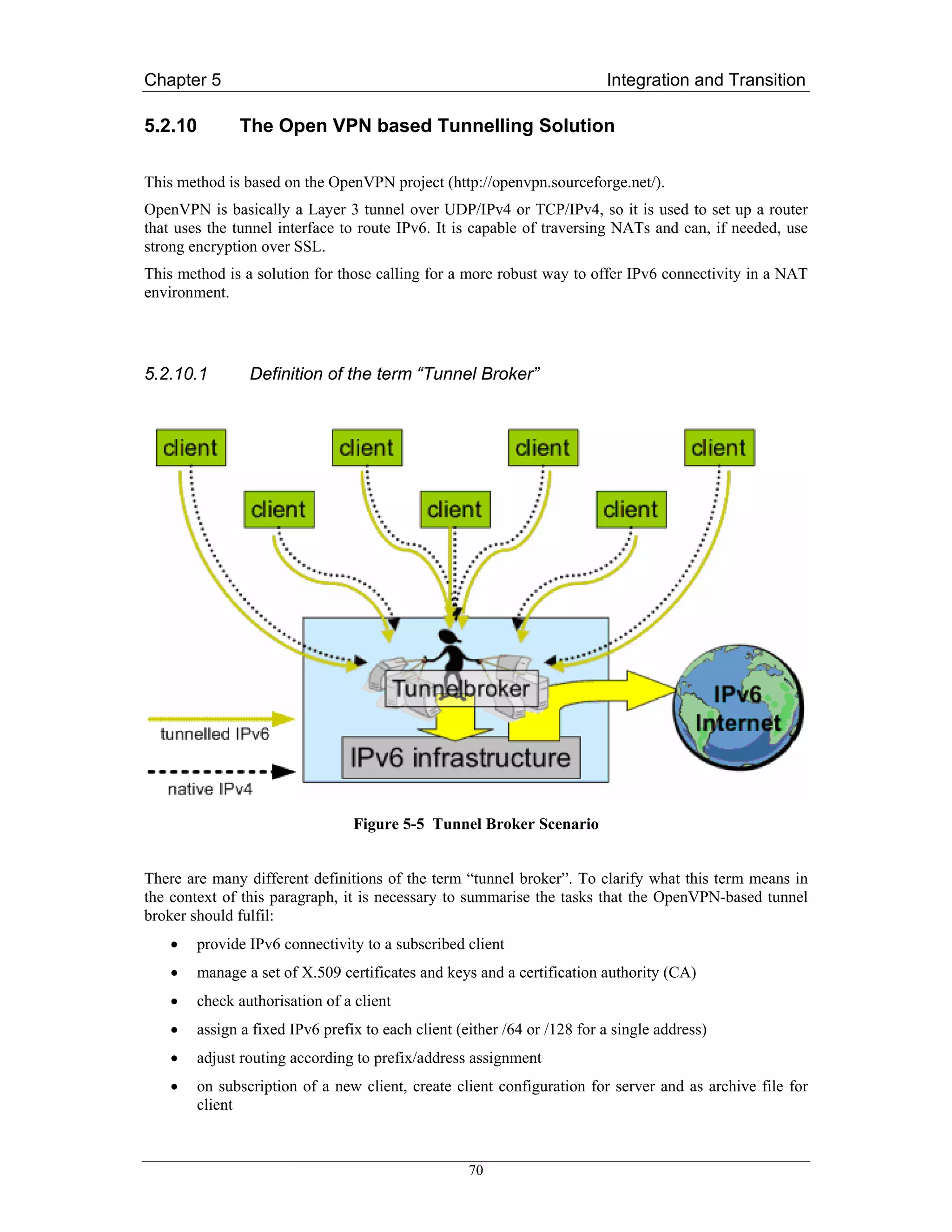
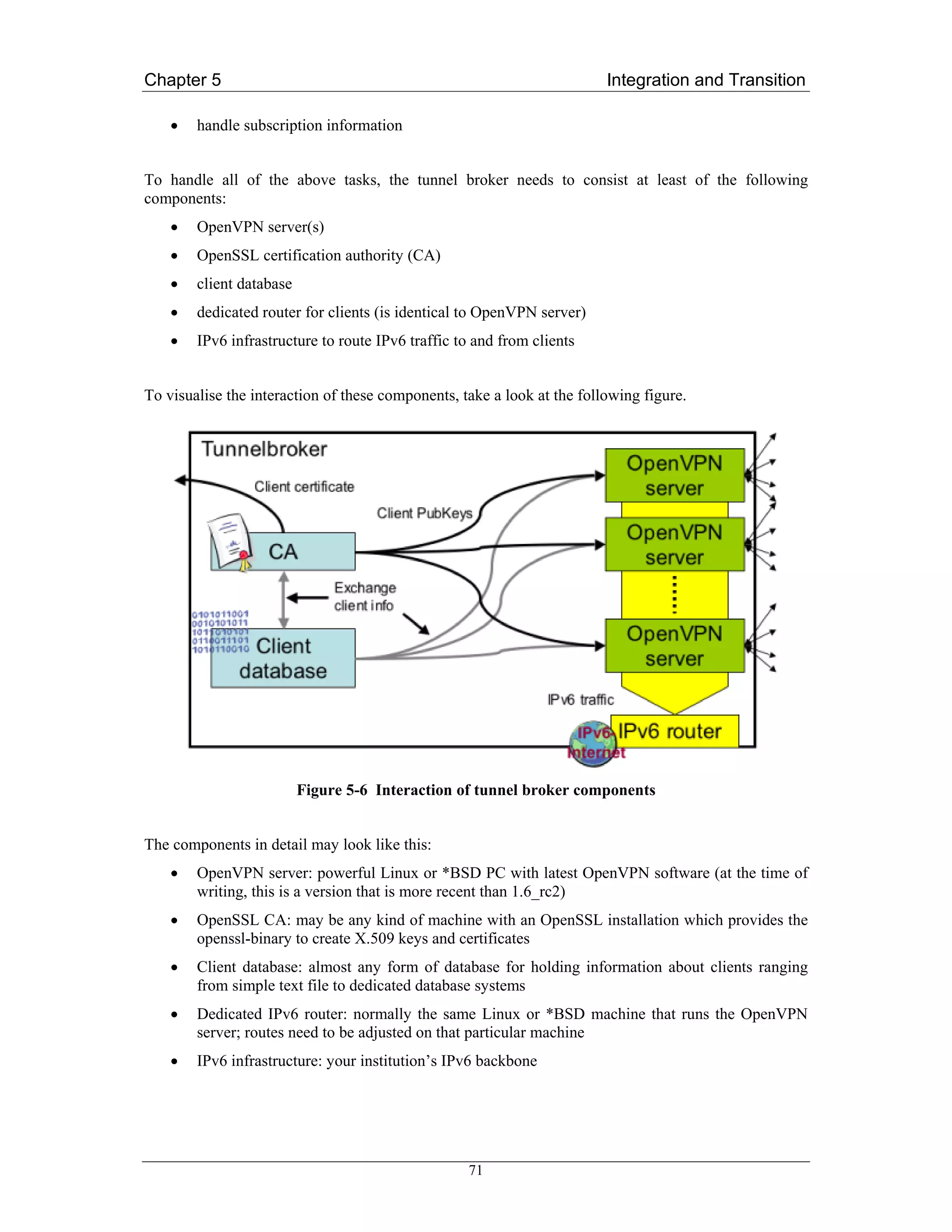
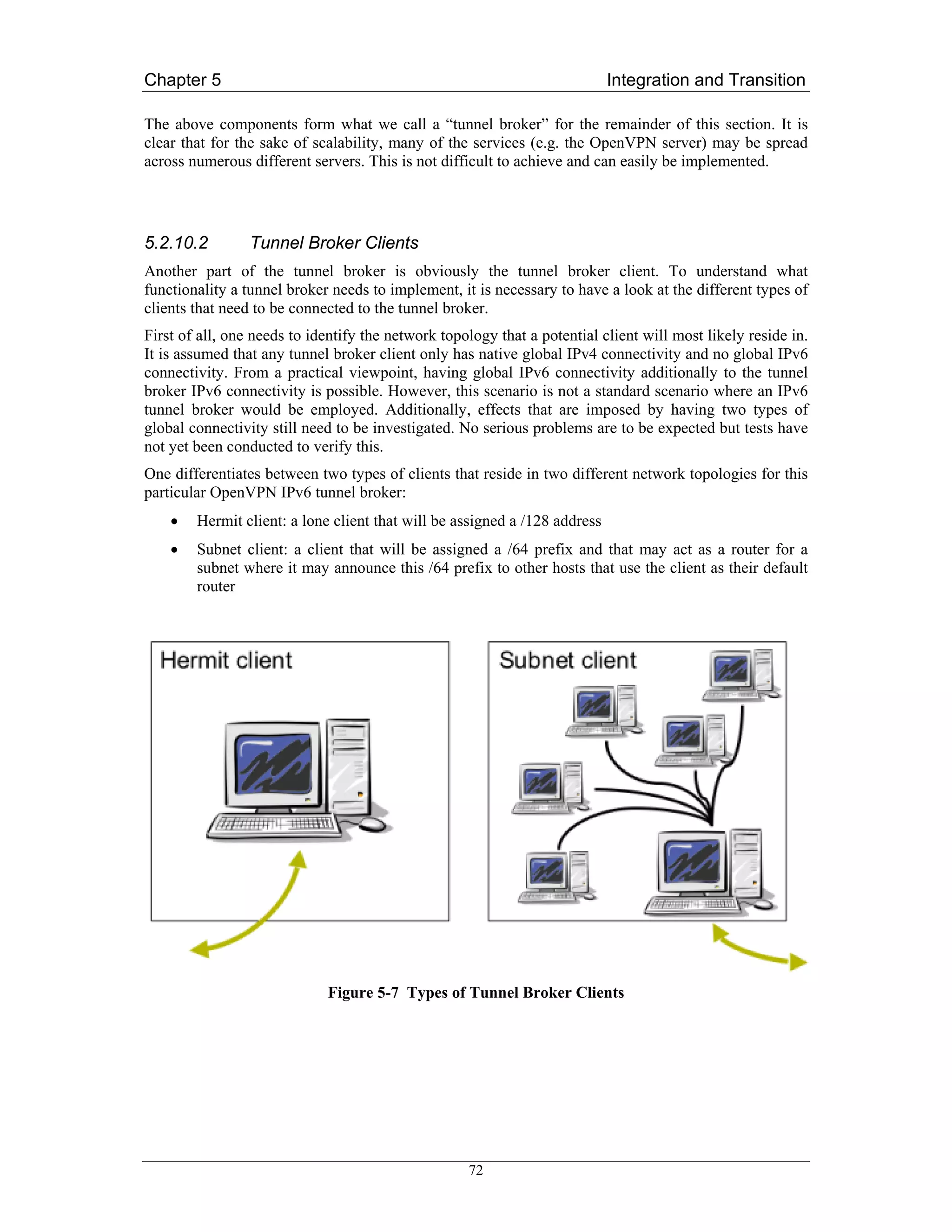
![Chapter 5 Integration and Transition
5.3 Translation Methods
Translation methods are deployed where IPv6-only devices wish to communicate with IPv4-only
devices, or vice-versa and no IPv4-in-IPv6 is used.
5.3.1 SIIT, NAT-PT and NAPT-PT
A translator located in the network layer in the protocol stack is called a “header translator”. Such
mechanisms translate IPv4 datagram headers into IPv6 datagram headers or vice versa. A model that
can be used when implementing this mechanism is presented in RFC 2765 [RFC2765]: “SIIT –
Stateless IP/ICMP Translation Algorithm”.
Network Address Translation with Protocol Translation (NAT-PT), defined in RFC 2766 [RFC2766],
is a service that can be used to translate data sent between IP-heterogeneous nodes. NAT-PT translates
an IPv4 datagram into, as far as possible, a semantically equivalent IPv6 datagram or vice versa. For
this service to work it has to be at the interconnection point between the IPv4 network and the IPv6
network.
Just like existing NATs in the IPv4 world translate between (usually) private IPv4 addresses and
globally routable IPv4 addresses, the NAT part of NAT-PT translates between a globally routable
IPv4 address to an IPv6 address or vice versa as well as from a private IPv4 address to a global IPv6
address. The PT part of the NAT-PT handles the interpretation and translation of the semantically
equivalent IP headers, either from IPv4 to IPv6 or from IPv6 to IPv4. Like NAT, NAT-PT also uses a
pool of addresses, which it dynamically assigns to the translated datagrams.
Dual-stack and tunnel-based mechanisms do not alter any of the data contained in the IP datagram.
This is true both for IPv4 and IPv6 since the communication is end-to-end using only one protocol.
NAT-PT (and NAPT-PT as described below) on the other hand translates the header of the datagram
from IPv6 to IPv4 or vice versa. The result is a new header which is semantically equivalent to the
original header but not equal. It is therefore likely that some of the information is lost during
translation. For example it may happen that a service, which is only available for one protocol, is lost
when converted to another protocol.
RFC2766 also specifies a service called Network Address Port Translation + Packet Translation
(NAPT-PT). This service enables IPv6 nodes to communicate transparently using only one IPv4
address. NAPT-PT maintains a set of port numbers, which it dynamically assigns to sockets located on
the recipient side of the NAPT-PT node.
NAT-PT shares many of the problems normal NAT or the TRT mechanism have, e.g. handling or
rather failing to handle IP addresses embedded in application protocol payloads.
The IETF is currently deprecating NAT-PT (see [AD05] for the rationale), but may rework it to a
more acceptable format. It should be seen as a transition method of last resort. It is highly preferable
that at least one ‘side’ of the networking scenario is dual-stack so that a common, non-translated,
network protocol can be used (IPv4 or IPv6). If this is not possible, and performance permits, an ALG
should be preferred (see below).
5.3.2 Bump in the Stack
The Bump in the Stack (BIS) [RFC2767] (see Figure 5-8) translation mechanism is similar to taking
the NAT-PT approach with SIIT and moving it to the OS protocol stack within each host. Unlike SIIT
however, it assumes an underlying IPv6 infrastructure. Whereas SIIT is a translation interface between
74](https://image.slidesharecdn.com/ipv6deployment-guide-110112200202-phpapp01/75/IPv6-Deployment-Guide-88-2048.jpg)
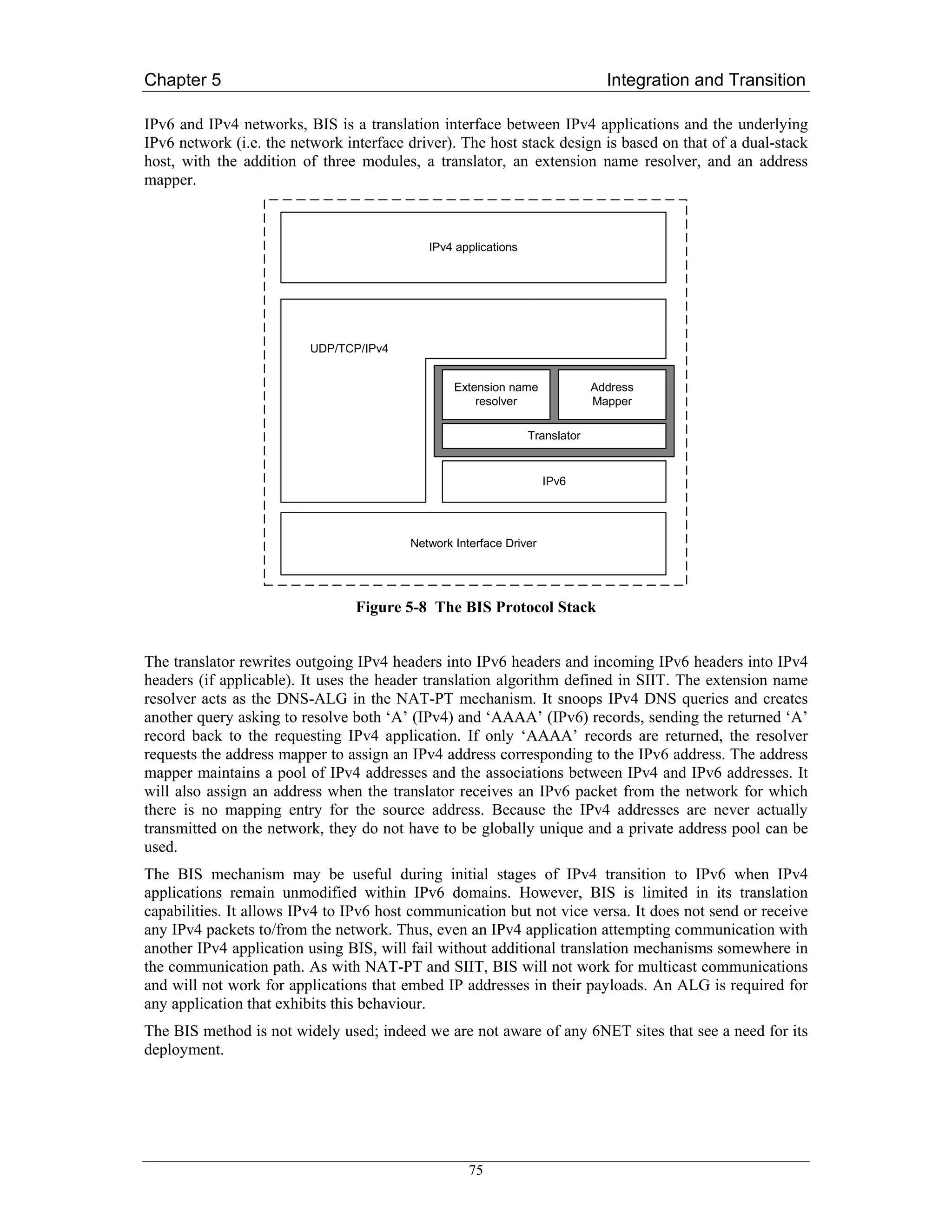
![Chapter 5 Integration and Transition
5.3.3 Bump in the API
The Bump in the API (BIA) [RFC3338] translation mechanism is very similar to that of BIS.
However, instead of translating between IPv4 and IPv6 headers, BIA inserts an API translator between
the socket API and the TCP/IP modules of the host stack (see Figure 5-9).
IPv4 applications
Socket API (IPv4, IPv6)
Extension name Address
Function Mapper
resolver Mapper
TCP/UDP/IPv4 TCP/UDP/IPv6
Network Interface Driver
Figure 5-9 The BIA Protocol Stack
Thus, IPv4 socket API functions are translated into IPv6 socket API functions and vice versa. In this
way, IPv4/IPv6 translation can be achieved without the overhead of translating every packet header.
Like BIS, BIA is based on the addition of three modules: the extension name resolver, the function
mapper and the address mapper. Both the extension name resolver and the address mapper modules
operate in exactly the same way as the corresponding modules in BIS. The function mapper is the
entity that maps IPv4 socket calls to IPv6 socket calls and vice versa. The function mapper does this
by intercepting IPv4 socket API function calls and invoking corresponding IPv6 socket API function
calls in their place. These IPv6 socket function calls are used to communicate with the peer IPv6 host
and are transparent to the IPv4 application that invoked the original IPv4 socket function calls.
The BIA mechanism is intended for systems that have an IPv6 stack but contain applications that have
not been upgraded to IPv6. Thus, BIA may be useful in early stages of transition when there are many
unmodified IPv4 applications within IPv6 domains. BIA allows IPv4 to IPv6 host communication, but
does not specify the reverse case. However, it could be easily extended to cater to IPv6 to IPv4 host
communication (this is also applicable to BIS). The advantage BIA has over BIS is that it is
independent of the network interface driver and does not introduce the overhead of per-packet header
translation. However, BIA exhibits similar limitations to BIS. It will not support multicast
communication without some additional functionality in the function mapper module, and it will not
work for applications that embed IP addresses in their payloads.
The BIA method is, like the BIS method, not widely used. No 6NET sites see a deployment
requirement for it.
76](https://image.slidesharecdn.com/ipv6deployment-guide-110112200202-phpapp01/75/IPv6-Deployment-Guide-90-2048.jpg)
![Chapter 5 Integration and Transition
5.3.4 Transport Relay
A translator located in the transport layer is called a transport relay. The relay is located somewhere
between the communicating nodes and enables IPv6-only hosts to exchange traffic (UDP or TCP) with
IPv4-only hosts. If two nodes, for example a client and an application server, use different protocol
stacks, they couldn’t communicate directly with each other, and traffic has to be passed over a relay.
In case of TCP the relay terminates the IPv6 transport protocol session from the client, and thus acts as
a transport destination endpoint to the client. At the same time it initializes a second IPv4 transport
session with the server, and copies received data from each session to the other. In the case of UDP the
datagram is just translated and forwarded to the target node.
5.3.4.1 Transport Relay Translator
The Transport Relay Translator (TRT) [RFC3142] enables IPv6-only hosts to exchange traffic (TCP
or UDP) with IPv4-only hosts. No modification on hosts is required, the TRT system can be very
easily installed in existing IPv6 capable networks.
A transport relay translator which runs on a dual-stack node can use one protocol when
communicating with the client and one protocol when communicating with the application server. In
such a setting the relay is able to translate in the transport layer all data sent between the client and
application server. For TCP such a translation includes recalculating the checksum, keeping the
necessary state information about which client socket is connected to which server socket and
removing this state when the client ends its communication. With UDP the checksum is mandatory
when using IPv6 but not when using IPv4. UDP is a connectionless protocol and in theory it is
impossible for a relay to know which UDP datagrams belong to the same session. A UDP relay
implementation will typically assume that a UDP datagram that follows another with the same source
and destination within a certain time interval, belong to the same session.
The TRT system can work with most of the common Internet applications: HTTP, SMTP, SSH, etc.
The transition mechanism operation is relatively simple:
The IPv6 host uses a DNS-ALG as its nameserver to resolve its DNS queries. The IPv6 host, when
asking its nameserver for the IPv6 address (AAAA record) of an IPv4-only host, will receive an IPv6
address (AAAA record) from the DNS-ALG which was specially constructed from the IPv4 address
(A record), instead of an error message with the answer that no IPv6 address could be found
corresponding to the query. The constructed addresses consist of a special network prefix associated
with the transport relay and a host ID (the lower 64 bits) that embeds the IPv4 address of the remote
host. Such a DNS-ALG has been developed as part of the 6NET project and has been tested
extensively with very good results.
The network is set up such that packets destined for addresses with the special network prefix are
routed to the TRT relay node. The TRT then intercepts transport sessions and acts towards the client
node as the destination endpoint of an IPv6 session and acts towards the server node as the source for
an IPv4 session, copying all data it receives from each session to the other.
77](https://image.slidesharecdn.com/ipv6deployment-guide-110112200202-phpapp01/75/IPv6-Deployment-Guide-91-2048.jpg)
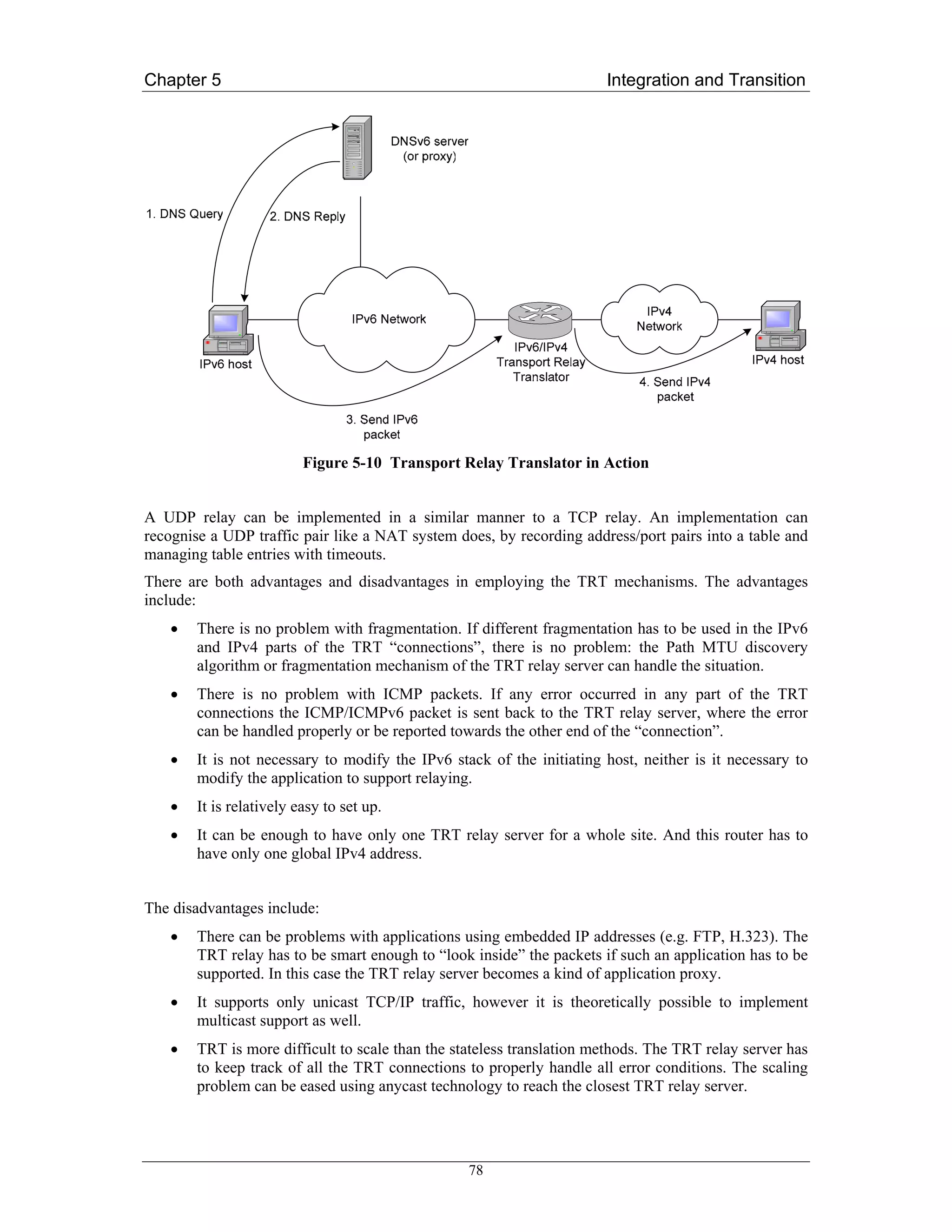
![Chapter 5 Integration and Transition
• The TRT relay server can generate a major security problem, since it can be used as an
intermediate hop to reach IPv4 servers. The served community of a TRT relay server has to be
carefully controlled by packet filtering or access control lists. To reduce the problem site local
addresses could be used for accepting incoming IPv6 packets (Note that within the IETF there
are currently plans to deprecate site-local addresses and replace them with a new addressing
scheme for “private” addressing within a site).
• TRT requires a specially configured DNS server to run.
• Due to the nature of the TCP/UDP relaying service, it is not recommended to use TRT for
protocols that use authentication based on source IP address (e.g., rsh/rlogin).
• IPSec cannot be used across a TRT relay.
The TRT relay is used in the Tromso scenario within the 6NET project, as described in Chapter 13.
5.3.5 SOCKS
SOCKS [RFC1928] is another example of a transport relay but it is usually referred to as a “proxy
protocol for client/server environments”.
A SOCKS proxy works in a similar fashion as a traditional transport relay, but there are minor
differences, which we will now describe.
When a client wants to connect to an application server it first sets up a connection to a well known,
preconfigured proxy server using a special proxy protocol. The client informs the proxy about the IP
address and the port number of the application server it wants to communicate with. The proxy server
is now responsible to set up a connection to the application server. As soon as this connection is up
and running the proxy relays packet between the client and application server hiding the actual
connection.
SOCKS includes two primary components: a SOCKS server and a SOCKS client library. The server
component is located in the application layer while the client component is located between the client
application and the transport layer.
Before an application client can use SOCKS it has to be modified (“socksified”). This can be done in
two different ways: If the source code is available it can be compiled together with the SOCKS client
library using a set of pre-processor directives. If one has instead only precompiled binaries for an
application, but the operating system supports dynamic linking of shared libraries one can change
some environment variables in the operating system so that the client uses SOCKS instead of the
default network libraries.
RFC 3089 [RFC3089] presents a SOCKS-based IPv6/IPv4 gateway mechanism that supports both
IPv6 to IPv4 communication and IPv4 to IPv6 communication. This RFC also contains a link to two
different implementations of the mechanism described.
No 6NET partners are currently using SOCKS for IPv6 transition purposes.
5.3.6 Application Layer Gateway
An Application Layer Gateway (ALG) is a common mechanism to allow users behind firewalls or
behind a NAT gateway to use applications that would otherwise not be allowed to traverse the firewall
or NAT gateway. A common example for an ALG is a classical HTTP proxy like “squid” or
“wwwoffle”.
79](https://image.slidesharecdn.com/ipv6deployment-guide-110112200202-phpapp01/75/IPv6-Deployment-Guide-93-2048.jpg)
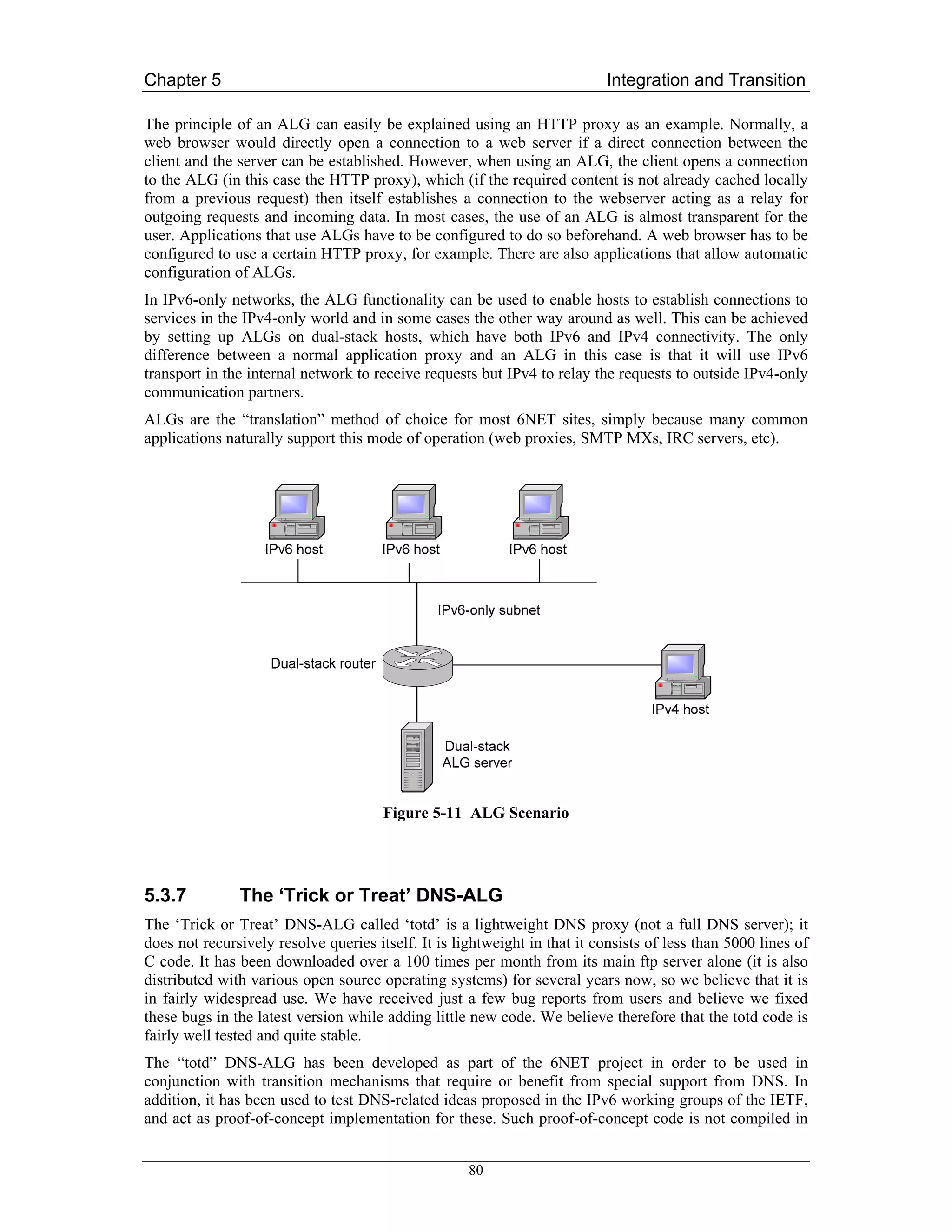
![Chapter 5 Integration and Transition
5.4 Configuration Examples: Dual Stack
This section, as well as the following two, includes installation and configuration examples for most of
the implementations of the tools and mechanisms previously described in this chapter.
Generally, adding IPv6 functionality to existing IPv4 interfaces – if it is supported in the operating
system/on the platform – is often a simple task. Nevertheless, as one basically adds a complete new
IPv6 network living next to the existing IPv4 network, one has to think about internal and maybe
external routing structures. These may differ from those used in IPv4, as not all of the current IGPs
(like OSPFv2) are capable to route IPv6 traffic. Instead it may happen that new protocols (e.g.
OSPFv3) need to be deployed.
Information on how to switch on IPv6 on any platform is included in Appendix B. As IPv6 becomes
more and more common it is likely that this information will become unnecessary. Very soon all
operating systems and router platforms will have IPv6 switched on by default.
Configuration examples for routing protocols are covered in Chapter 6. We would like the reader to
refer to that chapter to learn how to set up inter or intra-domain routing with either iBGP, OSPFv3, IS-
IS or RIPng for most platforms.
5.4.1 Dual-stack VLANs
Using VLANs for IPv6 site deployment is not really a transition tool but it is a method that is
becoming more commonly used for dual stack IPv6 deployment in site networks because it is so easy
if the network already makes use of the VLAN technique. One just injects (new) IPv6 subnets/links
into the existing IPv4 VLANs. In a smaller size network, there may be 10-15 VLANs, each just
carrying traffic for one IPv4 subnet. In such situations, one can take advantage of the VLAN
segregation of traffic to connect IPv6 routers such that a single IPv6 prefix (a /64 prefix) is injected
into each IPv4 VLAN that requires dual-stack networking. Hosts in such subnets can then
autoconfigure IPv6 addresses in addition to their IPv4 addresses or make use of DHCPv6 if the service
is implemented. In this case, the IPv6 routing hierarchy may be IPv6-only, and exist in parallel to the
IPv4 network infrastructure. The IPv6 link offsite may also be separate.
It is important in such an instance that IPv6 filters and access control lists are deployed to prevent IPv6
being a back door for hackers to enter the (IPv4) network.
See [Cho04b], an IETF I-D produced within the 6NET project, for more details.
5.4.1.1 Configuring an interface on a Linux host to become part of a VLAN
The following example shows how a physical interface of a Linux host (i.e. eth0) is trunked to become
part of a tagged VLAN. The only prerequisite is that support for VLANs needs to be switched on
before compiling the kernel.
# ip link set <trunked interface> up;
# /usr/sbin/vconfig add <trunked interface> <VLAN-ID>
# ip link set <trunked interface>.<VLAN-ID>
82](https://image.slidesharecdn.com/ipv6deployment-guide-110112200202-phpapp01/75/IPv6-Deployment-Guide-96-2048.jpg)
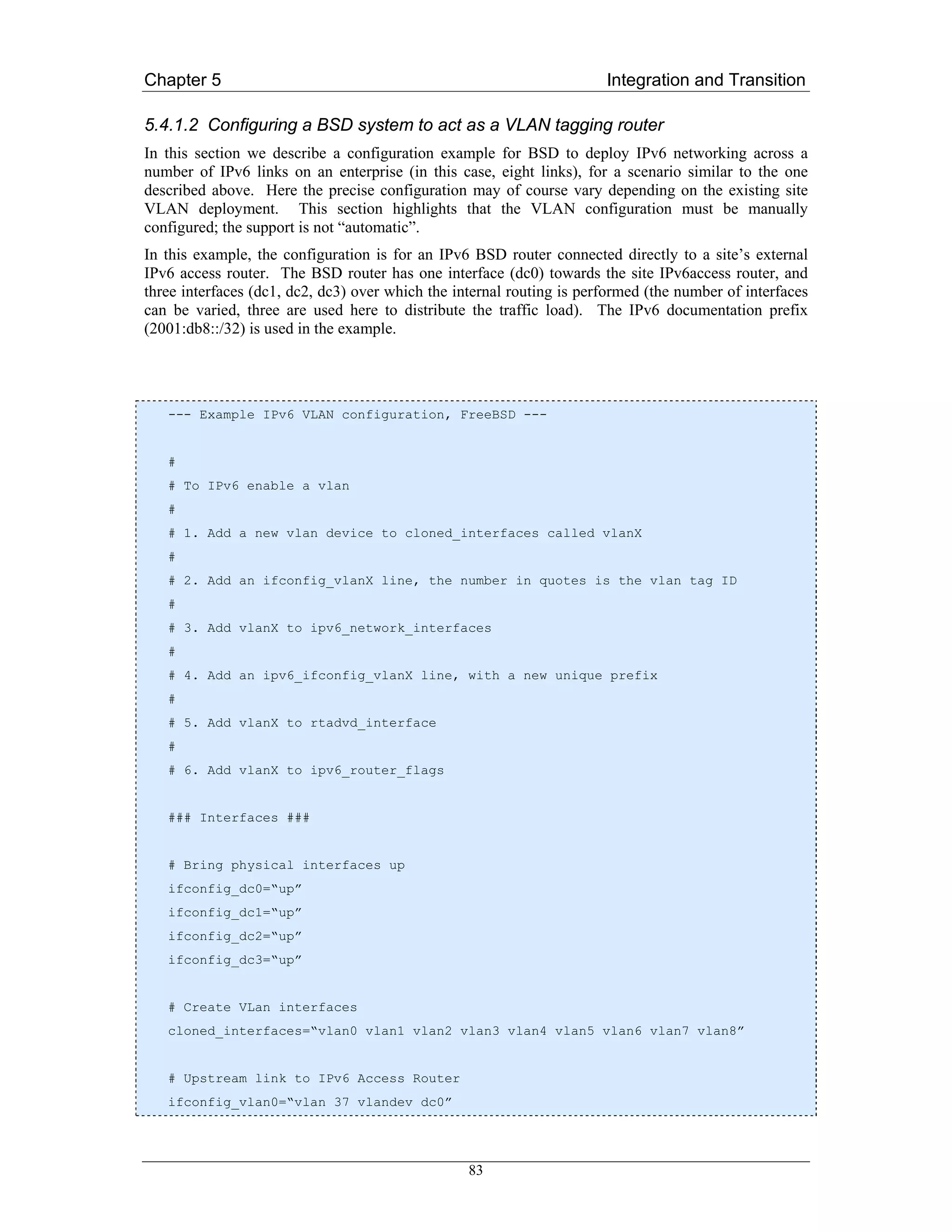
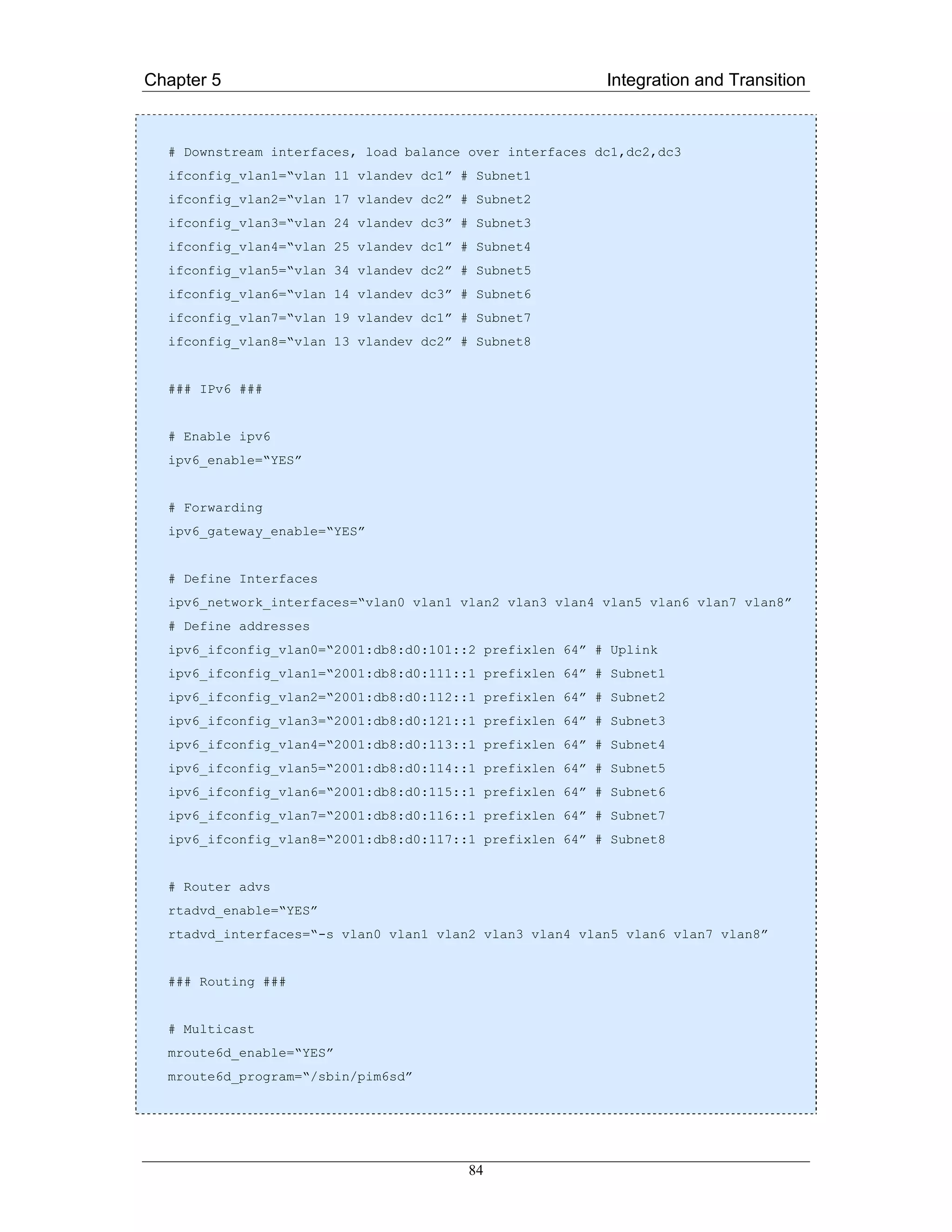

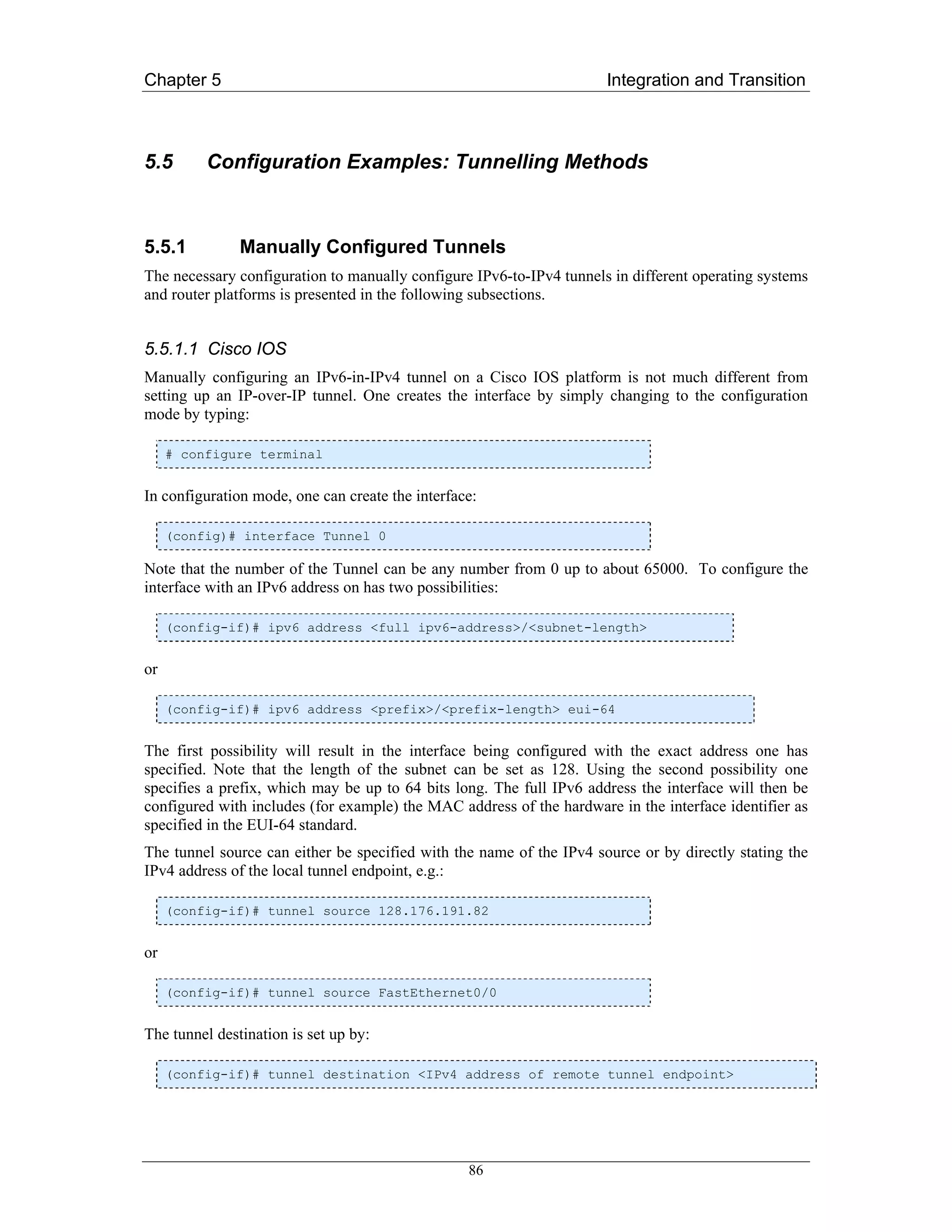
![Chapter 5 Integration and Transition
Finally one has to set the tunnel mode to “ipv6ip” to specify the correct encapsulation and
decapsulation.
(config-if)# tunnel mode ipv6ip
With the “ipv6 route” command one can configure routes for tunnel interfaces just like with any other
interface.
5.5.1.2 Juniper (JunOS)
If you have Tunnel PIC installed in your Juniper router, you can configure IPv6 over IPv4 tunnels. To
do this, you configure a unicast tunnel across an existing IPv4 network infrastructure.
Configuration example:
Router #1:
[edit]
interfaces{
gr-1/0/0{
unit0{
tunnel{
source 128.176.191.82;
destination 128.176.184.7;
}
family inet6{
address 2001:db8:ffff::ffff:1/112
}
}
}
}
Router #2:
[edit]
interfaces{
gr-1/0/0{
unit0{
tunnel{
source 128.176.184.7;
destination 128.176.191.82;
}
family inet6{
address 2001:db8:ffff::ffff:2/112
}
}
}
}
87](https://image.slidesharecdn.com/ipv6deployment-guide-110112200202-phpapp01/75/IPv6-Deployment-Guide-101-2048.jpg)
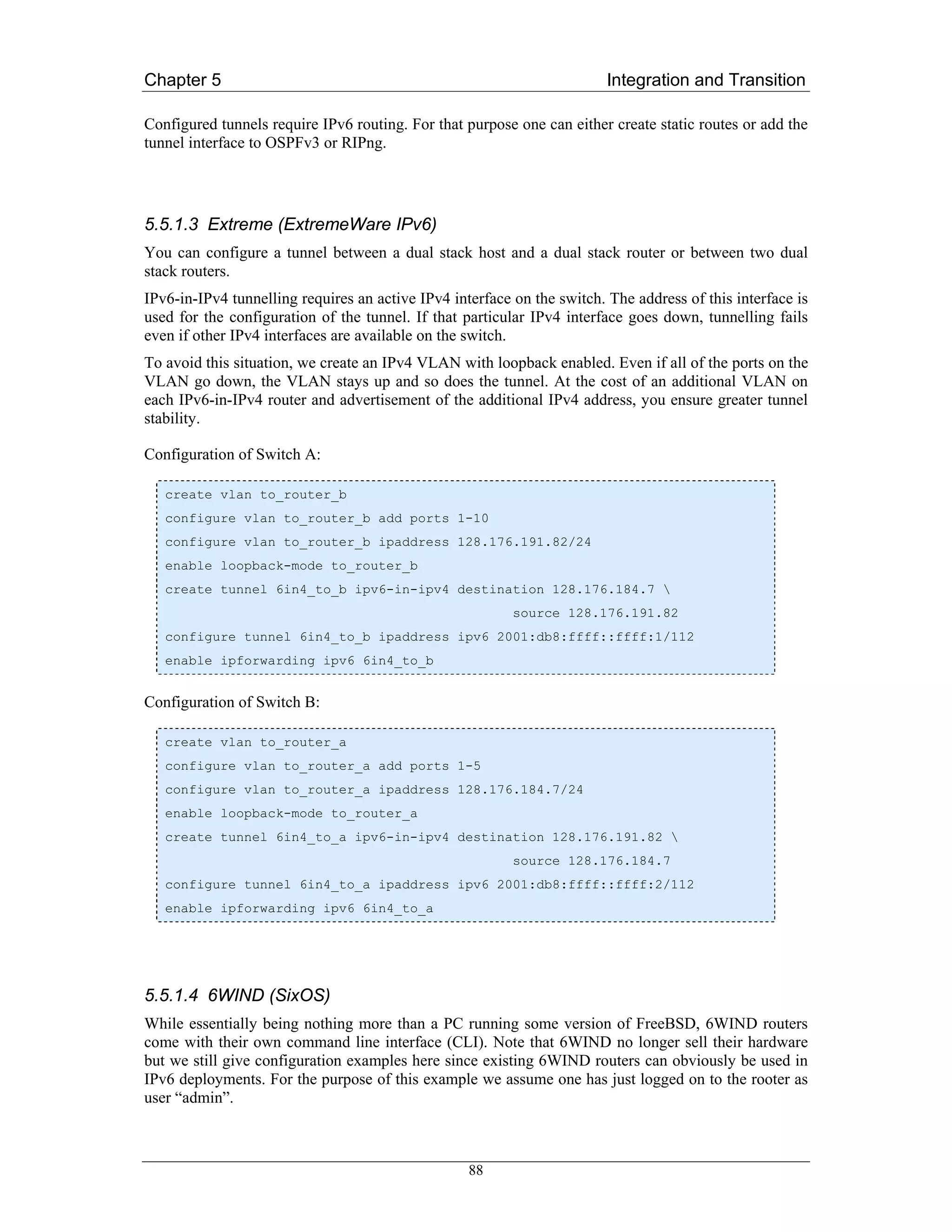
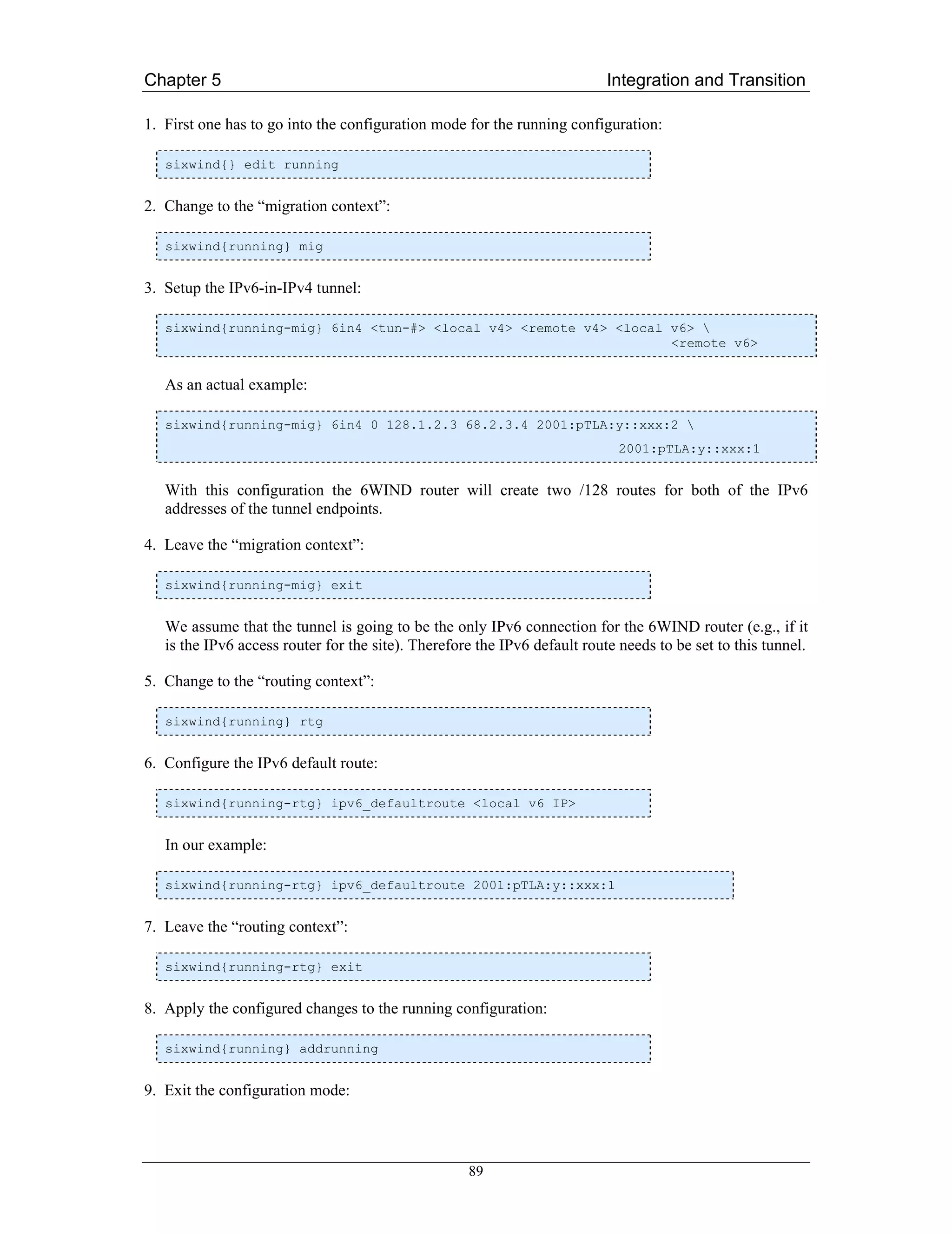
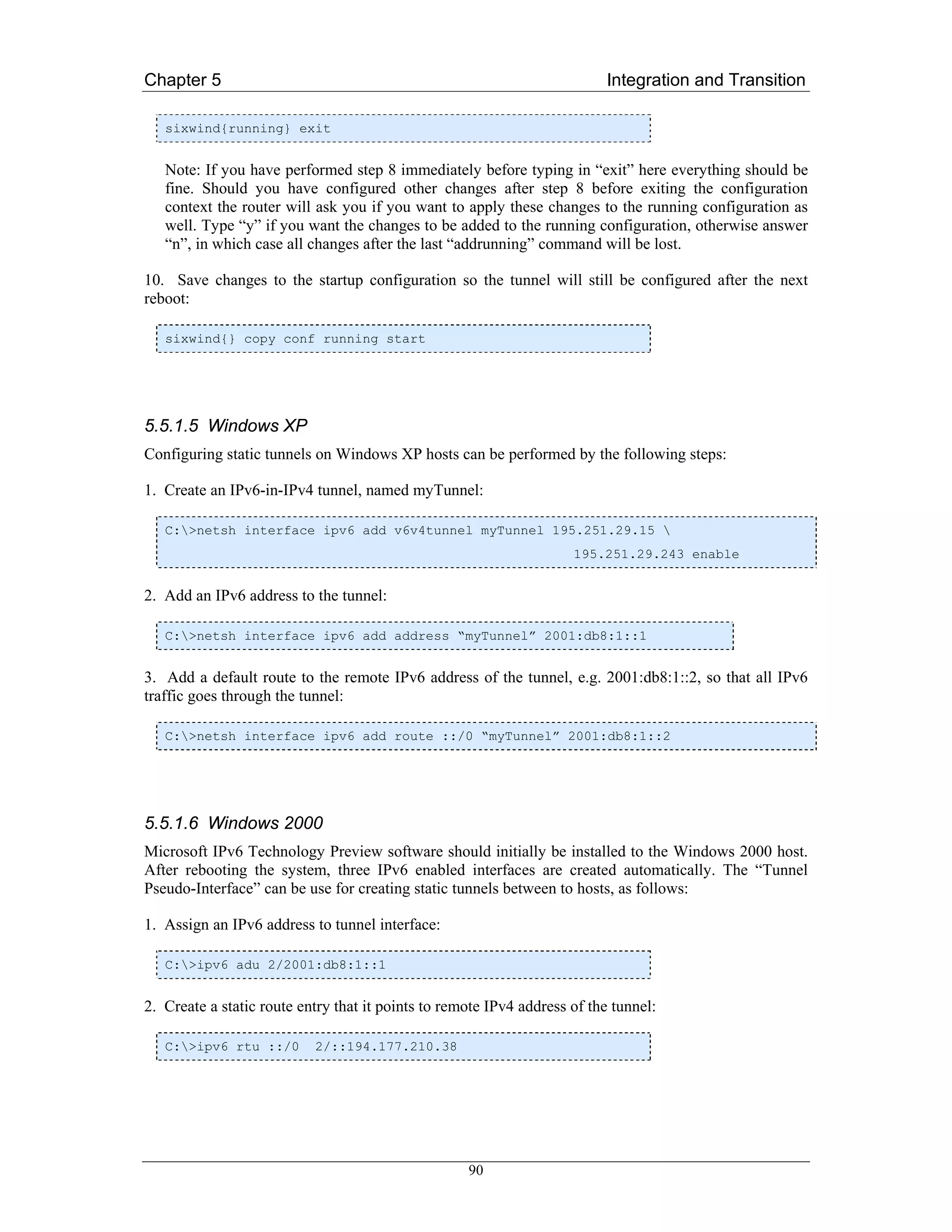
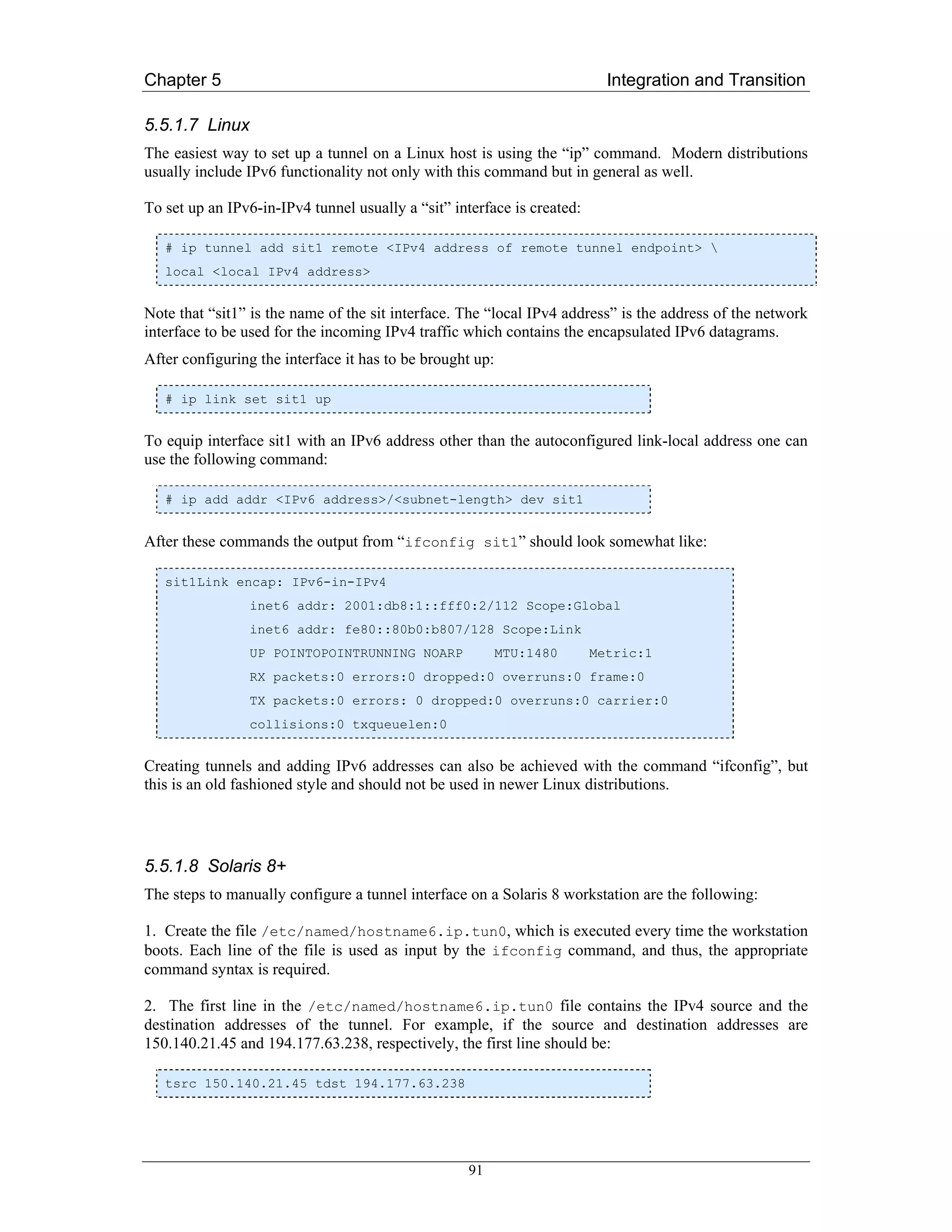
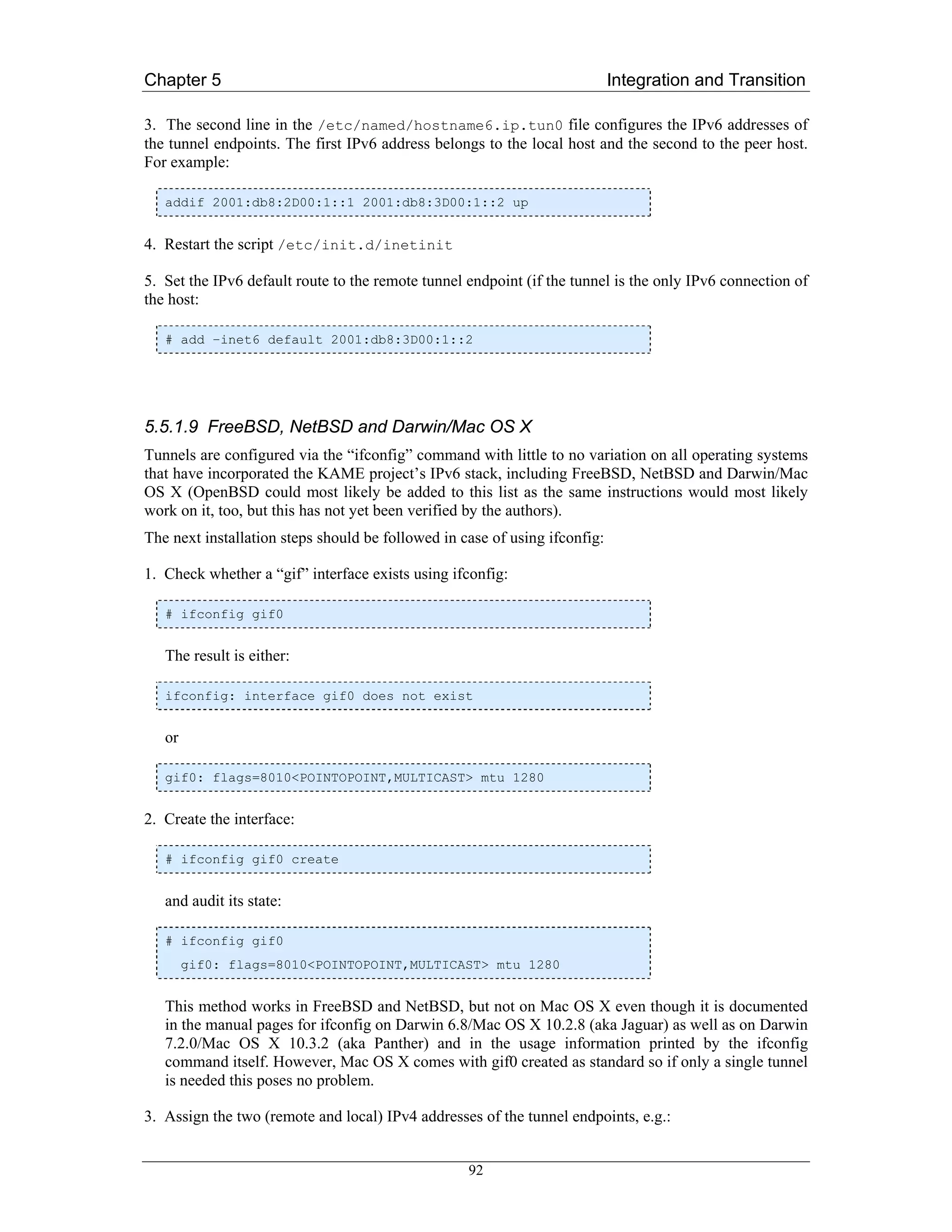
![Chapter 5 Integration and Transition
# ifconfig gif0 tunnel 130.1.2.3 134.5.6.7
4. Assign the local IPv6 addresses of the tunnel:
# ifconfig gif0 inet6 alias <Local_IPv6_TUNNEL_ ADDR>
prefixlen <Length of prefix for tunnel address>
For example:
# ifconfig gif0 inet6 alias 2001:DEAD:BEAF:ABBA::1 prefixlen 64
Note that the “alias” keyword is not necessary on all BSD OSes, but it never hurts to include it. The
prefix length may be omitted when it its equal to 64 since 64 is the default. When the user has only
one or a few tunnels, it is recommended to use a 64 bit prefix length as that will typically also be
used for other (less virtual) interfaces. However, longer (more specific) prefix lengths are not a
problem and may be an attractive choice for tunnel brokers hosting many tunnels from a limited
address space. It is wise to avoid prefixes longer than 126 bits as some implementations have
reportedly had problems with 127 and 128 bit long prefixes, even though the authors are not
currently aware of any such problems in recent releases of any operating system. Still, taking a
prefix of 120, 126 or even 112 bits in length barely wastes address space and may be worthwhile to
avoid any potential problems. For more details on this please refer to RFC 3627 [RFC3627].
In the above commands it is also possible to specify both the source and destination IPv6 addresses
of the tunnel but it is not necessary as the routing subsystem does not need to know the remote
end’s global address (it is enough to be able to talk to the next hop using link-local addressing).
Though for administrative reasons it may be attractive to assign the destination address too. Some
non KAME derived implementations even require the global IPv6 addresses of both tunnel
endpoints to be set. This is accomplished by substituting the above command with, for example:
# ifconfig gif0 inet6 alias 2001:DEAD:BEAF:ABBA::1
2001:DEAD:BEAF:ABBA::2 prefixlen 128
Actually, as routing over an interface can work without assigning global addresses at all, it should
not be necessary to assign any of them. Indeed, KAME derived IPv6 stacks do not require global
IPv6 addresses to be assigned to a tunnel interface (as tested by the author with NetBSD and
FreeBSD 3.x). In that case, one needs to explicitly add a route over the tunnel interface to the link-
local address of the remote tunnel end (or run a routing protocol that will figure it out for itself
using the well-known multicast address). For example, to add a default route over a tunnel interface
to a remote end with link-local address fe80::2, one would add a route like this:
# route add –inet6 default fe80::2%gif0
or
# route add –inet6 default –ifp gif0
Such unnumbered tunnels will typically only make sense when both tunnel endpoint use a KAME
derived IPv6 stack as other implementations usually don’t support unnumbered tunnels.
93](https://image.slidesharecdn.com/ipv6deployment-guide-110112200202-phpapp01/75/IPv6-Deployment-Guide-107-2048.jpg)
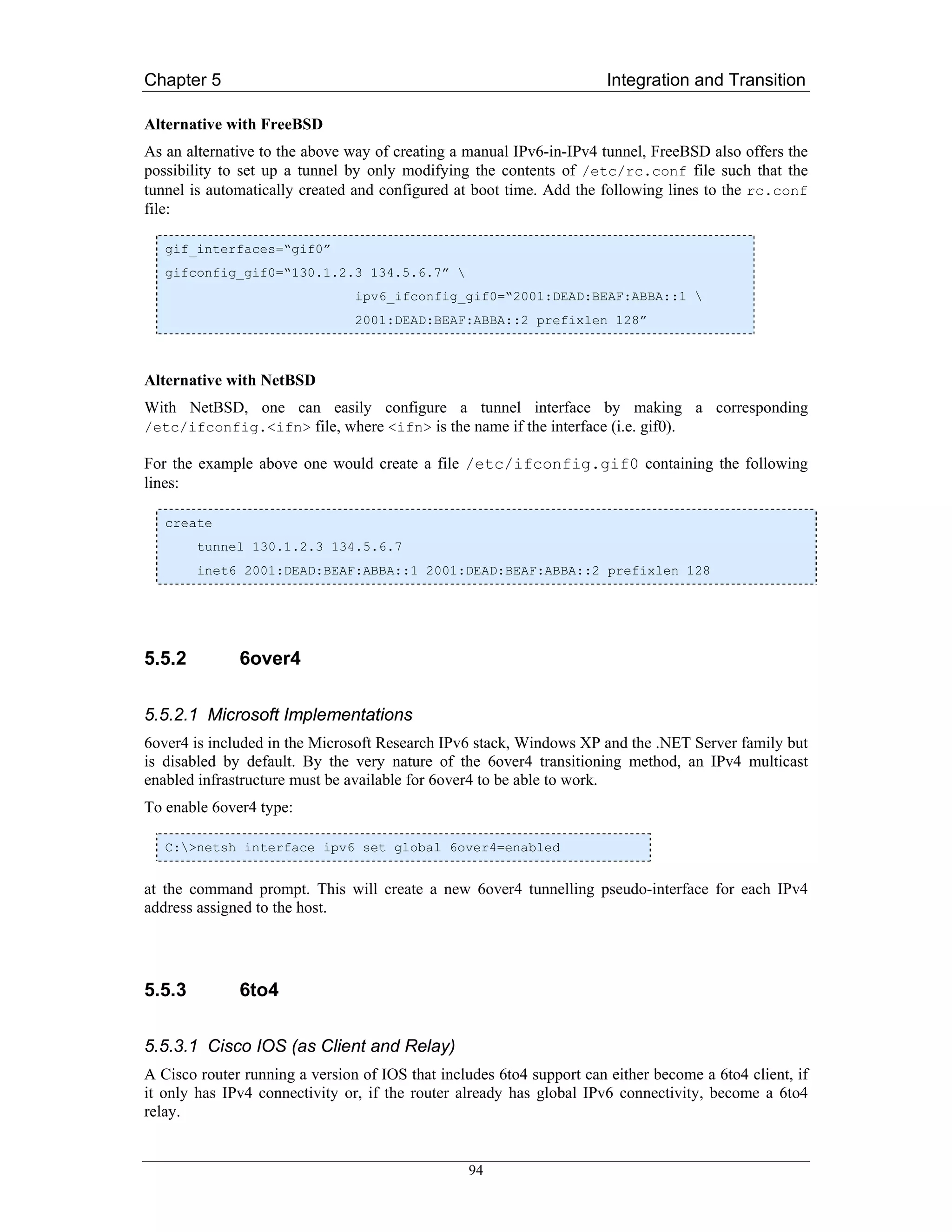
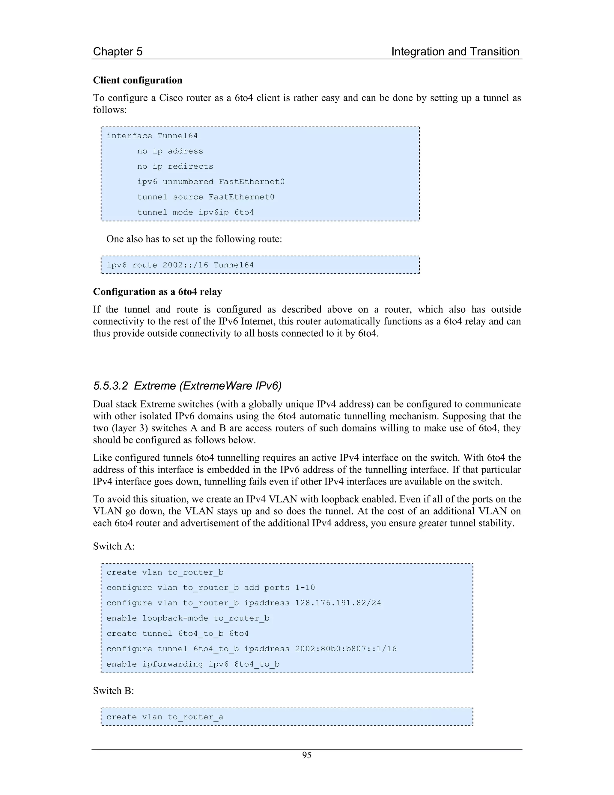
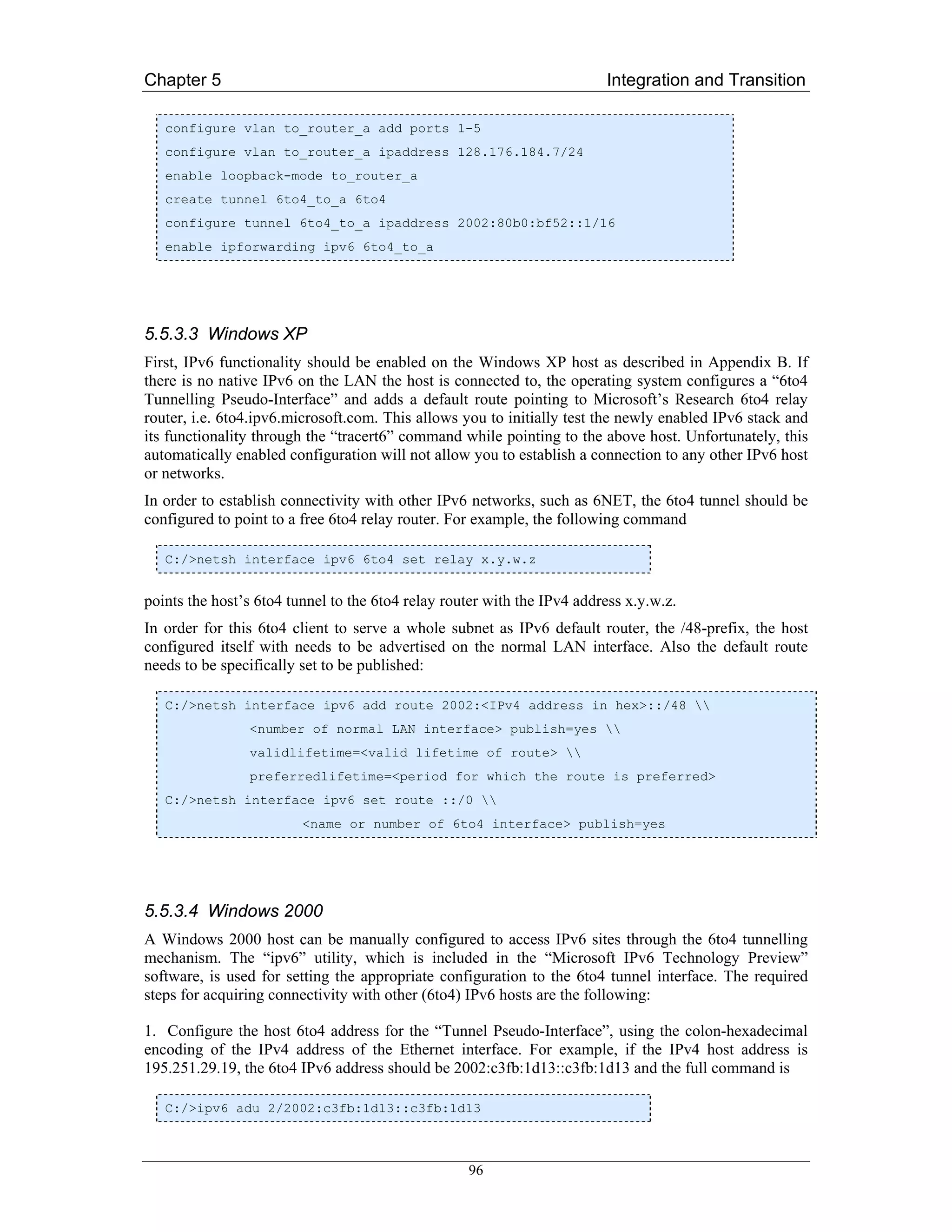
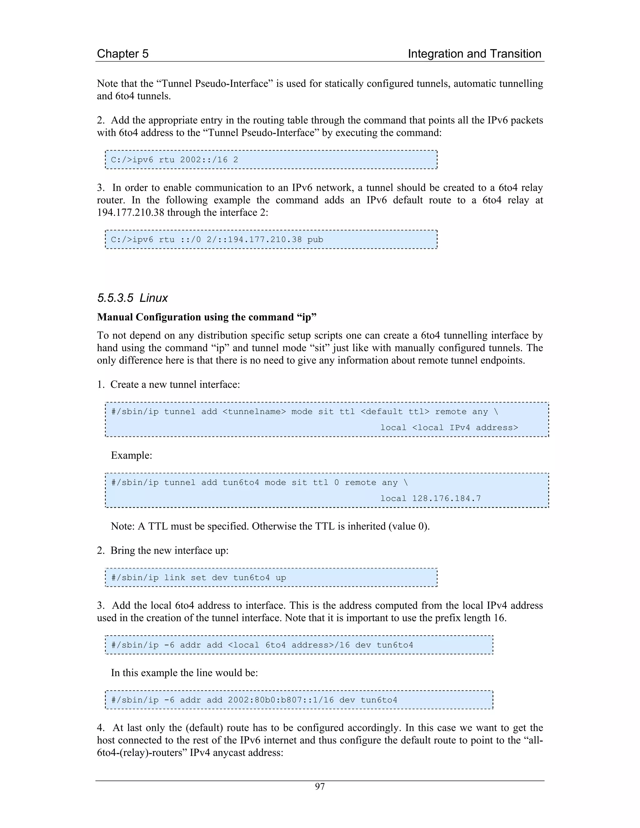
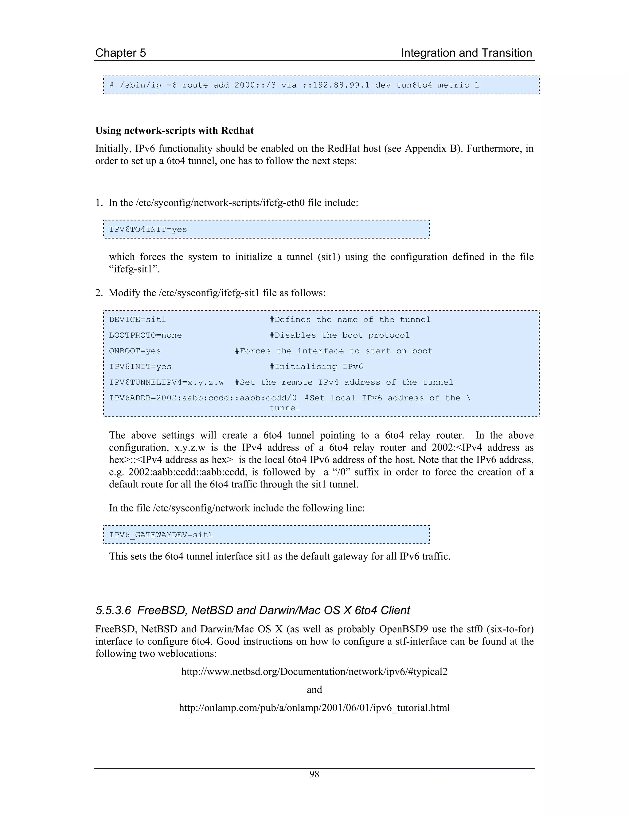
![Chapter 5 Integration and Transition
6to4 with NetBSD’s 6to4-script (Perl)
The easiest way to configure 6to4 on NetBSD (may also work on the other OSes) is to install the Perl
script called “6to4”, that comes with NetBSD itself. The script uses a configuration file called
6to4.conf in which all the needed configuration information is collected and properly commented. On
can install the 6to4 script either manually or from NetBSD’s pkgsrc system where it is found in
/usr/pkgsrc/net/6to4.
5.5.3.7 BSD with Zebra
In this example the router is configured to advertise the 6to4 anycast prefix 192.88.99.0/24 using
OSPFv2 [RFC3068], and to advertise the 6to4 prefix 2002::/16 [RFC3056] via BGP.
With FreeBSD, the file “/etc/rc.conf” is use for system-level configuration. Here one should add:
ifconfig_xl0_alias0=“inet 192.88.99.1 netmask 0xffffff00”
stf_interface_ipv4addr=“192.88.99.1”
stf_interface_ipv6_ifid=“::”
ipv6_gateway_enable=“YES”
The first listed command configures the IPv4 anycast prefix as an alias for the x10 interface. Note that
in real deployments, x10 will have to be replaced by an address corresponding to the used physical
interface with IPv4 connectivity. The second command specifies the address with which the IPv6 6to4
address for the relay router is created (the bits 16-47 of the IPv6 address). The third command sets all
the site and interface-id bits to zero. The last command finally enables IPv6 forwarding on the router.
However, the file “rc.conf” can’t be used to configure everything. For that reason some manual tuning
of the file “rc.local” is also needed; the script is run after the processing of rc.conf has finished.
ifconfig stf0 inet6 2002:c058:6301:: prefixlen 16 anycast
/usr/local/sbin/zebra -d
/usr/local/sbin/bgpd -d
/usr/local/sbin/ospfd -d
/usr/local/bin/vtysh -b
The first command adds an “anycast” flag to the IPv6 6to4 address, so that it is not used as a source
address in outgoing packets. The next three commands start zebra routing processes in the
background. Finally the last command leads to “/usr/local/etc/Zebra.conf” being read and fed to the
respective routing process as a configuration file.
The relevant parts of the Zebra configuration file /usr/local/etc/Zebra.conf” are:
router bgp 1741
no bgp default ipv4-unicast
neighbor 2001:708::2 remote-as 1741
neighbor 2001:708::2 description 6net-rtr
neighbor 2001:708:0:1::625 remote-as 1741
99](https://image.slidesharecdn.com/ipv6deployment-guide-110112200202-phpapp01/75/IPv6-Deployment-Guide-113-2048.jpg)
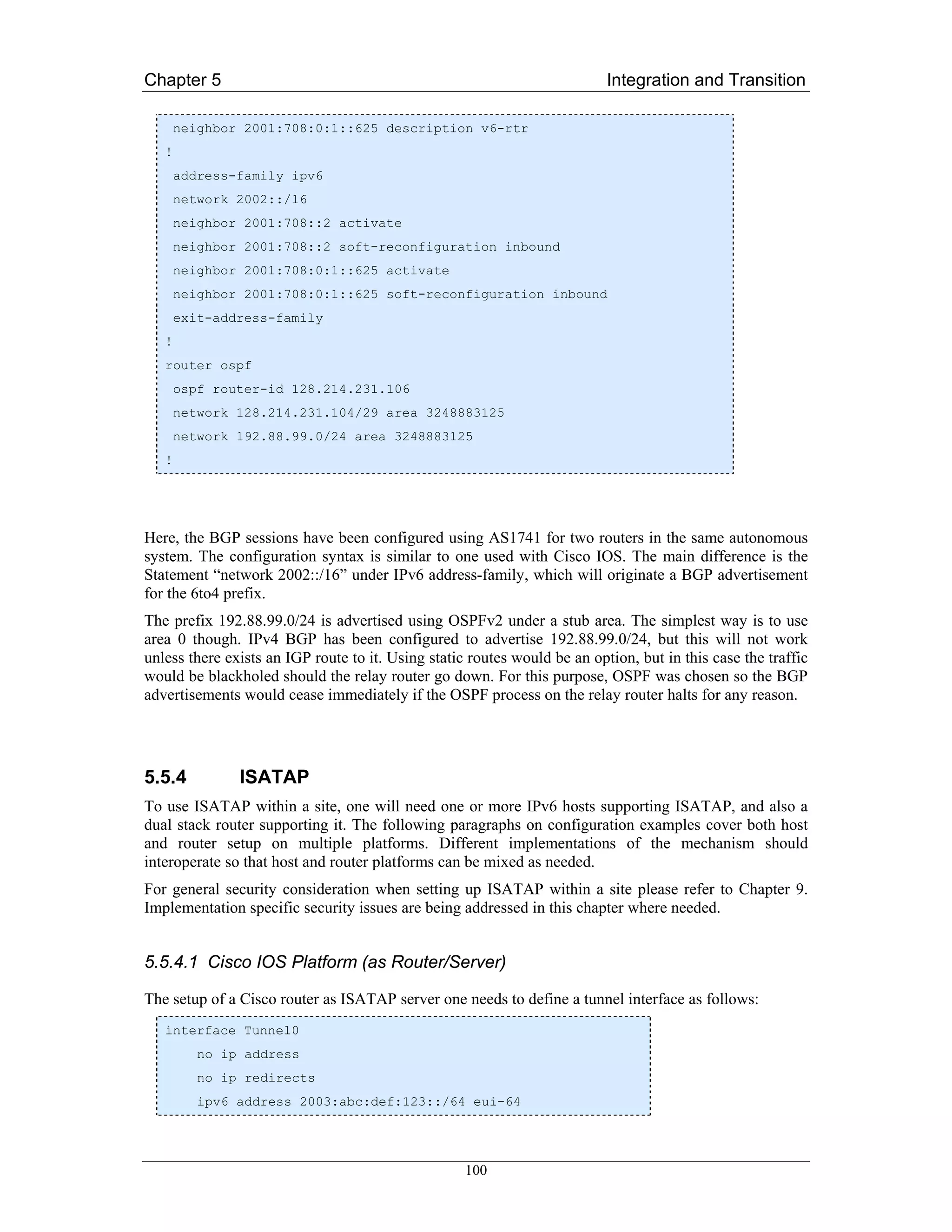
![Chapter 5 Integration and Transition
no ipv6 nd suppress-ra
tunnel source FastEthernet0
tunnel mode ipv6ip isatap
If an ISATAP supporting client is set up to know about this Cisco router it will be able to
automatically configure its interface with the prefix above. The last 64 bits will be based on the EUI-
64 address and include the IPv4 address of the client as specified in the ISATAP draft [TGTT05].
According to present experience with ISATAP it does not matter which interface is specified as the
tunnel source as long as it has an IPv4 address reachable by the clients. One can also specify an
address directly.
5.5.4.2 6WIND (as router/server)
The following configuration example was tested on a 6WINDgate 6231 running version 6.3.0b12 of
SixOS.
Configuring a 6WIND router to become an ISATAP router is really rather easy and consists mainly of
only two commands, one specifying the IPv4 address of the tunnelling interface the other defining the
prefix to use for the global IPv6 addresses in the ISATAP subnet. This configuration enables the
router to give itself a valid global (ISATAP style) IPv6 address as well as to send out router
advertisements to possible clients.
For the following example we assume that one has logged on to the router as user “admin” or as a user
with similar permissions.
1. The first step in the configuration is of course to switch to the configuration context for the
configuration file one wants to edit which in the case of this example is the running configuration.
Within the configuration context one has to enter the migration context:
sixwind{} edit running
sixwind{running} mig
2. Now follows the actual ISATAP configuration. First one has to configure an “ISATAP router”, that
is a separate routing process for the outgoing IPv4 interface one uses for the tunnelling. It is possible
to define several of these processes each with a different number and possibly different IPv4
addresses.
The theoretic command for this configuration is:
sixwind{running-mig} isatap_router 'number' 'address_v4' ['address_v4']
As ‘number’ one specifies the number of the ISATAP process, ‘address_v4’ is the IPv4 address of the
interface the automatic tunnels end on. The optional ‘address_v4’ feature is given as either “up” or
“down” and defines configured process is switched on or off. If no state is given the default is “down”.
Later on the state of an ISATAP routing process can also be changed by the command
sixwind{running-mig} isatap_router 'number' 'state'
In our example however we immediately specified the state as “up”:
sixwind{running-mig} isatap_router 1 128.176.191.74 up
101](https://image.slidesharecdn.com/ipv6deployment-guide-110112200202-phpapp01/75/IPv6-Deployment-Guide-115-2048.jpg)
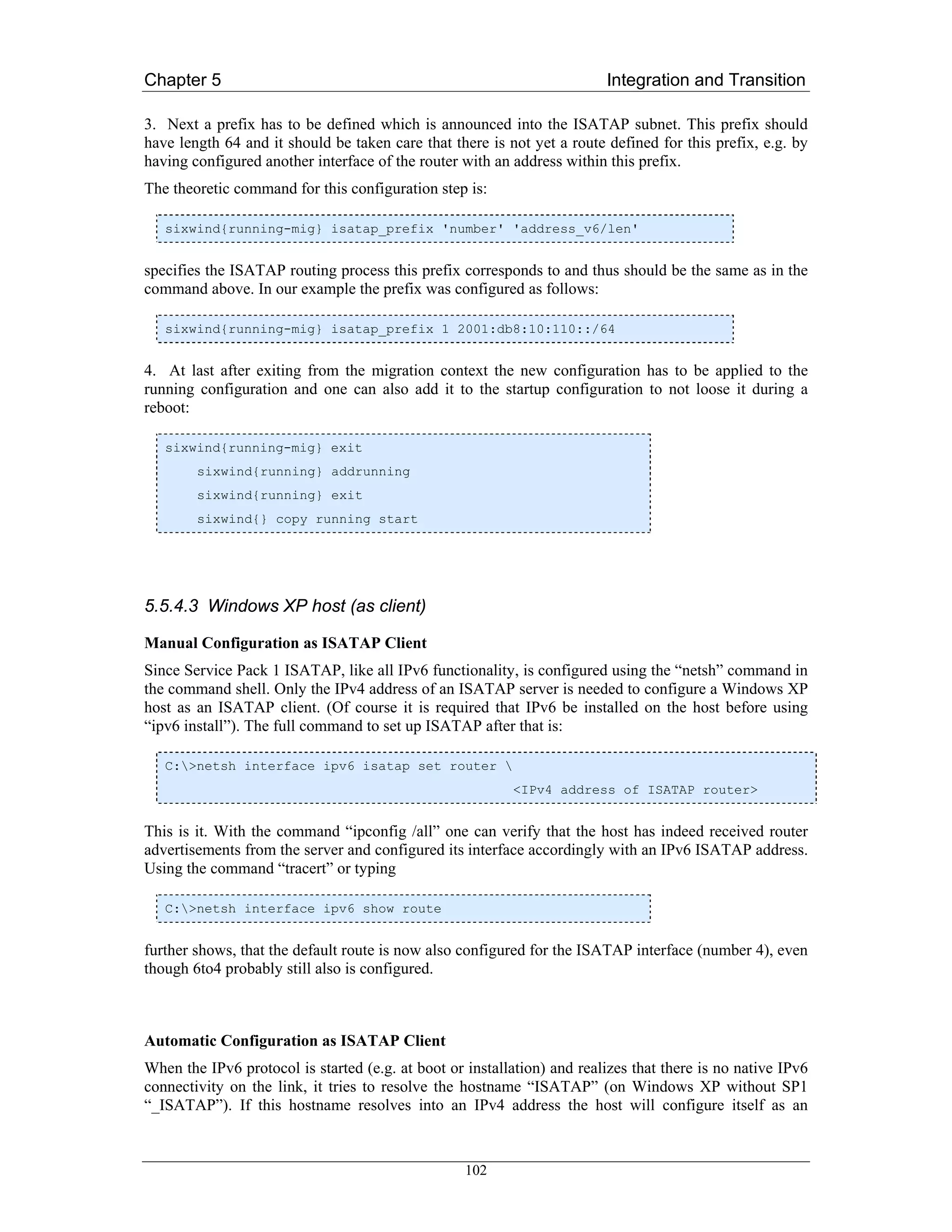
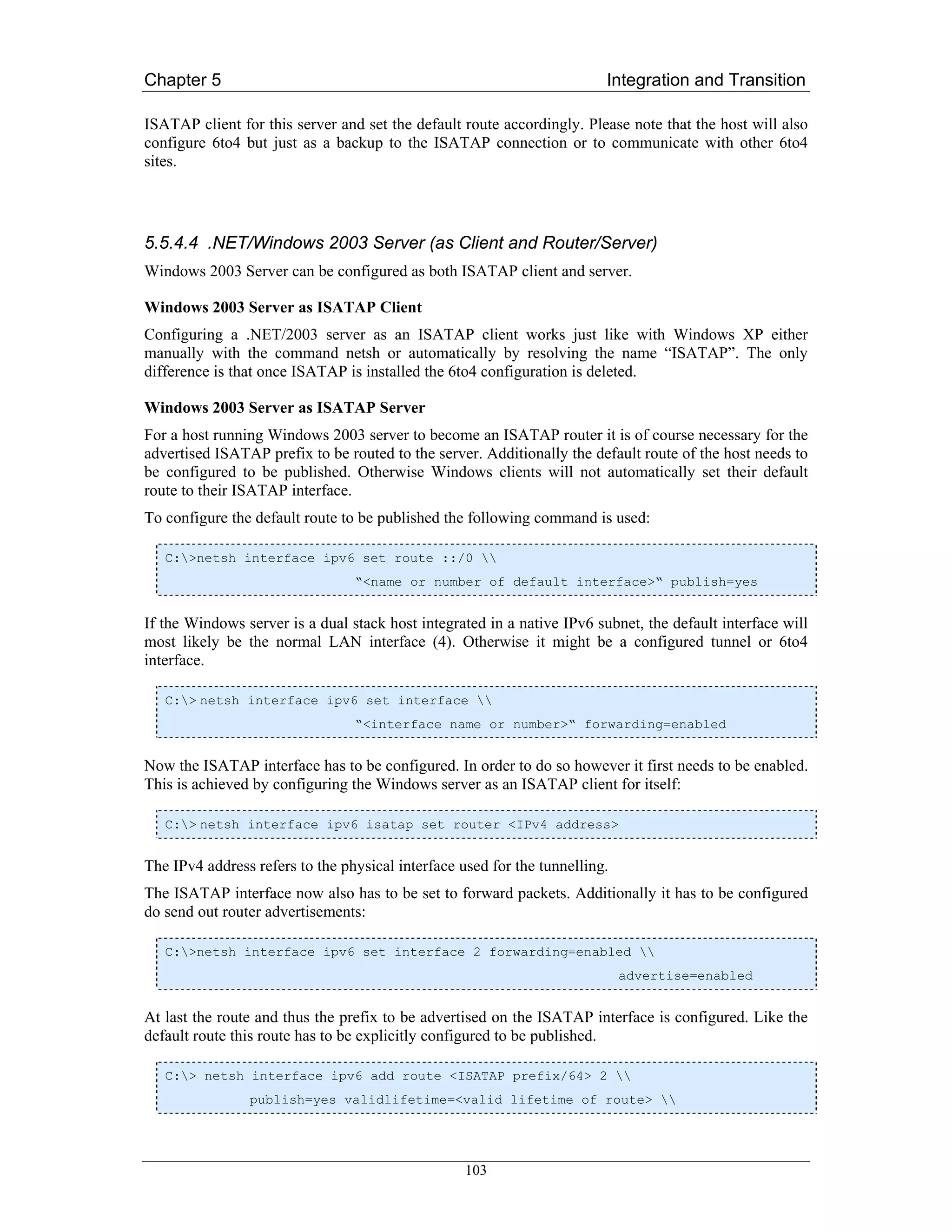
![Chapter 5 Integration and Transition
preferredlifetime=<period for which this route is preferred>
The time periods can be specified in seconds (s), minutes (m), hours (h) or days (d) (e.g. 1d2h3m4s).
The default for validlifetime is eternity. If no preferredlifetime is given, the default is the value for
validlifetime.
5.5.4.5 Linux (as Client and Router/Server)
ISATAP has been included in the Linux kernel by the USAGI project [USAGI]. It can thus be patched
into any present kernel sources and compiled as is described further down. One also needs the iproute
package from USAGI.
Patching the Kernel
First one has to download the newest USAGI patch for the kernel one wants to patch, which are
available on USAGI’s pages at
ftp://ftp.linux-ipv6.org/pub/usagi/
Of course it is best to use stable versions.
Once downloaded and unpacked one can patch the existing kernel sources in /usr/src/linux by typing:
#patch –p1 <usagi-linux2<4,5 or 6>-stable-<snapshot>-<kernel-ver>.diff
After the sources have been patched the kernel needs to be configured by typing
# make xconfig
The section ‘networking options’ contains the new features. Here ‘IPv6: ISATAP interface support
(EXPERIMENTAL)’ needs to be chosen. Please note that there were times when the ISATAP
protocol was not favoured all the time and that ISATAP support is not available in all kernel versions.
Building USAGI iproute Packages
The USAGI project has its own iproute package. This is included in usagi-tools-* which can also be
found at the above URLs.
Configuring a Linux Host as an ISATAP Gateway
If a Linux host is used as an ISATAP router this router becomes a kind of access router for an
ISATAP subnet. This subnet has to be provided with a prefix just like any other subnet and this prefix
has to be routed.
During a test setup, the host lemy.uni-muenster.de has been configured as an ISATAP router. At the
same time this host was already a normal access router to another IPv6 subnet with the prefix
2001:638:500:200::/64 and connected to the rest of the IPv6 internet by an IPv6-in-IPv4 tunnel.
For simplicity the /64 prefix was shortened to /63, so 2001:638:500:201::/64 could be used for the
ISATAP subnet.
After compiling the kernel and rebooting the host the first thing to do is to configure an ISATAP
interface (is0). In the test setup the IPv4 address of the interface where the packets come through (eth0
on host lemy.uni-muenster.de) was 128.176.184.113. So the interface was configured by typing:
104](https://image.slidesharecdn.com/ipv6deployment-guide-110112200202-phpapp01/75/IPv6-Deployment-Guide-118-2048.jpg)
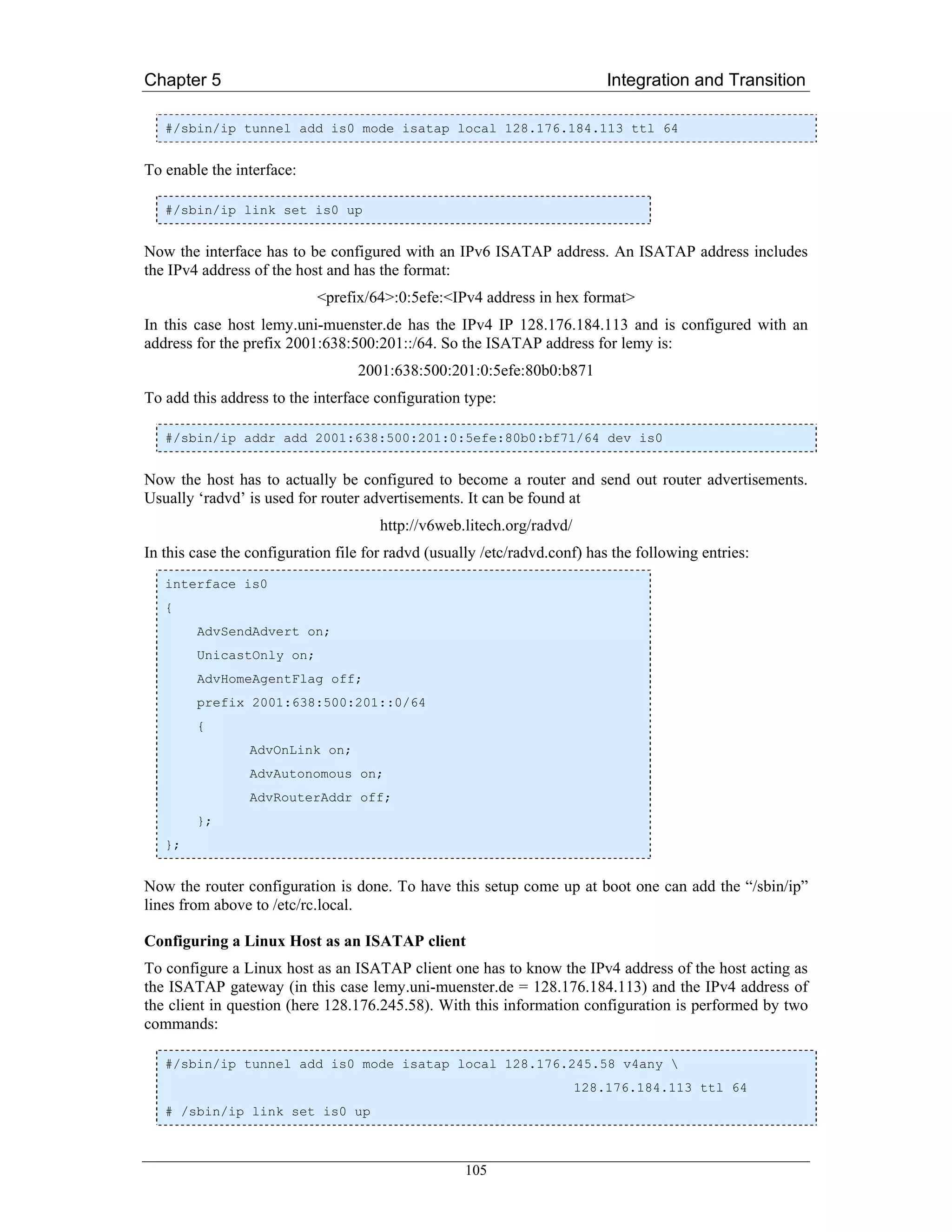
![Chapter 5 Integration and Transition
Now the client should be connected to the rest of the IPv6 world, as long as the ISATAP server has
global IPv6 connectivity.
5.5.5 OpenVPN Tunnel Broker
This following sections describe the process of setting up an OpenVPN based IPv6 tunnel broker to
enable ISP-independent IPv6 connectivity that is authenticated, secure, stable, and IPv4 source address
independent.
Though the OpenVPN client runs on many different platforms and hence a tunnel broker that is based
on OpenVPN should be able to accommodate quite a large number of different client OSes, this
section will only deal with Linux and Windows clients for now, since those are the client OSes that
haven been tested as tunnel broker clients.
5.5.5.1 Installation of Tunnel Broker components
To set up an OpenSSL certification authority it is sufficient to install the OpenSSL package on your
Linux distribution (check that the openssl-binary is present and executable as root). The more difficult
step is to create an appropriate configuration file and to create the necessary CA certificates and keys.
This section will present a sample openssl.cnf configuration file that is self explanatory and that may
be edited to fit individual needs. It will also list the necessary steps to create all CA keys and
certificates.
Installation of the OpenSSL CA
First, you need to create an openssl.cnf file. The following listing shows an example openssl.cnf that
was used for an OpenSSL CA:
#
# OpenSSL example configuration file.
#
HOME = .
RANDFILE = $ENV::HOME/.rnd
oid_section = new_oids
[ new_oids ]
[ ca ]
default_ca = CA_default
[ CA_default ]
dir = /usr/local/etc/openvpn/ssl # Adjust this!
certs = $dir
crl_dir = $dir
database = $dir/index.txt
new_certs_dir = $dir
106](https://image.slidesharecdn.com/ipv6deployment-guide-110112200202-phpapp01/75/IPv6-Deployment-Guide-120-2048.jpg)
![Chapter 5 Integration and Transition
certificate = $dir/tmp-ca.crt # Adjust this!
serial = $dir/serial
crl = $dir/crl.pem
private_key = $dir/tmp-ca.key # Adjust this!
RANDFILE = $dir/.rand
x509_extensions = usr_cert
name_opt = ca_default
cert_opt = ca_default
default_days = 365 # Adjust this!
default_crl_days= 30
default_md = md5
preserve = no
policy = policy_match
[ policy_match ]
countryName = match
stateOrProvinceName = match
organizationName = match
organizationalUnitName = optional
commonName = supplied
emailAddress = optional
[ policy_anything ]
countryName = optional
stateOrProvinceName = optional
localityName = optional
organizationName = optional
organizationalUnitName = optional
commonName = supplied
emailAddress = optional
[ req ]
default_bits = 1024
default_keyfile = privkey.pem
distinguished_name = req_distinguished_name
attributes = req_attributes
x509_extensions = v3_ca
string_mask = nombstr
[ req_distinguished_name ]
107](https://image.slidesharecdn.com/ipv6deployment-guide-110112200202-phpapp01/75/IPv6-Deployment-Guide-121-2048.jpg)
![Chapter 5 Integration and Transition
countryName = Country Name (2 letter code)
countryName_default = DE # Adjust this!
countryName_min = 2
countryName_max = 2
stateOrProvinceName = State or Province Name (full name)
stateOrProvinceName_default = Nordrhein-Westfalen # Adjust this!
localityName = Locality Name (eg, city)
localityName_default = Muenster # Adjust this!
0.organizationName = Organization Name (eg, company)
0.organizationName_default = ZIV, WWU Muenster # Adjust this!
organizationalUnitName = Organizational Unit Name (eg, section)
organizationalUnitName_default = JOIN-Projekt # Adjust this!
commonName = Common Name (eg, YOUR name)
commonName_max = 64
emailAddress = Email Address
emailAddress_max = 64
[ req_attributes ]
challengePassword = A challenge password
challengePassword_min = 4
challengePassword_max = 20
unstructuredName = An optional company name
[ usr_cert ]
basicConstraints=CA:FALSE
nsComment = “OpenSSL Generated Certificate”
subjectKeyIdentifier=hash
authorityKeyIdentifier=keyid,issuer:always
[ v3_req ]
basicConstraints = CA:FALSE
keyUsage = nonRepudiation, digitalSignature, keyEncipherment
[ v3_ca ]
subjectKeyIdentifier=hash
108](https://image.slidesharecdn.com/ipv6deployment-guide-110112200202-phpapp01/75/IPv6-Deployment-Guide-122-2048.jpg)
![Chapter 5 Integration and Transition
authorityKeyIdentifier=keyid:always,issuer:always
basicConstraints = CA:true
[ crl_ext ]
authorityKeyIdentifier=keyid:always,issuer:always
Please note that you need to include “-config openssl.cnf” (where openssl.cnf is to be given with full
path if not located in current directory) in every call of the openssl-binary.
Also note that you must initialise the files index.txt and serial when setting up the CA. You can create
index.txt as an empty file and serial with the content “01”. Additionally, you need a DH-hash that you
can create with the command
#openssl dhparam -out /usr/local/etc/openvpn/ssl/dh1024.pem 1024
After creating the openssl.cnf file you must then create the keys and certificates for your CA.
It is important to note that this section shows a rather lax use of a CA. Ideally, you should take the
process of running a CA rather seriously, especially if you want to hold people liable for the abuse of
your tunnel broker. If you already have an established CA, please try to use it for creating client and
server certificates. This will add to the security of your tunnel broker. Please use “your own private
little CA” just for experimental purposes or if you think that you can afford to keep the security rather
lax.
To create your own CA keys and certificates, run the following command:
# openssl req -days 365 -new -x509 -keyout tmp-ca.key
-out tmp-ca.crt -config openssl.cnf
This command will create the secret key called “tmp-ca.key” and the certificate “tmp-ca.crt”. Please
note that the notation “tmp-ca.*” is intentional to make administrators aware that they are dealing with
an experimental or temporary CA. Please make sure that the permissions for the secret key do not
allow it to be read by any other user than the one who created it (“chmod 600 tmp-ca.key”).
With these basic steps the setup of the OpenSSL CA is completed.
Installation of the OpenVPN server
At the time this was written, a very recent CVS version of the OpenVPN software was needed to have
all functionality that was necessary for running the OpenVPN based IPv6 tunnel broker. The
OpenVPN software can be found at
http://openvpn.sourceforge.net/
Please follow the installation instructions for the CVS version on the OpenVPN site. The installation is
not expected to pose any problems.
It is assumed that the OpenVPN sources are compiled with the given installation prefix /usr/local
which means that the configuration files can be found in /usr/local/etc/openvpn. Naturally, any other
prefix works just as well but for the sake of readability, the /usr/local prefix will be used for the
remainder of this section.
109](https://image.slidesharecdn.com/ipv6deployment-guide-110112200202-phpapp01/75/IPv6-Deployment-Guide-123-2048.jpg)
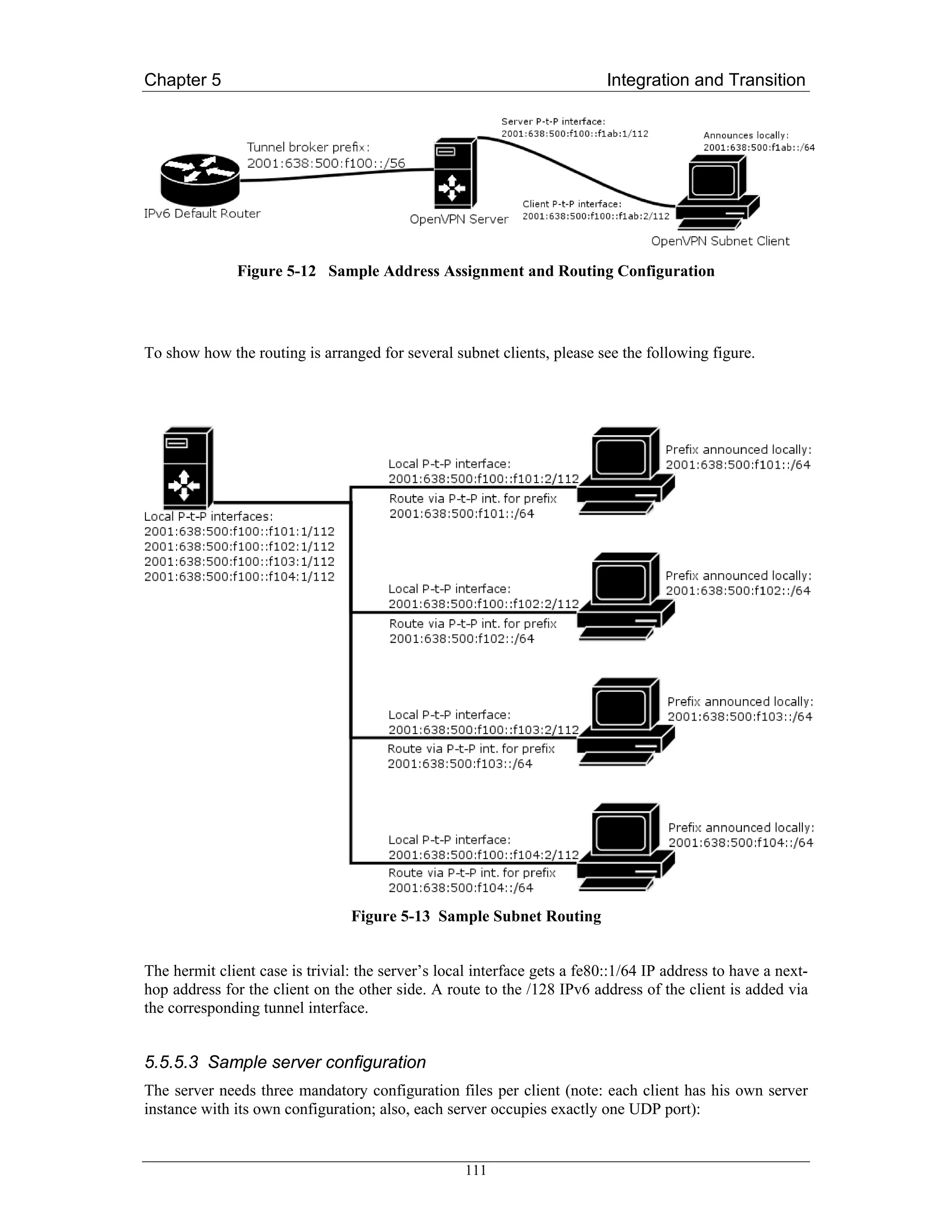
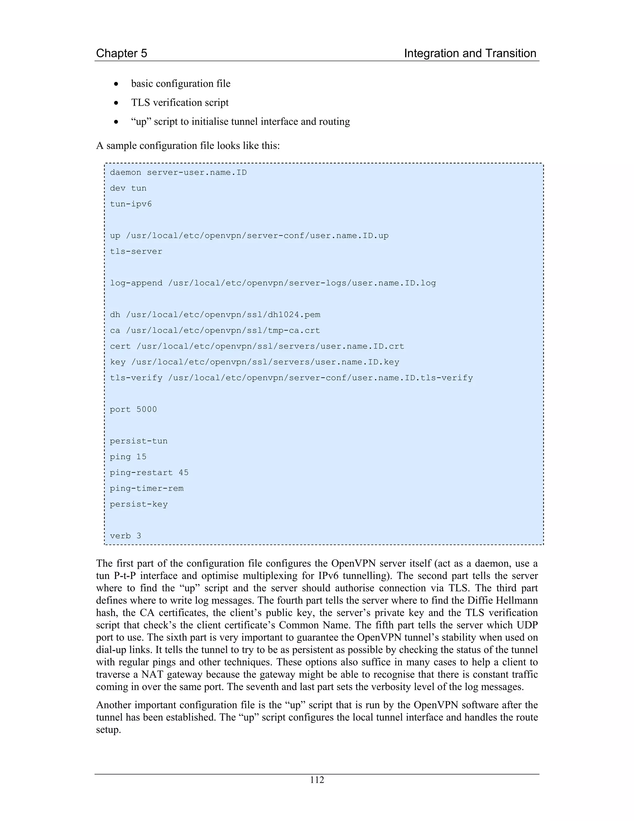
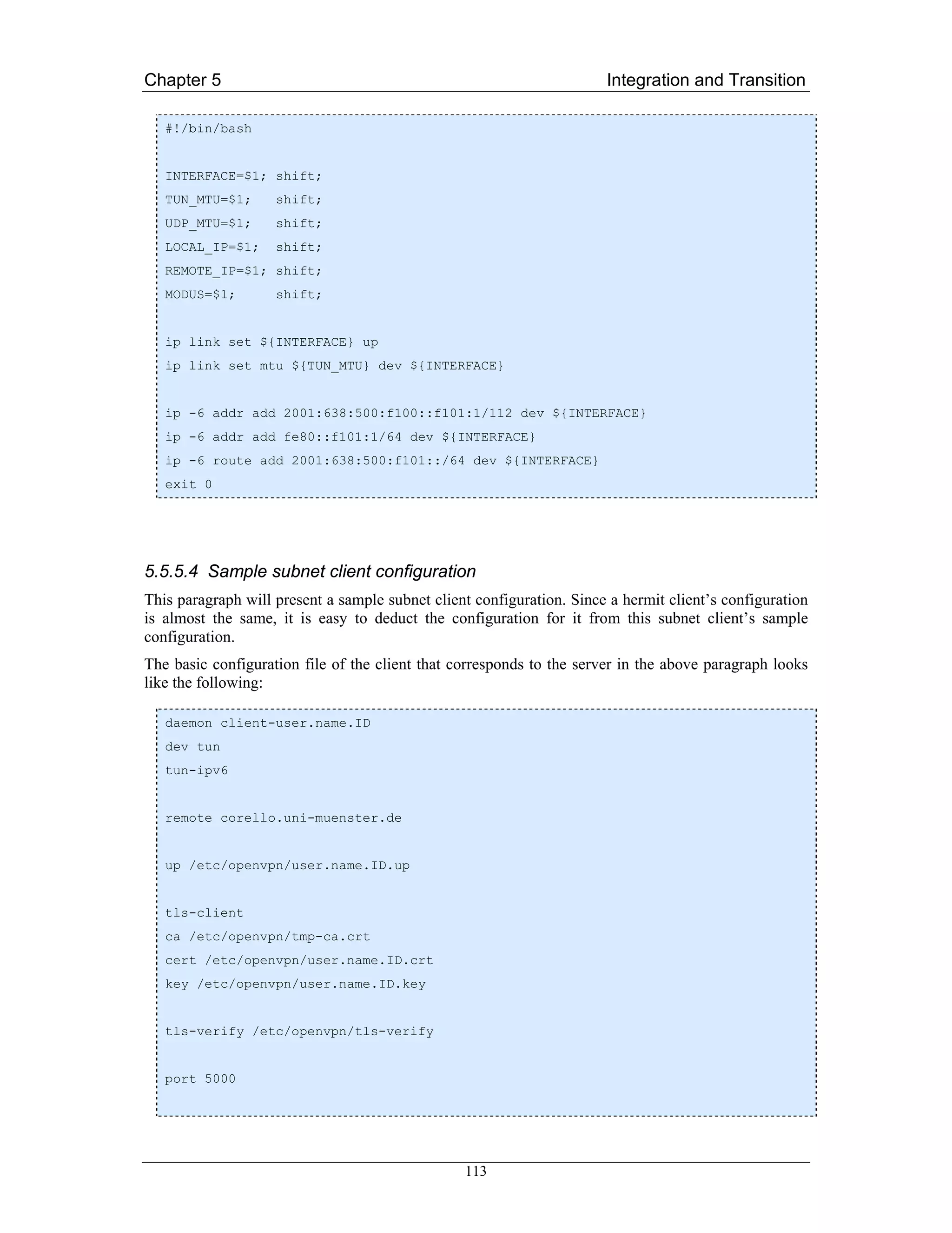
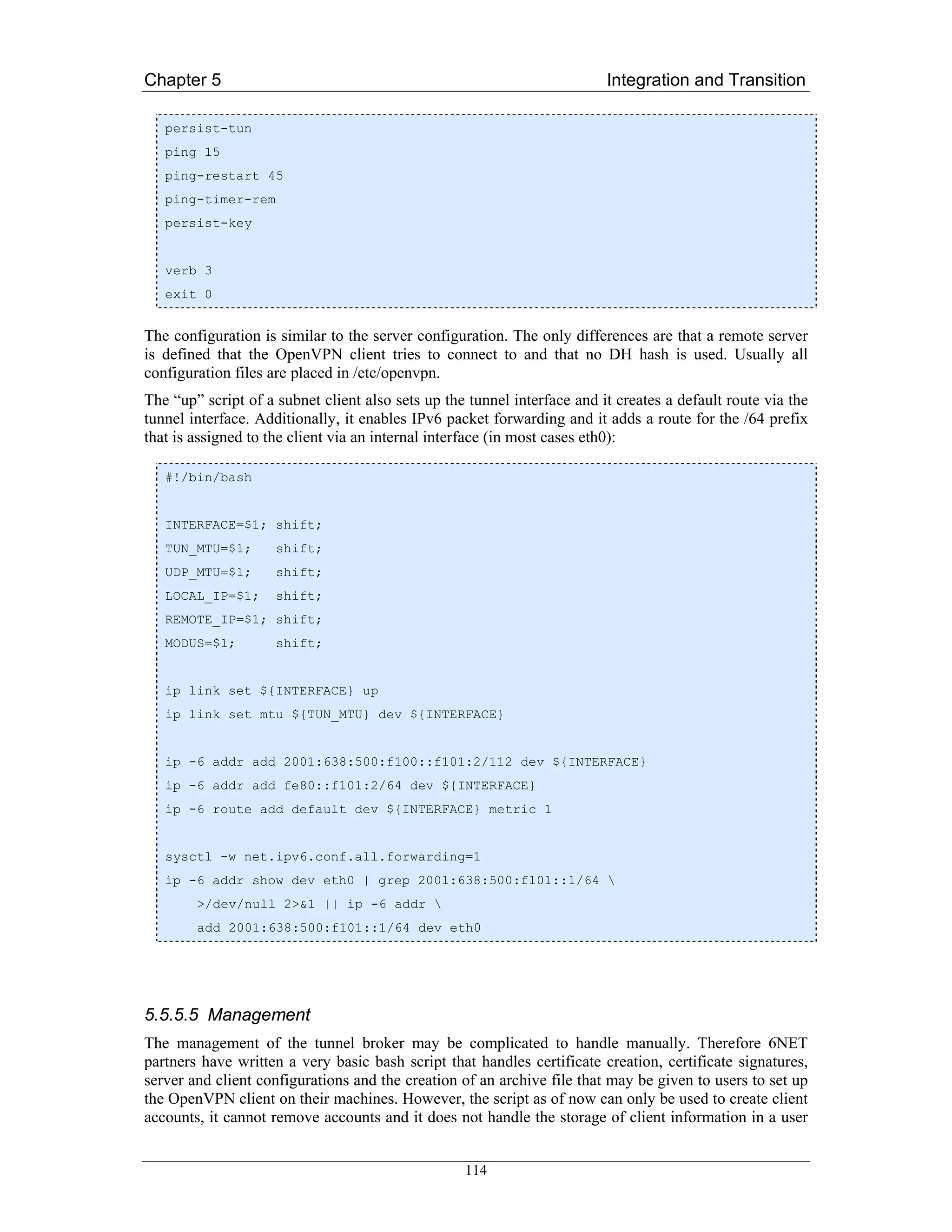
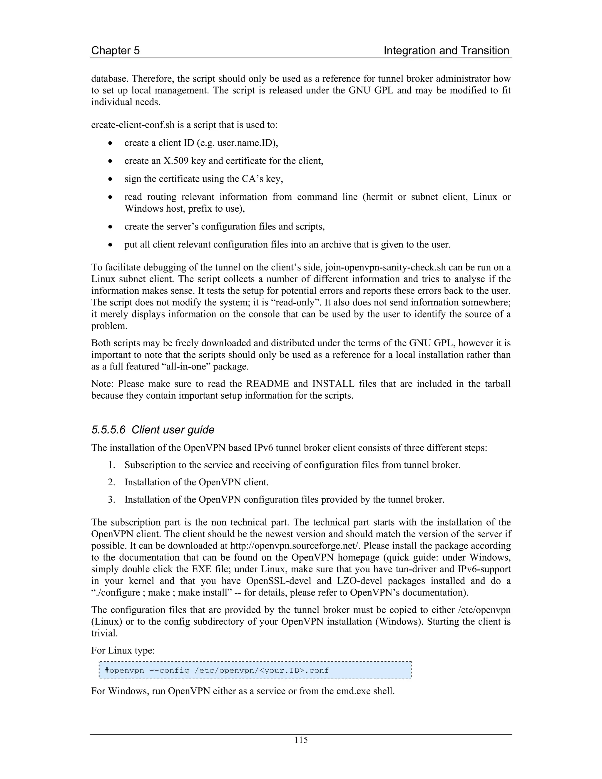
![Chapter 5 Integration and Transition
5.5.6 DSTM
5.5.6.1 A DSTM Experiment with FreeBSD 4.5
The DSTM server/TEP implementation by ENST [ENST] is available on the ENST’s web site:
http://www.ipv6.rennes.enst-bretagne.fr/dstm/
The implementation requires that the server and gateway (TEP) be installed on the same host if the
allocations made by the server should be coherent with the tunnels set up on the TEP. An external TEP
(For example a 6Wind router with DSTM code) can also be used (But, this scenario has not been
tested). In that case the TEP manages the tunnels directly and does not interact with the server, which
then only is responsible for distributing the leases of IPv4 addresses. It must only be insured that the
leases expire/renew durations are coherent with respect to the TEP configuration. In this configuration
example however the TEP and the server are the same program. Thus the tunnel extremities are on the
machine running the server and there is no way to use two different Linux/FreeBSD nodes separating
the server from the TEP.
Figure 5-14 Test Network Infrastructure
When installing DSTM one has to be aware of the fact that the TEP has to be the router declared as
having access to the IPv4 address pool from the IPv4 world, and that the DSTM server program does
not manage route advertisements. Therefore, on the server site, one must provide by some way routes
and route advertisements for the IPv4 addresses of DSTM clients toward the TEP node. For example
on the site entry router, one can set a route for the remote IPv4 address pool allocated to DSTM clients
toward the TEP IPv4 address, and make sure that this IPv4 route is announced or aggregated. Also
there are routing loops between the TEP and the site IPv4 default router thus, on the TEP node; one
should set a static discard route to suppress all traffic to down clients.
The DSTM implementation uses RPCv6, TSP and TSP–SSL (For VPN scenario) for the
communication between DSTM Server/TEP and DSTM clients. Until now, the current implementation
has no support for DHCPv6
116](https://image.slidesharecdn.com/ipv6deployment-guide-110112200202-phpapp01/75/IPv6-Deployment-Guide-130-2048.jpg)
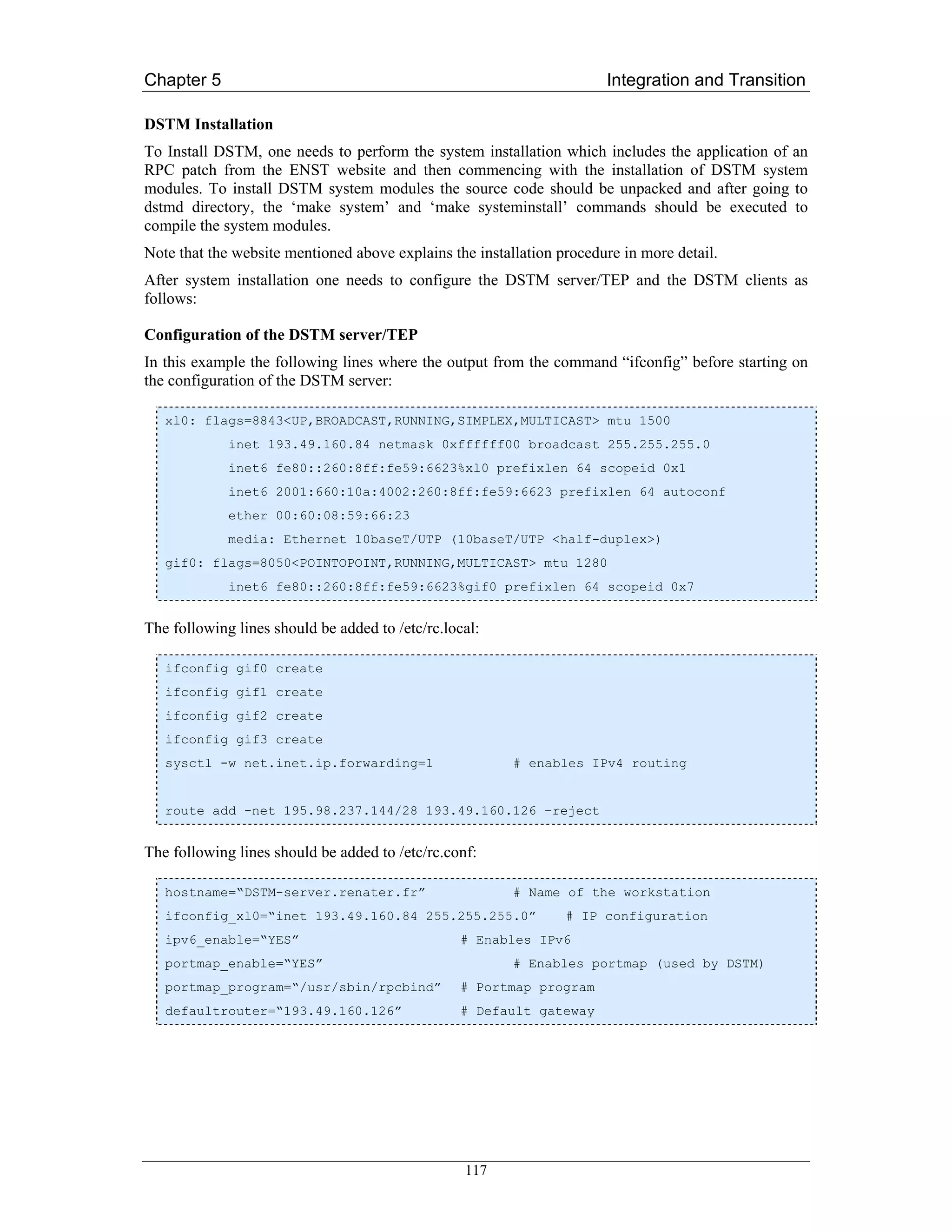
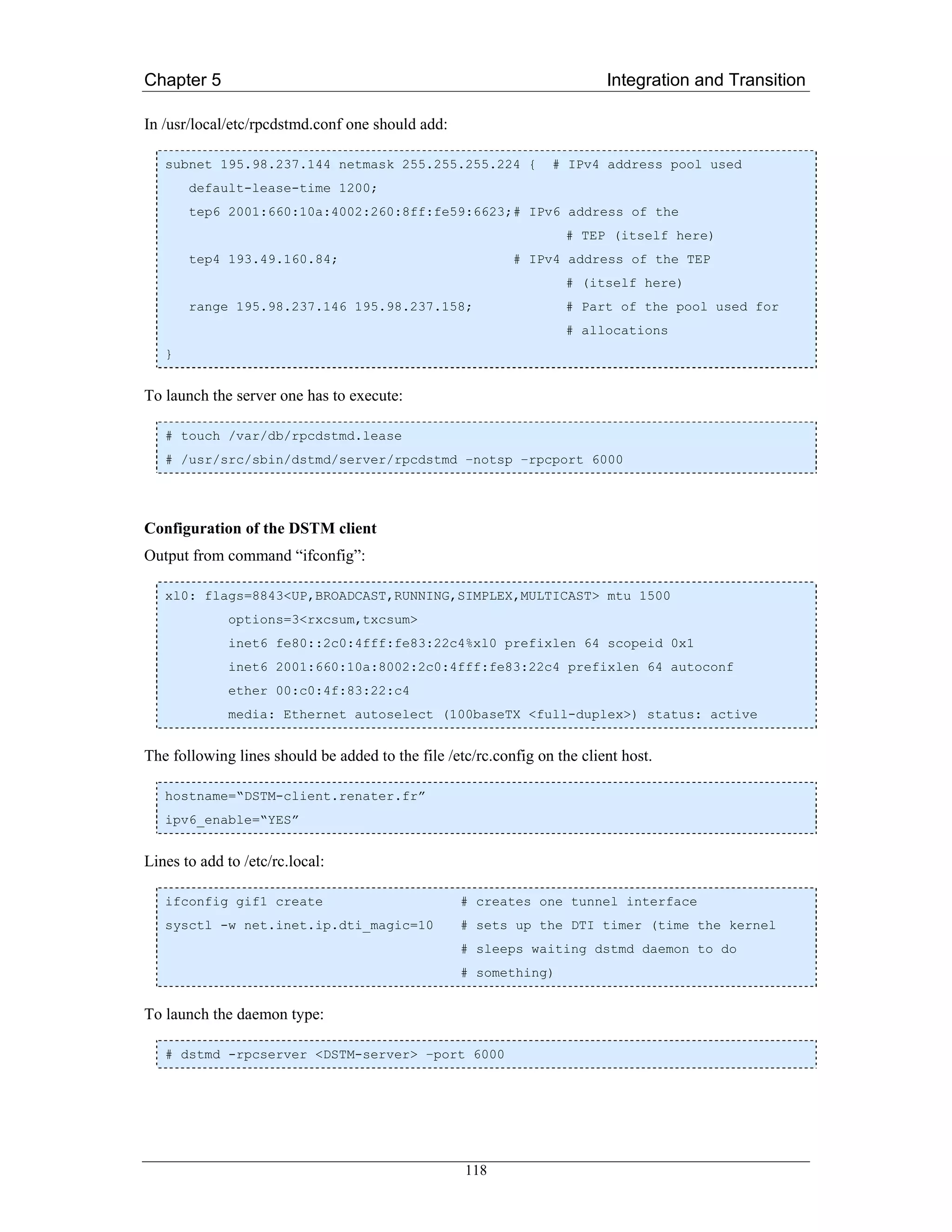
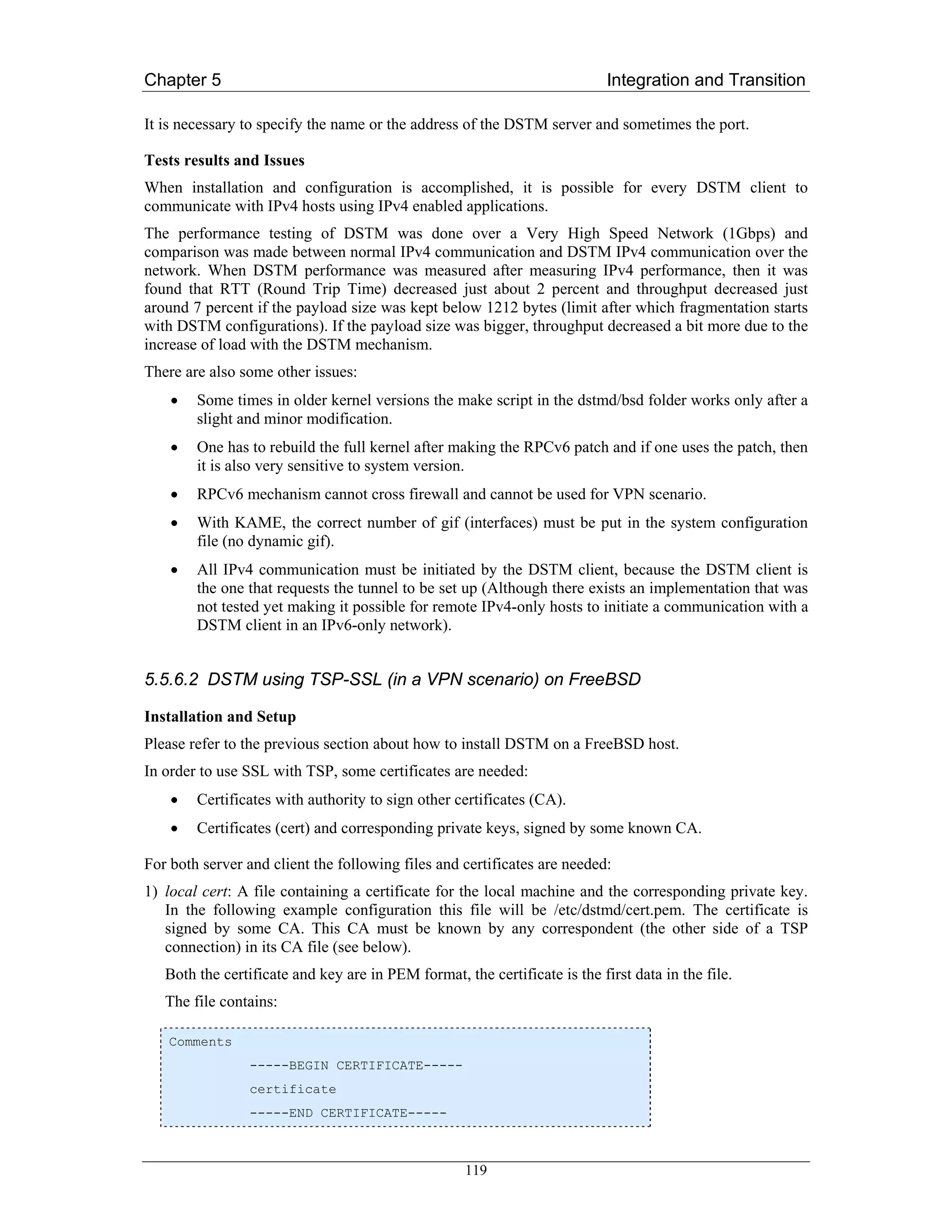
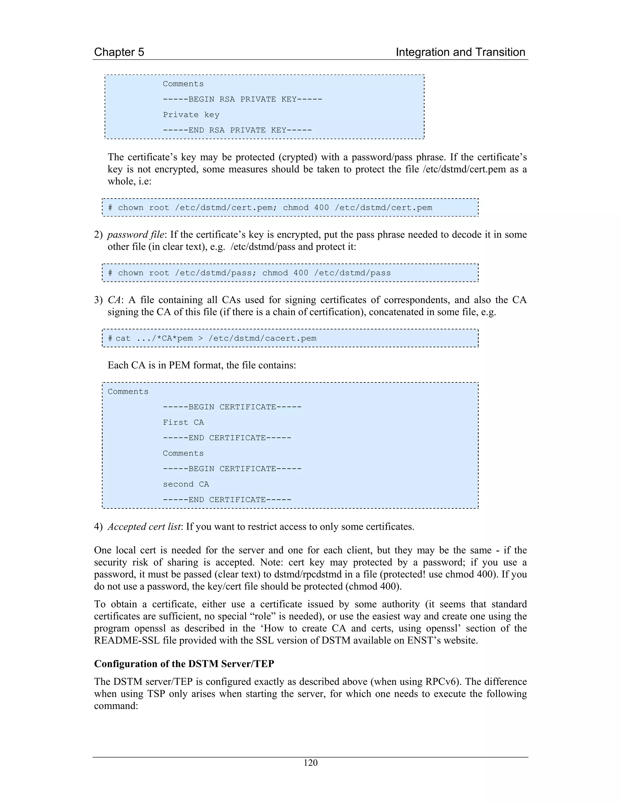
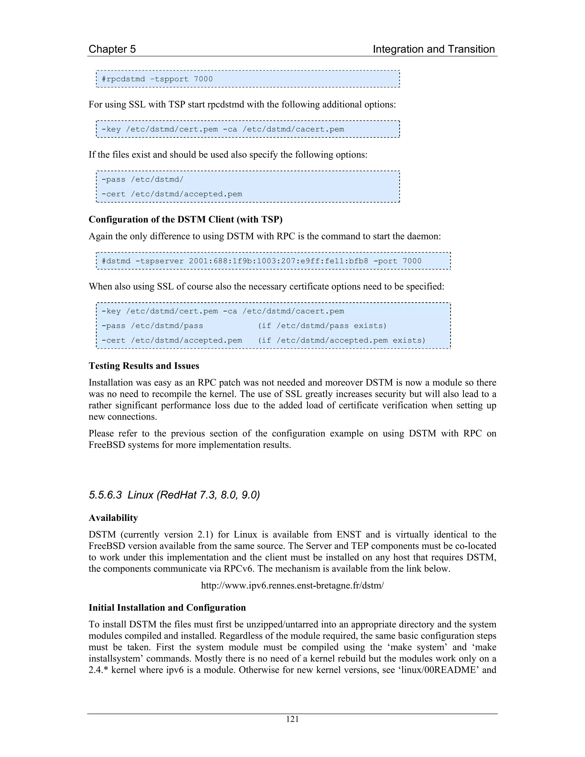
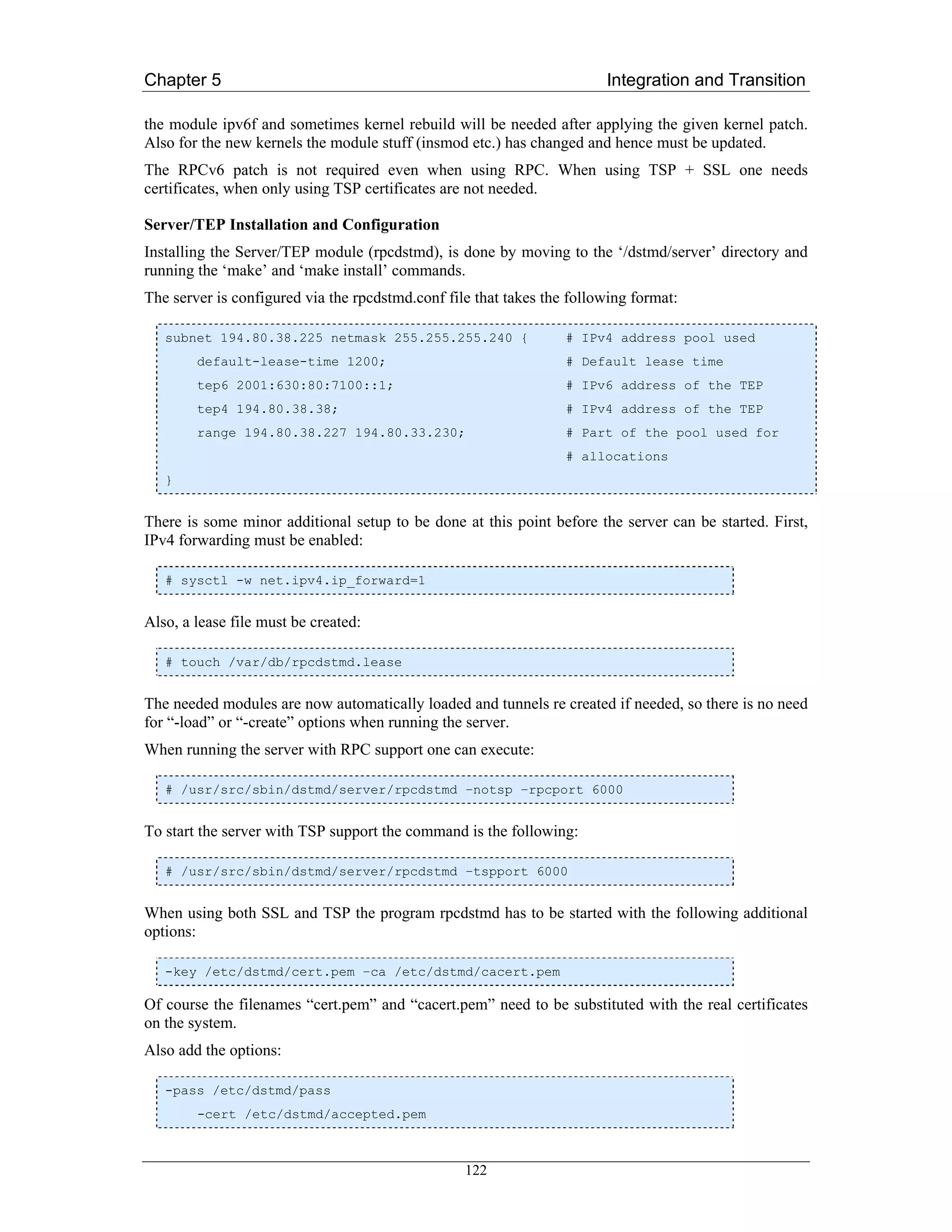
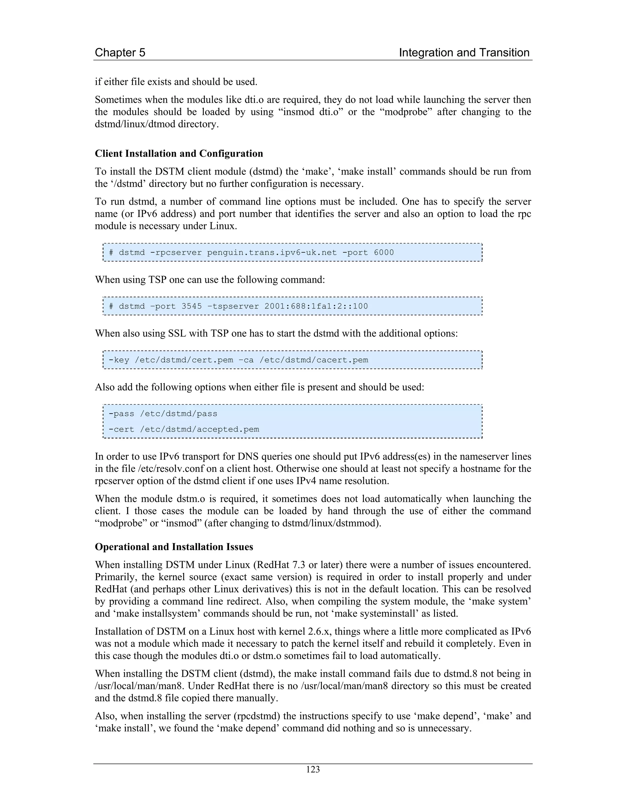
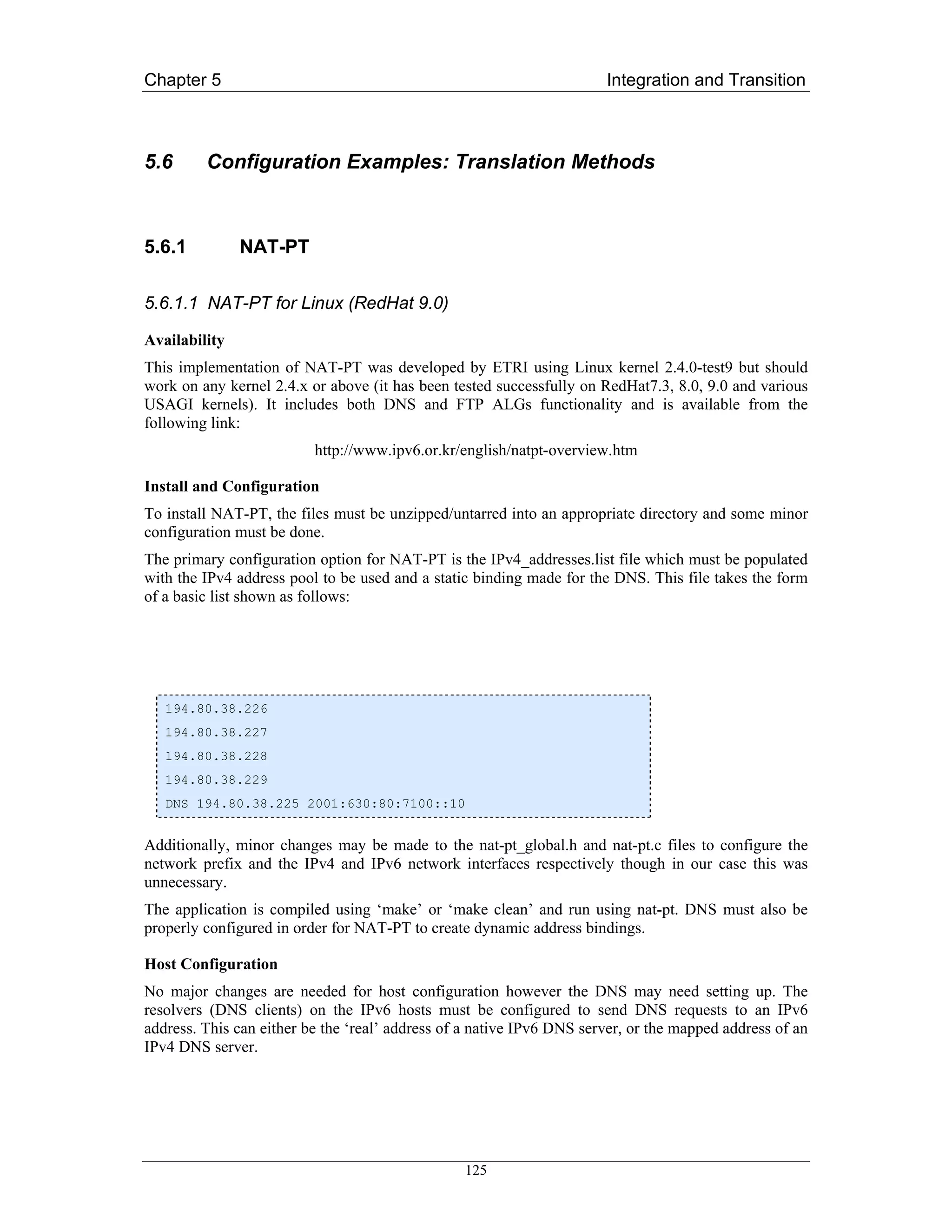
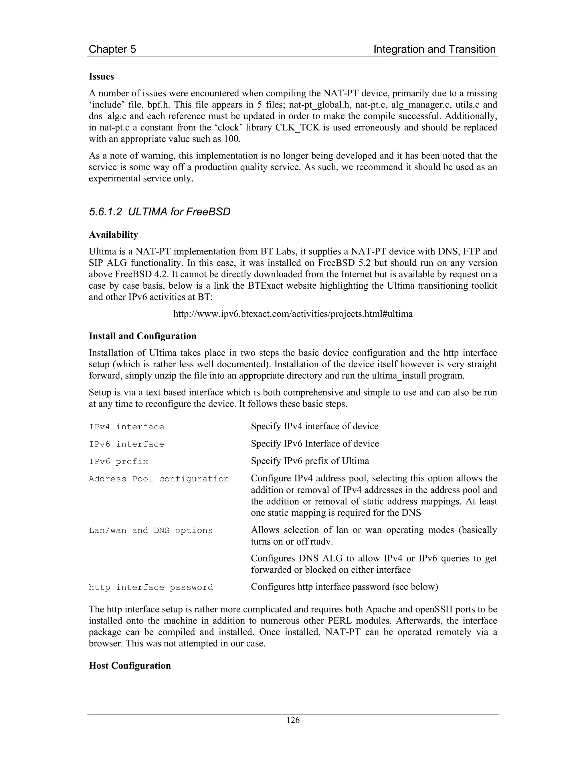
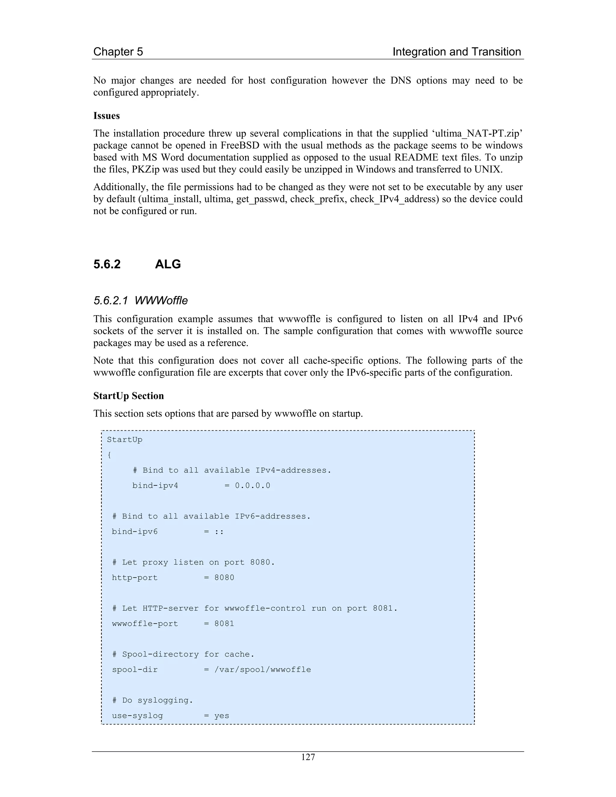
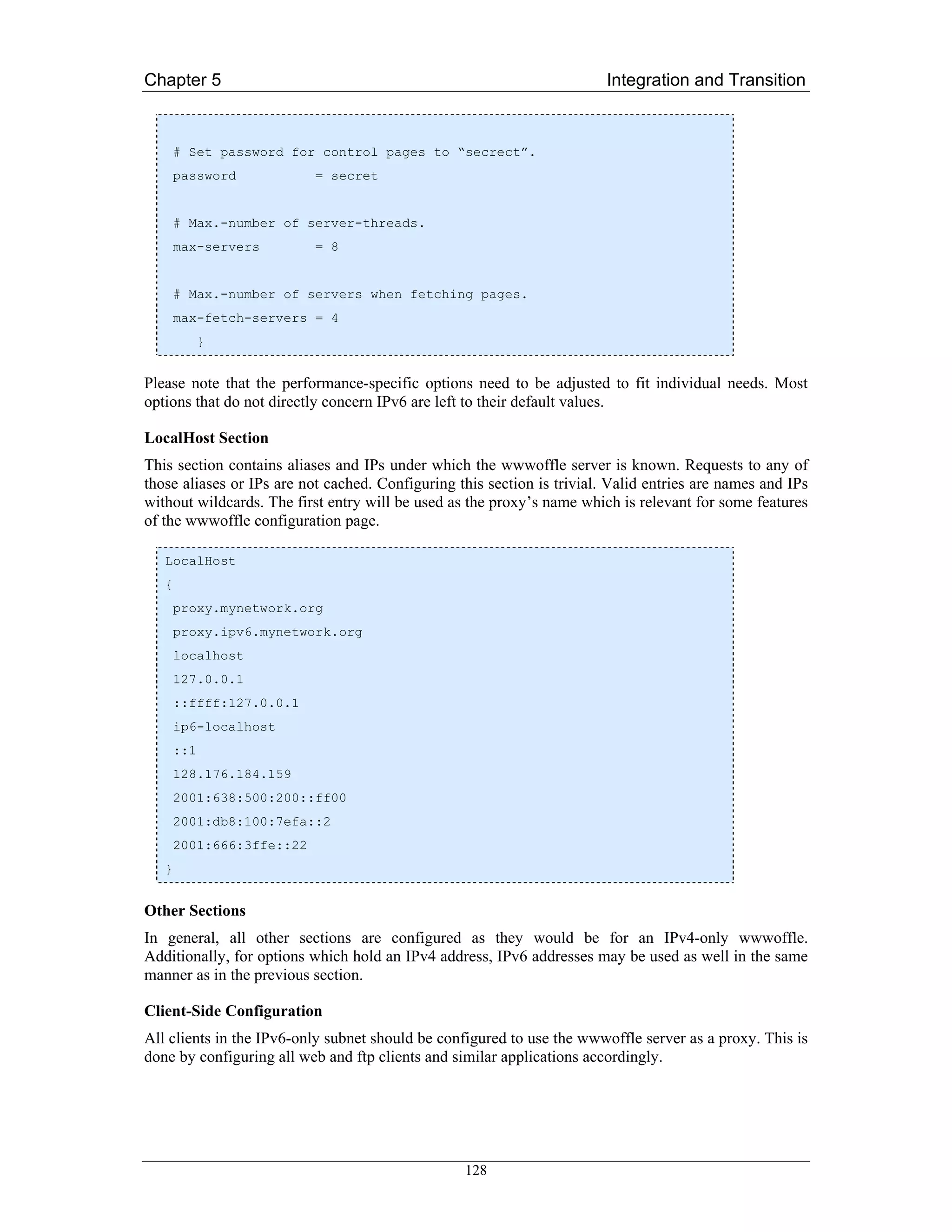
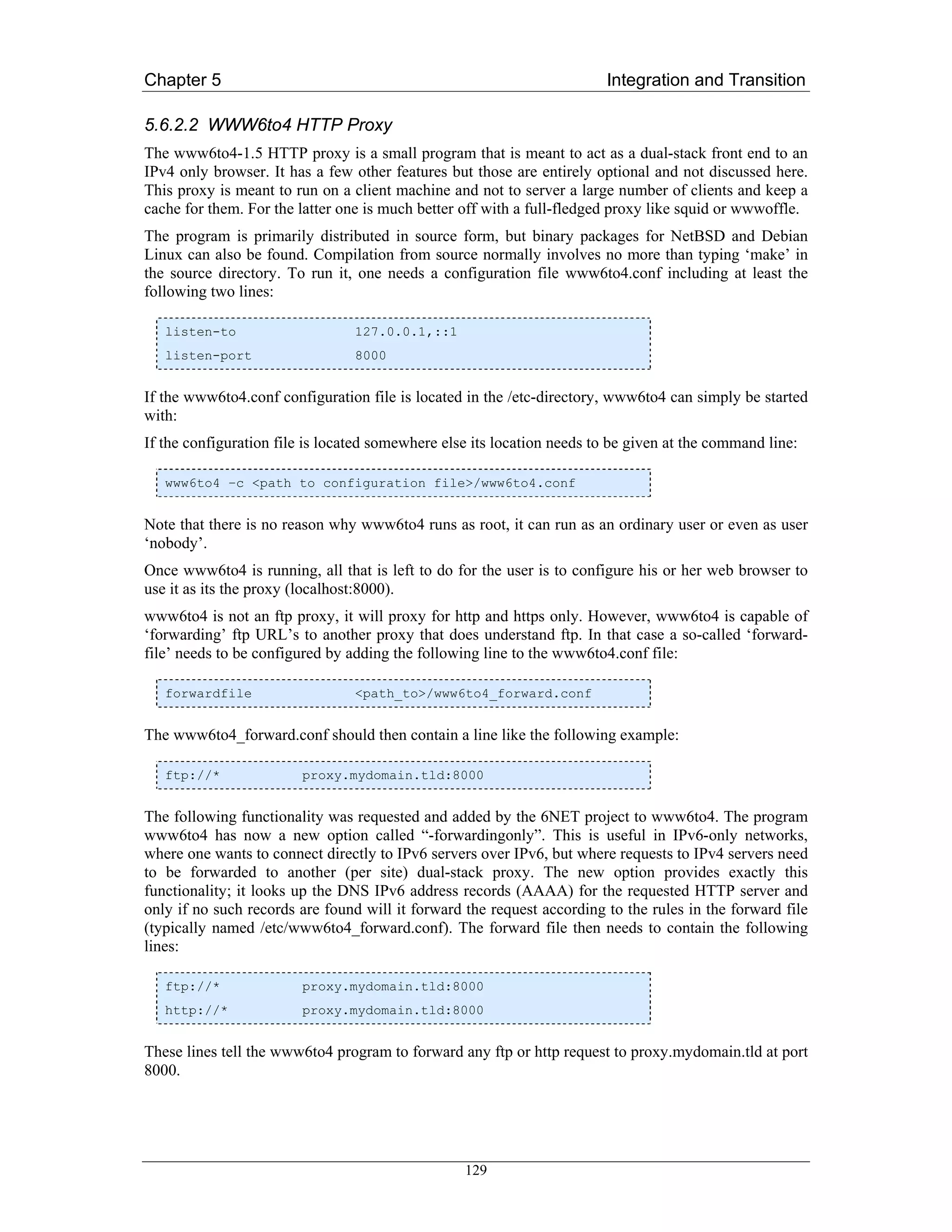
![Chapter 5 Integration and Transition
5.6.2.3 Postfix Configuration
Server side configuration
In most cases, postfix’ configuration files are located in /etc/postfix. Basically, only the file main.cf
needs to be modified. When modifying main.cf, it is important to be aware of potential security risks
that may occur if these modifications are not done carefully. One should under all circumstances avoid
creating open relays that allow spam and bulk mailers to abuse the ALG as a relay server.
To be able to relay mail from the IPv6-only subnet, this subnet has to be added to the trusted subnets
(the class of subnets that are allowed to relay mail via this server). By default, postfix trusts all
machines that are in the same subnet as the postfix server. This behaviour is configured by setting
mynetworks_style = subnet
in main.cf. We assume that the IPv6-only subnet has the prefix 2001:db8:10:110::/64. To allow hosts
in this subnet to relay via this postfix server, we add the prefix to “mynetworks” in main.cf.
mynetworks = [2001:638:500:200::]/64, [2001:db8:10:110::]/64,
[::1]/128, 127.0.0.0/8
Note that in this case, 2001:638:500:200::/64 is the subnet that the postfix server is located in.
Using the two options above allows relaying from the IPv6-only subnet for which the postfix server
acts as an ALG.
Client Side Configuration
The postfix server above may be used as a normal SMTP server by any email clients in the IPv6-only
subnet. This has to be configured for each application separately.
Mail Transfer Applications (MTAs)
MTAs such as postfix and sendmail can be configured to use an SMTP smarthost. In postfix’s case,
this is done by adding the following option to main.cf:
relayhost = [2001:638:500:200:0:0:0:ff00:25]
This lets postfix relay all outgoing mail via 2001:638:500:200::ff00:25. 2001:638:500:200::/64 is the
subnet that the postfix server is located in.
Using the two options above allows relaying from the IPv6-only subnet for which the postfix server
acts as an ALG. This is a save configuration in terms of relay protection as long as only the IPv6-only
subnet is allowed to use the postfix server as a relaying smarthost.
5.6.2.4 SMTP Relaying with Sendmail
From IPv6 to IPv4
One can set up a single dual-stack mail server to act as a so called ‘smart host’ (smart mail relay) for
IPv6-only hosts. A sendmail configuration file ‘sendmail.cf’ is typically generated from an m4 macro
file. One should add the following lines to this m4 macro file:
DAEMON_OPTIONS(`Family=inet, address=0.0.0.0, Name=MTA')dnl
DAEMON_OPTIONS(`Family=inet6, address=::, Name=MTA6, Modifiers=O')dnl
130](https://image.slidesharecdn.com/ipv6deployment-guide-110112200202-phpapp01/75/IPv6-Deployment-Guide-144-2048.jpg)
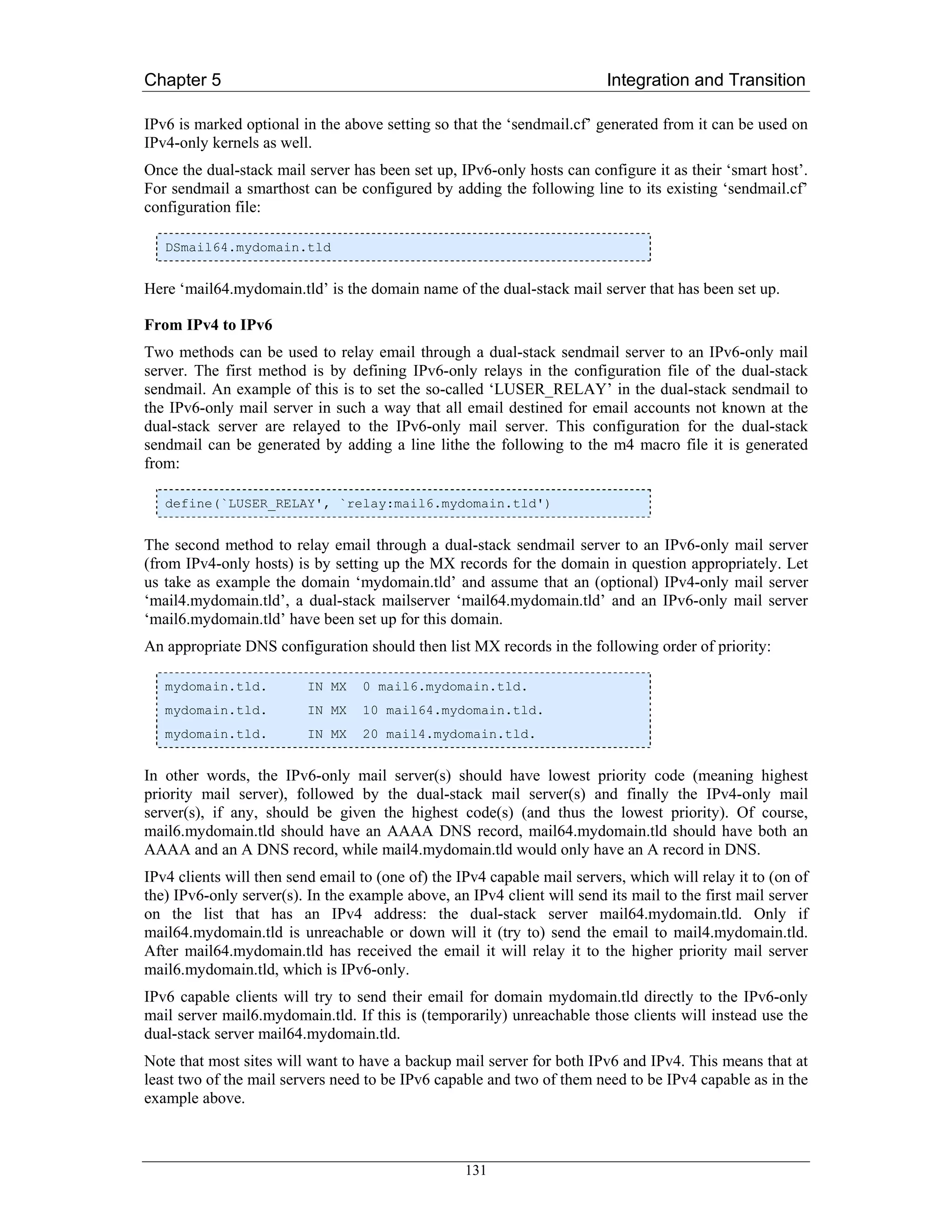
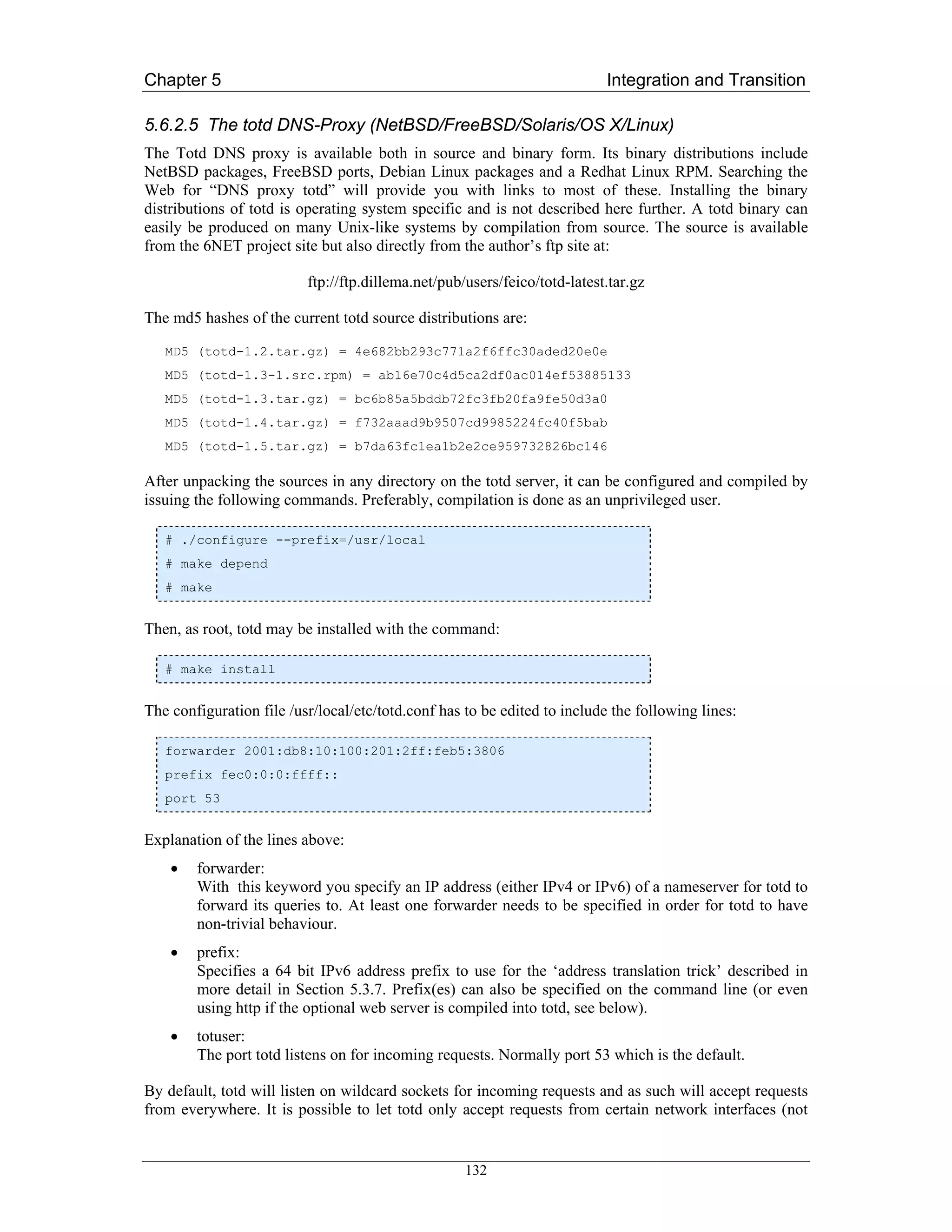
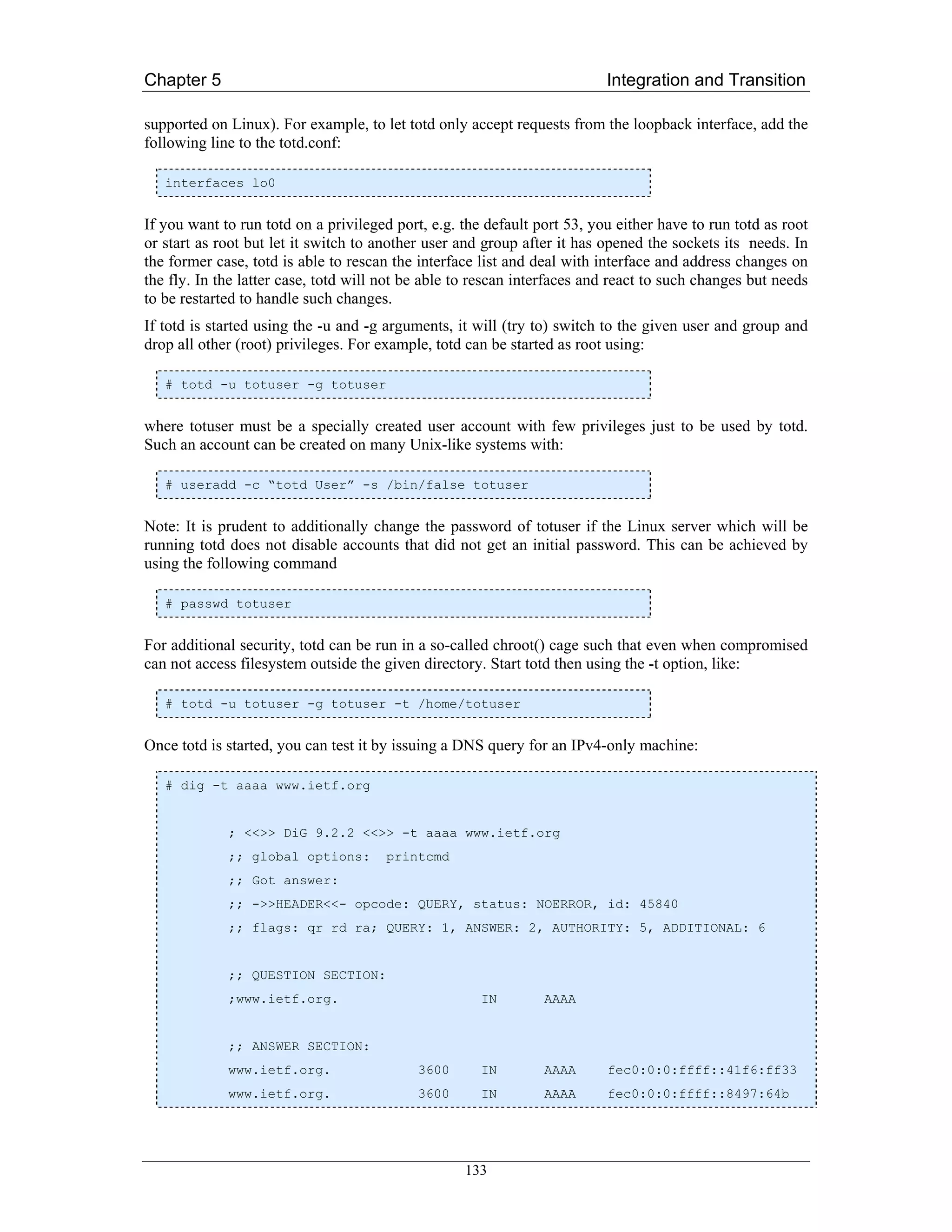
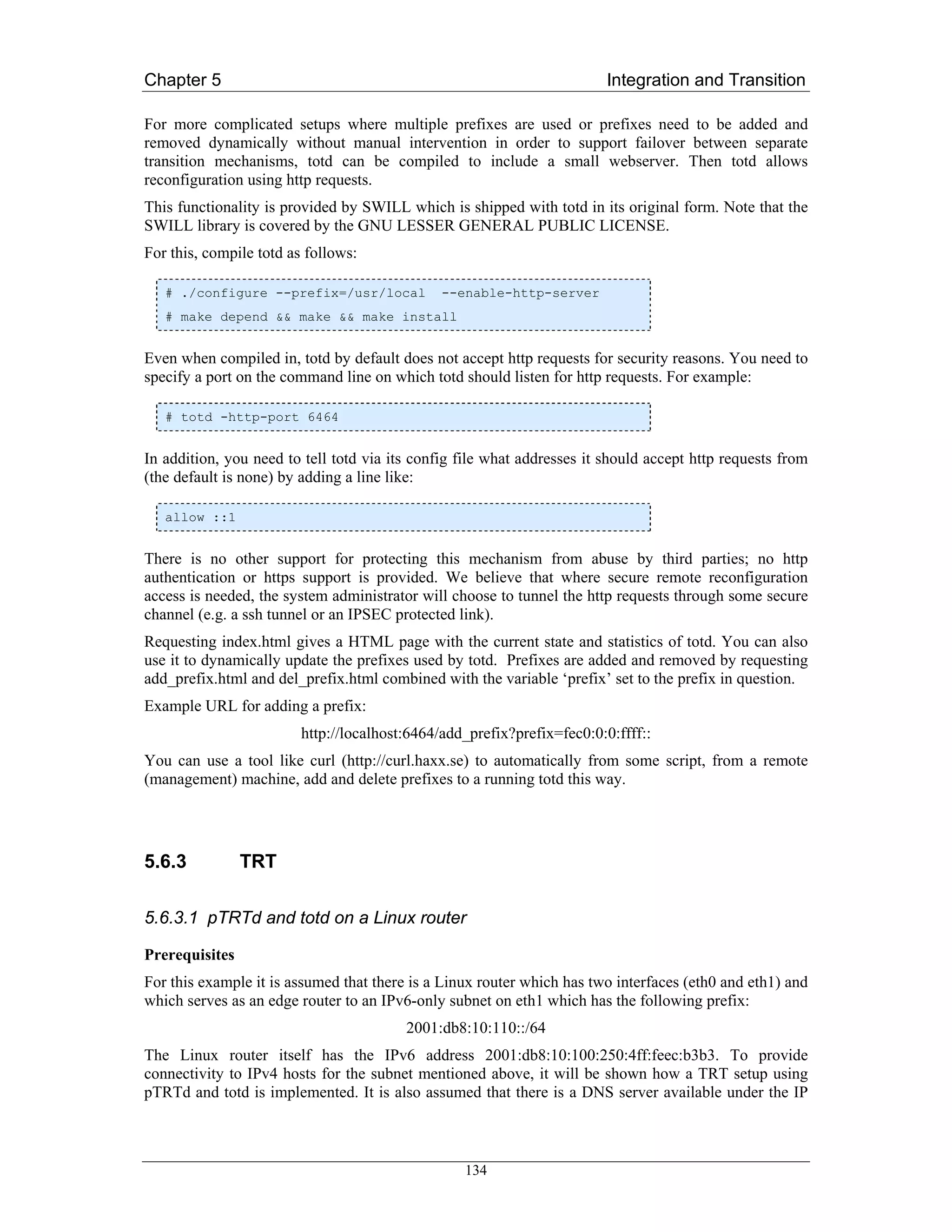
![Chapter 5 Integration and Transition
2001:db8:10:100:201:2ff:feb5:3806. This server will be used to resolve DNS queries done by clients
with IPv6-only connectivity and forwarded by totd.
Overview of installation steps
The following steps summarize the configuration work that has to be performed to provide TRT
functionality on the Linux router for the 2001:db8:10:110::/64 subnet:
• Installation of totd on a dedicated host. Not that this host does not necessarily have to be a
dual-stack host nor does it have to be the same host that pTRTd will run on.
• Configuration of totd to use existing DNS and to prepend a specific prefix to converted IPv4
addresses.
• Starting totd.
• Check that all prerequisites for the installation of pTRTd on the Linux router are met.
• Installation of pTRTd and starting it.
Installation of totd
Totd does not necessarily need to be installed on a dual-stack host or on the (Linux/Unix flavour)
router that will be running pTRTd. However, the server hosting totd has to have IPv6-connectivity
because it has to be reachable from an IPv6-only subnet. If there is an IPv6 capable DNS available to
the totd sever, there is no need for it to have IPv4 connectivity. Otherwise, IPv4 connectivity is needed
for contacting a DNS with only an IPv4 stack.
Installation of pTRTd
There are a few requirements that have to be fulfilled before pTRTd can be used:
• tun/tap driver support needs to be present in the Linux kernel (Version 2.2 or higher) either as
a module or compiled into the kernel itself.
• A working totd server has to be present to provide translated IPv4 addresses. Totd has to be
configured to prepend the prefix fec0:0:ffff:: to converted IPv4 addresses. Note that
fec0:0:ffff:: is a site-local prefix. It may not make sense to use global prefixes. Please also
note, that site-local prefixes are deprecated meanwhile. We keep this language here for the
sake of consistency.
• /sbin/ip has to be present to allow pTRTd to set up an interface and a route.
Compilation and installation of pTRTd is trivial. After unpacking the sources on the Linux router,
configuration and compilation of pTRTd is done by issuing the following commands:
# ./configure --prefix=/usr/local
# make
As root, pTRTd may be installed to /usr/local by running:
# make install
The usage of pTRTd is as follows:
# ptrtd [-i [<driver>:]<interface>] [-p <prefix>] [-l <prefix length>]
135](https://image.slidesharecdn.com/ipv6deployment-guide-110112200202-phpapp01/75/IPv6-Deployment-Guide-149-2048.jpg)
![Chapter 5 Integration and Transition
<prefix> defaults to fec0:0:0:ffff::/64 which means that there is no need to give the “-p” option if totd
was configured to use this prefix. In general, there should be no need to give any options when starting
pTRTd if TRT is set up according to this description. PTRTd is run by simply starting the daemon:
# /usr/local/sbin/ptrtd
If possible, one should perform a few checks to see whether or not pTRTd came up properly:
• “ps -ef | grep ptrtd” shows whether pTRTd is indeed up and running.
• “ip link show” verifies that a tap0 interface came up after starting pTRTd.
• “ip route show” checks whether or not there is a route which routes fec0:0:0:ffff::/64 via the
tat0 interface mentioned above.
Configuring clients in the IPv6-only subnet
It is necessary to configure all clients in the IPv6-only subnet to use the totd server as DNS or
otherwise no proper translation of IPv4 addresses is done.
To test the configuration, one can use an IPv6 enabled application and try to contact a server that is
normally only reachable via IPv4, e.g. start an IPv6 capable browser like Mozilla and point it to a web
server that only has an IPv4 address. Ideally, the browser is configured not to use any proxies for
testing purposes. If it still can display the pages served by the IPv4-only server, the TRT installation
was successful.
5.6.3.2 NTPD Time Server as a Proxy
Latest versions of the ntpd time server support IPv6. Building, installing and configuring ntpd with
IPv6 support requires nothing special; it will simply listen for requests over both IPv4 and IPv6 and it
can talk to either IPv4 or IPv6 ntpd servers.
5.6.3.3 The Faith TRT for FreeBSD and NetBSD
The transport relay translator faithd [RFC3142] is an IPv6-to-IPv4 TCP relay. Faithd relays TCP (not
UDP, RTP or other transport protocols) from IPv6 to IPv4 (not the other way around). The faith
daemon needs to be run on a dual-stack router between you local IPv6 site and outside IPv4 network.
The daemon needs to be invoked per TCP service (TCP port number).
Example Setup
This example setup consists of two hosts on the same link running NetBSD software which are
connected to a gateway. One of the hosts will be the TCP translator of the connections that the other
host tries to establish. Once the TCP translation has been performed, the TCP connection will follow
the normal way through the gateway.
136](https://image.slidesharecdn.com/ipv6deployment-guide-110112200202-phpapp01/75/IPv6-Deployment-Guide-150-2048.jpg)
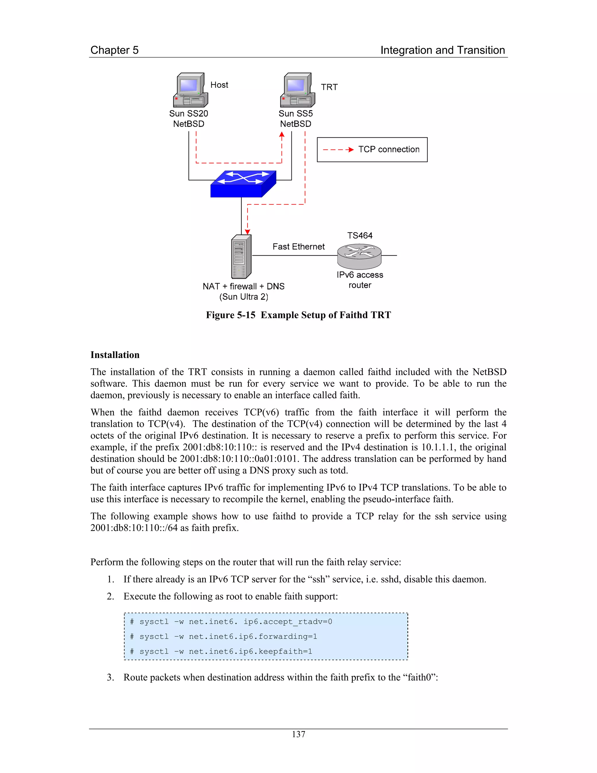
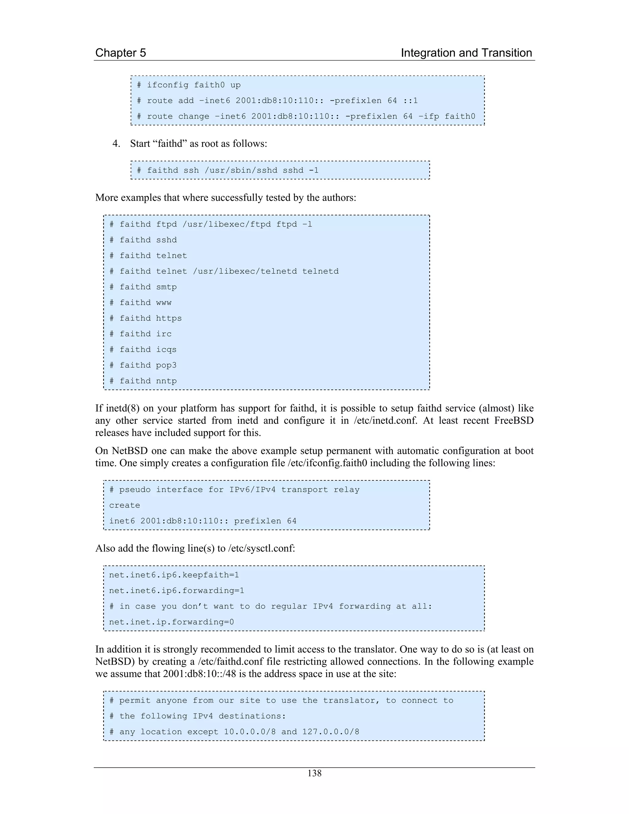
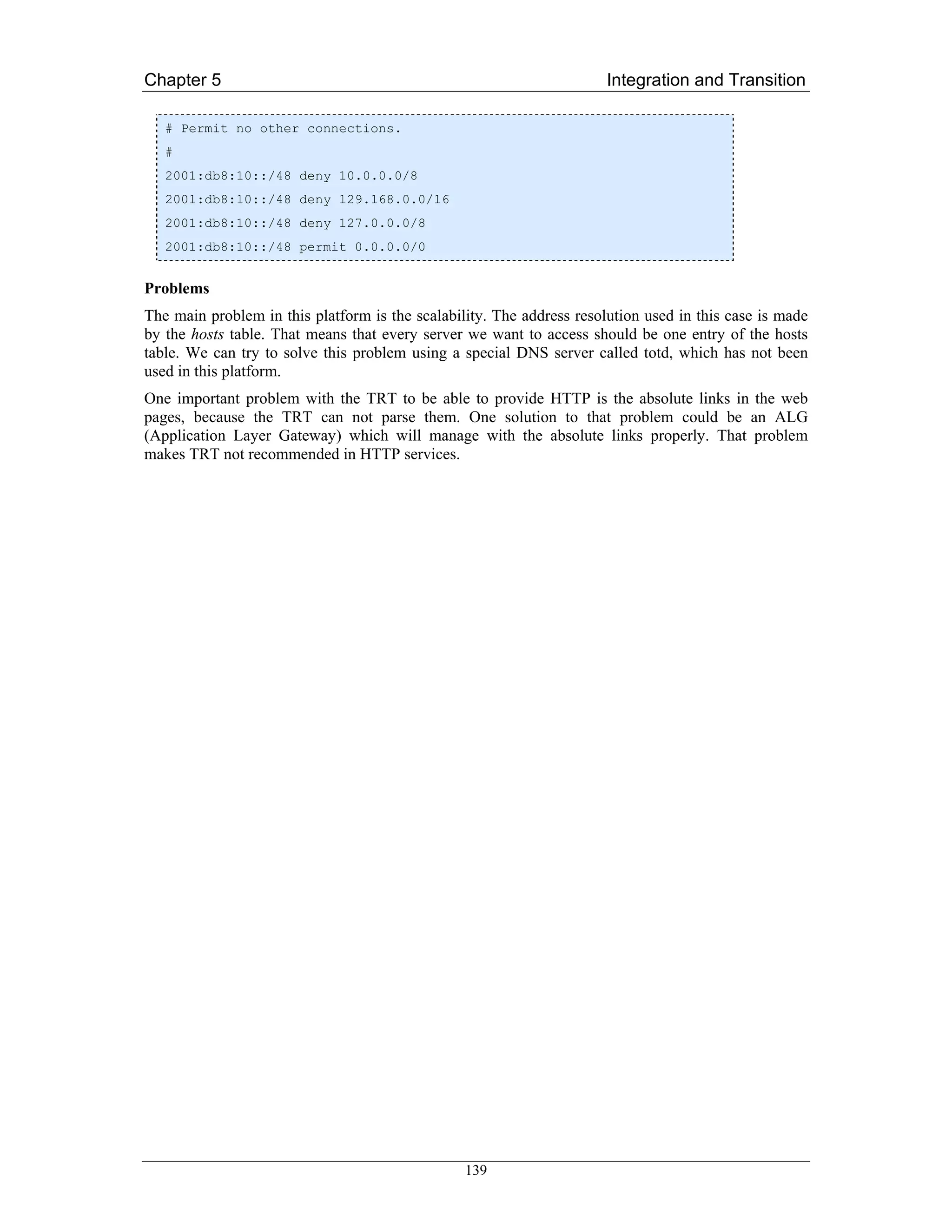
![Chapter 6 Routing
Figure 6-1 Classical IP Forwarding
Under the classical model of IP forwarding, every datagram generated by one of the end hosts (say, A
in Figure 6-1) travels through the sequence of routers almost unchanged. What changes from one hop
to the next one are the link layer headers that encapsulate the IP datagram. The link layer headers for
any two consecutive links can either be completely disparate (if the underlying link technologies are
not the same) or at least differ in link layer addressing information.
We said that the datagram is delivered by the IP network from one end host to the other one almost
unchanged. The routers along the forwarding path indeed do modify certain fields in the IP header but
such changes are minor and well defined – for example, the hop limit in the IPv6 header (or TTL in
IPv4) must be decremented at every hop. Specifically, the source and destination IP addresses in the
datagram header are not changed along the way and refer to the two end hosts.
As a matter of fact, the prevailing practice of the last decade or so made the above model of
transparent end-to-end communication rather rare. The current IPv4 Internet is full of various layer
violating devices (firewalls, NAT gateways, proxy servers etc.) and a vast majority of connected hosts
use private IPv4 addresses these days. Such an environment is hostile to certain classes of applications
(peer-to-peer, IP telephony etc.) and has also considerable drawbacks from the viewpoint of network
reliability and management. As discussed in [RFC2775], several factors are behind this significant
architectural shift. One of them has been the lack of global IPv4 addresses and this is where IPv6
could really help. However, layer violating devices are often deployed for other purposes, most
notably security, and so devices like firewalls are likely to persist in the IPv6 Internet as well (see
Chapter 9, Security).
6.1.2 Routing Tables
Routing decisions are based on data about reachability of various network prefixes that are either
manually configured or collected from routing protocols. This decision making is usually trivial for
end hosts (all traffic is sent to the default router) but becomes increasingly complicated as we move
towards the Internet core.
Reachability information concerning a specific network prefix is known as a route. Actual content of a
route depends both on the routing platform and the protocol that generated it, but typically we can
expect to find the following data:
1. Destination prefix consisting of a network address and prefix length.
141](https://image.slidesharecdn.com/ipv6deployment-guide-110112200202-phpapp01/75/IPv6-Deployment-Guide-155-2048.jpg)
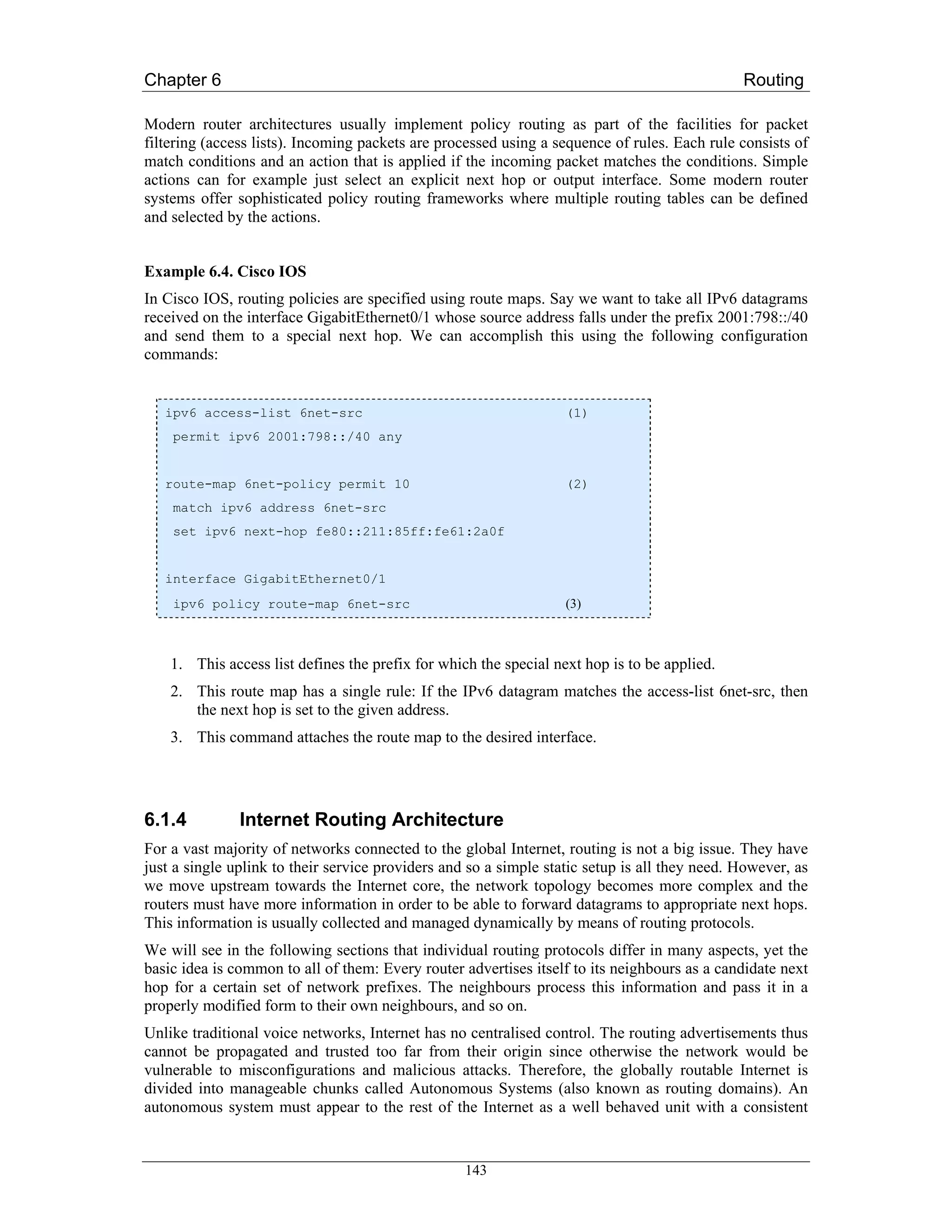
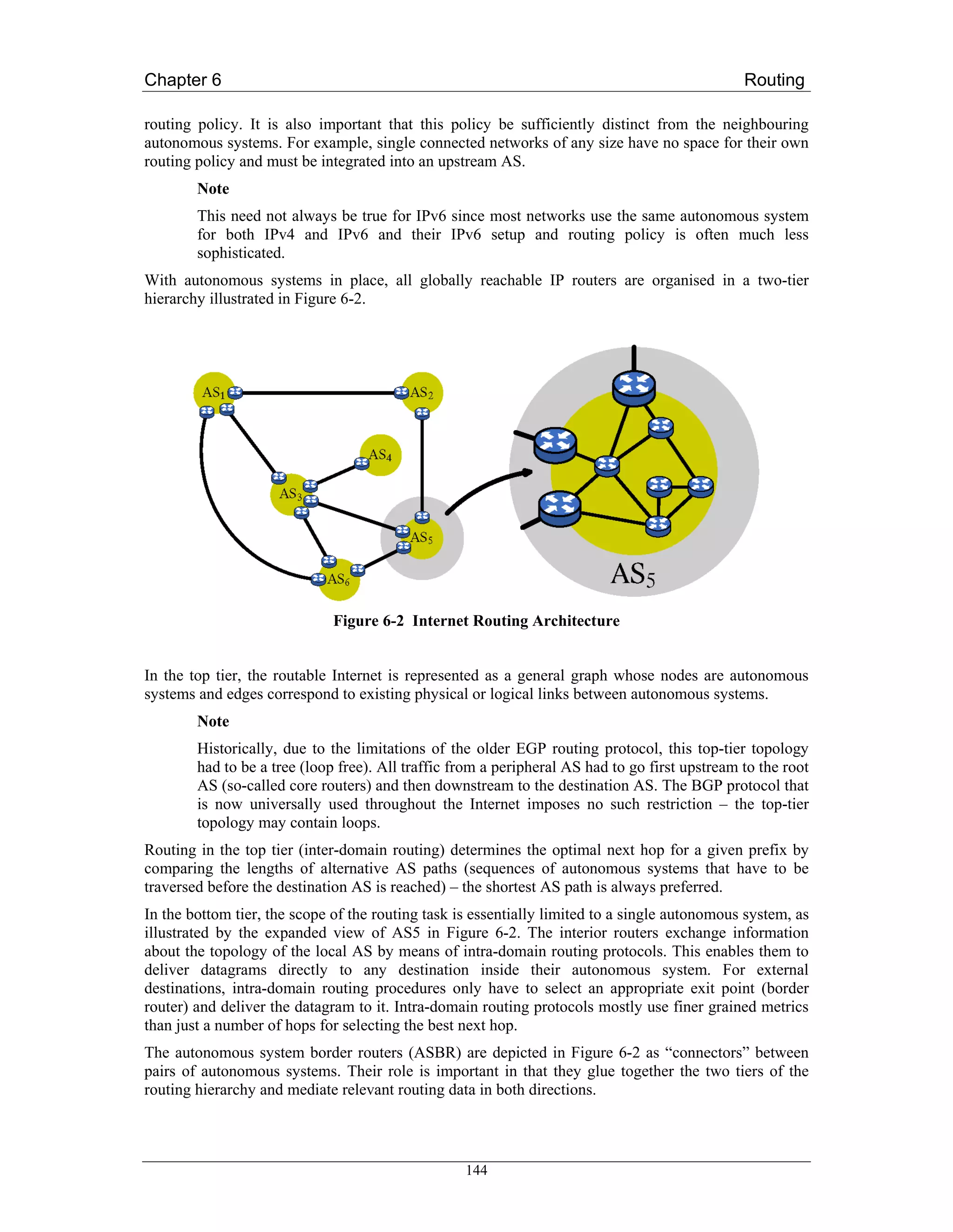
![Chapter 6 Routing
6.2 Implementing Static Routing for IPv6
6.2.1 Cisco IOS
6.2.1.1 Prerequisites
The minimum required IOS release for the static routing feature in each train is generally the one
where IPv6 became first available, that is 12.0(21)ST, 12.0(22)S, 12.2(2)T, 12.2(14)S, 12.3(2)T,
12.3(1)M.
Before configuring the router with a static IPv6 route you must enable the forwarding of IPv6 packets
using the ipv6 unicast-routing global configuration command. Then enable IPv6 on at least one
interface by configuring an IPv6 address on it, which can be accomplished with the command ipv6
address in the respective interface’s context.
6.2.1.2 Configuring Static Routes
Using static routes in IPv6 is similar to configuring static routes for IPv4 with a few differences. A
new command, ipv6 route, is used to configure IPv6 static routes and some of the IPv4 keywords are
not yet supported. The command structure is as follows:
Router(config)# ipv6 route ipv6-prefix/prefix-length
{ipv6-address | interface-type interface-number
[ipv6-address]} [administrative-distance]
Note that a floating static route must be configured with a greater administrative distance parameter
than any dynamic routing protocol because routes with smaller administrative distances are preferred.
By default, static routes have smaller administrative distances than dynamic routes.
Examples
a) In the following example the IPv6 default route is configured to point to serial interface 2/0:
Router(config) # ipv6 route ::/0 serial 2/0
b) This example shows a normal route configured to go through serial interface 0:
Router(config) # ipv6 route 2001:0db8::/32 serial 0
c) In this example an additional (optional) IPv6 address is configured for the next hop:
Router(config) # ipv6 route 2001:0db8::/32 ethernet 0 fe80::1
d) The following example shows how a static route can be configured with just the next hop IPv6
address omitting any interface specification:
Router(config) # ipv6 route 2001:0db8::/32 2002:806b:f0fe::1
146](https://image.slidesharecdn.com/ipv6deployment-guide-110112200202-phpapp01/75/IPv6-Deployment-Guide-160-2048.jpg)
![Chapter 6 Routing
6.2.1.3 Verifying Static IPv6 Route Configuration and Operation
To verify that static routes have been correctly configured one can use the show ipv6 route command,
which has the following syntax:
router # show ipv6 route [ipv6-address |
ipv6-prefix/prefix-length | protocol]
Examples
a) In the following example the show ipv6 route EXEC command is used to verify the
configuration of a static route through a point-to-point interface:
Router# show ipv6 route
IPv6 Routing Table - 9 entries
Codes: C - Connected, L - Local, S - Static, R - RIP, B - BGP
U - Per-user Static route
I1 - ISIS L1, I2 - ISIS L2, IA - ISIS interarea
O - OSPF intra, OI - OSPF inter, OE1 - OSPF ext 1, OE2 - OSPF ext 2
S 2001:0DB8::/32 [1/0]
via ::, Serial2/0
b) In this case, the show ipv6 route EXEC command is used to verify the configuration of a static
route on a multi-access interface. An IPv6 link-local address (FE80::1) is the next hop router.
Router# show ipv6 route
IPv6 Routing Table - 11 entries
Codes: C - Connected, L - Local, S - Static, R - RIP, B - BGP
U - Per-user Static route
I1 - ISIS L1, I2 - ISIS L2, IA - ISIS interarea
O - OSPF intra, OI - OSPF inter, OE1 - OSPF ext 1, OE2 - OSPF ext 2
S 2001:0DB8::/32 [1/0]
via FE80::1, Ethernet0/0
c) In this example, the show ipv6 route EXEC command is used with static as the value of the
protocol argument to display information about static routes installed in the IPv6 routing table:
Router# show ipv6 route static
IPv6 Routing Table - 330 entries
Codes: C - Connected, L - Local, S - Static, R - RIP, B - BGP
U - Per-user Static route
I1 - ISIS L1, I2 - ISIS L2, IA - ISIS interarea
S 2001:0DB8::/32 [1/0]
via ::, Tunnel0
S 2001:db8:C00:8011::/48 [1/0]
via ::, Null0
S ::/0 [254/0]
via 2002:806B:F0FE::1, Null
147](https://image.slidesharecdn.com/ipv6deployment-guide-110112200202-phpapp01/75/IPv6-Deployment-Guide-161-2048.jpg)
![Chapter 6 Routing
d) In the following example, the debug ipv6 routing privileged EXEC command is used to verify
the installation of a floating static route into the IPv6 routing table when an IPv6 RIP route is
deleted. The floating static IPv6 route was previously configured with an administrative
distance value of 130. The backup route was added as a floating static route because Routing
Information Protocol (RIP) routes have a default administrative distance of 120 and the RIP
route should be the preferred route. When the RIP route is deleted the floating static route is
installed in the IPv6 routing table.
Router# debug ipv6 routing
*Oct 10 18:28:00.847: IPv6RT0: rip two, Delete 2001:0DB8::/32 from table
*Oct 10 18:28:00.847: IPv6RT0: static, Backup call for 2001:0DB8::/32
*Oct 10 18:28:00.847: IPv6RT0: static, Add 2001:0DB8::/32 to table
*Oct 10 18:28:00.847: IPv6RT0: static, Adding next-hop :: over Serial2/0 for
2001:0DB8::/32, [130/0]
6.2.2 Juniper JunOS
The only difference in specifying static routes for IPv6 and IPv4 on Juniper platforms is that for the
new version of the Internet Protocol one needs to explicitly specify the IPv6 routing table (inet6.0,
inet6.2) in the statements. Other than that, syntax and options are very much the same and therefore
are not explained in this section.
6.2.2.1 Examples
a) Configure an IPv6 default route through the next-hop router 2001:638:500::1:
[edit]
user@host# set routing-options rib inet6.0 static
route abcd::/48 next-hop 2001:638:500::1
[edit]
user@host# show
routing-options {
static {
route abcd::/48 next-hop 2001:638:500::1;
}
}
b) Install an IPv6 static route into both inet6.0 and inet6.2 routing tables:
[edit routing-options rib table1.inet6.0 static]
rib-group groupA;
[edit routing-options rib-groups]
groupA {
148](https://image.slidesharecdn.com/ipv6deployment-guide-110112200202-phpapp01/75/IPv6-Deployment-Guide-162-2048.jpg)
![Chapter 6 Routing
import-rib [table1.inet6.0 inet6.0 inet6.2]
}
c) Propagate IPv6 static routes into the routing protocols:
[edit routing-options rib inet6.0 static (defaults | route)]
discard;
d) Resolve an IPv6 static route to non-next-hop router 2001:638:500:101::1/64 using next-hop
router 2001:638:500::1:
[edit]
user@host# set routing-options rib inet6.0 static route
2001:638:500:101::1/64 next-hop 2001:638:500::1 resolve
[edit]
user@host# show route 2001:638:500:101::/64
inet6.0: 26 destinations, 27 routes (25 active, 0 holddown, 1 hidden)
+ = Active Route, - = Last Active, * = Both
2001:638:500:101::/64 *[Static/5] 00:01:50
> to 2001:638:500::2 via ge-0/1/0.0
user@host# show route 2000::1
inet6.0: 26 destinations, 27 routes (25 active, 0 holddown, 1 hidden)
+ = Active Route, - = Last Active, * = Both
2000::/126 *[BGP/170] 00:05:32, MED 20, localpref 100
AS path: 2 I
> to 2001:638:500::2 via ge-0/1/0.0
6.2.3 Quagga/Zebra
Command Syntax:
Router(config)# ipv6 route <network> <gateway> [<distance>] {}
network is the destination prefix. gateway indicates the gateway for that prefix. As gateway you can
either specify an IPv6 address or interface name. If the interface name is null0 then Zebra installs a
blackhole route. distance is an optional parameter to install the route with a specified distance.
Command Syntax:
Router(config)# table <tableno> {}
149](https://image.slidesharecdn.com/ipv6deployment-guide-110112200202-phpapp01/75/IPv6-Deployment-Guide-163-2048.jpg)
![Chapter 6 Routing
Select the primary kernel routing table to be used. This only works for kernels supporting multiple
routing tables (like GNU/Linux 2.2.x and later). After setting tableno with this command, static
routes defined after this are added to the specified table.
Command Syntax:
Router# show ipv6 route [<route>]{}
This command can be used to display routes in the current selected routing table. To show a specific
route, specify it at the end.
150](https://image.slidesharecdn.com/ipv6deployment-guide-110112200202-phpapp01/75/IPv6-Deployment-Guide-164-2048.jpg)
![Chapter 6 Routing
6.3 RIP
RIP (Routing Information Protocol) is a true vintage class among the routing protocols that are still in
common use. Its ancestry goes back to the ARPANET routing algorithm that was designed in 1969
[MFR78]. In the mid-1970s, a similar protocol was implemented for the Xerox PARC Universal
Protocol (PUP) under the name Gateway Information Protocol (GWINFO). Later, GWINFO was
included in the Xerox Network System (XNS), but its name was changed to Routing Information
Protocol. However, the most important milestone in the RIP history was the release of the 4.2BSD
Unix in August 1983. This operating system included the routed daemon, essentially a generalisation
of the Xerox RIP capable of handling IP addresses and networks. The routed daemon then become a
de facto standard for intra-AS routing in the emerging Internet. It was not until 1988 that RIP became
a proposed standard in IETF [RFC1058].
The second version of RIP [RFC1723] added support for classless IPv4 addresses (CIDR) along with
other significant improvements. The strongest point of the RIP protocol is its simplicity, which makes
it easy to implement and configure. As a result, interoperable implementations have long been
available for virtually all IPv6 routing platforms and so RIPng used to be a popular choice, especially
in mixed environments. Although this niche is gradually being taken over by the more advanced intra-
AS routing protocols (IS-IS and OSPFv3), RIPng does still have some appeal, especially for small
networks.
On the other hand, the most serious weakness of RIP, and one that is unlikely to go away, is its hard
limit on path length: only 16! RIP considers destinations that are 16 or more hops away to be
unreachable. This may seem very restrictive but there are good reasons for keeping the maximum
allowable path length low.
6.3.1 RIPng Protocol
The IPv6 version of the RIP protocol (also known as RIPng) is defined in [RFC2080]. It is directly
based on the version 2 of RIP for IPv4 [RFC1723].
6.3.1.1 Protocol Data
Each router running the RIPng protocol keeps the information about all known networks in the
internal data structure called RIPng route table. It is essentially the RIPng-specific incarnation of the
distance vector with few additional items that are necessary for RIPng operation and cooperation with
other routing protocols. For every network, the routing table contains the following data:
• destination prefix
• metric
• next hop
• route tag
• route change flag
• route expiration timer
• garbage collection timer
The first three items together are known as a route and carry information about the reachability of a
network from the viewpoint of the particular router. The destination prefix consists of an IPv6 network
address and prefix length and identifies the network that the route table entry is about. The metric is
151](https://image.slidesharecdn.com/ipv6deployment-guide-110112200202-phpapp01/75/IPv6-Deployment-Guide-165-2048.jpg)
![Chapter 6 Routing
the distance to that network, or rather the current estimate of the distance. For directly connected
networks, the metric is set to the cost of that network. Finally, next hop contains the IP address of the
router that is next on the (provisional) optimum path to the destination network. For directly connected
networks, the next hop is irrelevant, usually empty.
The route tag is not of an immediate interest for RIPng; the standard only requires that the route tag be
preserved and redistributed with the route. It is typically used for tagging routes that were imported
from other routing protocols, for example BGP.
The route change flag and both timers are internal parameters that control the route processing. Their
role in RIPng operation will be explained in the next subsection.
The routers running RIPng exchange entire route tables or their portions between each other. Such an
exchange takes place in the following three cases:
1. About every 30 seconds, each router sends regular updates to all neighbours.
2. Whenever a router detects a change in network topology (e.g., a link going down), it sends to
all neighbours a triggered update containing only the routes that are affected by the topology
change.
3. Routers may also send their routing table or part of it after receiving an explicit Request
message from another router or host.
The routes are exchanged in the form of a data structure known as route table entry (RTE).
The current version of the RIPng protocol [RFC2080] defines two types of messages: Request and
Response. Both types have the same format as shown in Figure 6-3 and every message contains one or
more RTEs.
Figure 6-3 RIPng Message
6.3.1.2 Protocol Operation
If we start a packet sniffer on a network segment with active RIPng router, most of the time we will
only see the unsolicited Response messages similar to the one shown above. All routers send these
updates with a period of 30 seconds, but independently of each other, i.e., with random phase shifts.
Note
Actually, for networks with many RIPng routers it is quite important to keep the routers
unsynchronised, since otherwise a large number of Response messages sent within a short
interval may adversely influence the network performance. Interestingly enough, weakly
coupled periodic processes that are originally asynchronous often tend to synchronise. S.
Floyd and V. Jacobson [FJ94] showed this can also happen to a set of routers exchanging
152](https://image.slidesharecdn.com/ipv6deployment-guide-110112200202-phpapp01/75/IPv6-Deployment-Guide-166-2048.jpg)
![Chapter 6 Routing
periodic messages. To counter this phenomenon, the RIPng specifications requires the
implementations either to derive the period of the messages from a precise clock that is not
influenced by system load, or each time add a random offset to the nominal 30-second period
so that the period is uniformly distributed between 15 and 45 seconds.
The essential part of the RIPng router operation involves the following two procedures:
1. Listen to the route advertisements sent by its neighbours and update its own routing table so
that it contains the best routes (with shortest metrics) heard so far.
2. Every 30 seconds, send the current route table to all neighbours.
6.4 Implementing RIPng for IPv6
IPv6 RIP or RIPng (RIP Next Generation) is generally very similar to RIP (for IPv4) and functions in
the same way, offering the same benefits. RIP enhancements for IPv6 (RIPng) is detailed in RFC 2080
[RFC2080] and includes support for IPv6 addresses and prefixes, and the use of all-RIP-routers
multicast group address FF02::9 as the destination address for RIP update messages.
The RIPng IGP uses the Bellman-Ford distance-vector algorithm to determine the best route to a
destination. RIPng uses the hop count as the metric and allows hosts and routers to exchange
information for computing routes through an IP-based network. RIPng is intended to act as an IGP for
moderately sized autonomous systems (ASs).
RIPng is a User Datagram Protocol (UDP)-based protocol and uses UDP port 521.
RIPng has the following architectural limitations:
• The longest network path cannot exceed 15 hops (assuming that each network, or hop, has a
cost of 1).
• RIPng depends on counting to infinity to resolve certain unusual situations. When the network
consists of several hundred routers, and when a routing loop has formed, the amount of time
and network bandwidth required to resolve a next hop might be great.
• RIPng uses only a fixed metric to select a route. Other IGPs use additional parameters, such as
measured delay, reliability and load.
A RIPng packet header contains the following fields:
• Command—Indicates whether the packet is a request or response message. Request messages
seeks information for the router’s routing table. Response messages are sent periodically or
when a request message is received. Periodic response messages are called update messages.
Update messages contain the command and version fields and a set of destinations and
metrics.
• Version number—Specifies the version of RIPng that the originating router is running. This is
currently set to Version 1.
The rest of the RIPng packet contains a list of routing table entries with the following fields:
• Destination prefix—128-bit IPv6 address prefix for the destination.
• Prefix length—Number of significant bits in the prefix.
• Metric—Value of the metric advertised for the address.
153](https://image.slidesharecdn.com/ipv6deployment-guide-110112200202-phpapp01/75/IPv6-Deployment-Guide-167-2048.jpg)
![Chapter 6 Routing
6.4.1.4 IPv6 prefix lists to filter routes on outgoing or incoming RIP updates
IPv6 prefix lists are used to specify certain prefixes or a range of prefixes that must be matched before
a permit or deny statement can be applied. Two operand keywords can be used to designate a range of
prefix lengths to be matched. A prefix length of less than, or equal to, a value is configured with the le
keyword. A prefix length greater than, or equal to, a value is specified using the ge keyword. The ge
and le keywords can be used to specify the range of the prefix length to be matched in more detail
than the usual ipv6-prefix/prefix-length argument. For a candidate prefix to match against a
prefix list entry three conditions can exist:
• the candidate prefix must match the specified prefix list and prefix length entry;
• the value of the optional le keyword specifies the range of allowed prefix lengths from the
prefix-length argument up to, and including, the value of the le keyword;
• the value of the optional ge keyword specifies the range of allowed prefix lengths from the
value of the ge keyword up to, and including, 128.
Note: The first condition must match before the other conditions take effect.
An exact match is assumed when the ge or le keywords are not specified. If only one keyword
operand is specified then the condition for that keyword is applied, and the other condition is not
applied. The prefix-length value must be less than the ge value. The ge value must be less than, or
equal to, the le value. The le value must be less than or equal to 128.
An IPv6 prefix list is created by specifying its first entry in the global configuration environment. The
command syntax to either deny specific routes or permit them is as follows:
Command syntax:
Router(config)# ipv6 prefix-list prefix-list-name
[seq seq-number] {deny ipv6-prefix/prefix-length
| description text} [ge ge-value] [le le-value]
Router(config)# ipv6 prefix-list prefix-list-name
[seq seq-number] {permit ipv6-prefix/prefix-length
| description text} [ge ge-value] [le le-value]
The optional seq parameter specifies the sequence number of the corresponding entry in the specified
prefix-list.
To enter more than one filter to any prefix list repeat the above commands specifying the same
prefix-list-name as often as needed with the appropriate parameters.
IPv6 prefix lists can be applied to specific IPv6 RIP routing updates that are received or sent on the
specific interface with the following command:
Command syntax:
Router(config-router)# distribute-list prefix-list
prefix-list-name {in | out} [interface-type interface-number]
Note: If an interface is not specified with the distribute-list prefix-list command, the specified prefix
list is applied to IPv6 routing updates that are sent or received on all interfaces in the router running
the specified process.
The in keyword applies the prefix list to incoming routing updates on the specified interface.
The out keyword applies the prefix list to outgoing routing updates on the specified interface.
156](https://image.slidesharecdn.com/ipv6deployment-guide-110112200202-phpapp01/75/IPv6-Deployment-Guide-170-2048.jpg)
![Chapter 6 Routing
Examples
a) In this example, the default IPv6 route will be denied.
Router(config)# ipv6 prefix-list eth0/0-in-flt seq 10 deny ::/0
b) In this example, all routes are permitted. This entry is following the deny rule in Step a) in
order to permit all other routes, except the IPv6 default route. Without this permit rule all
prefixes would be blocked.
Router(config)# ipv6 prefix-list eth0/0-in-flt seq 20 permit ::/0 le 128
c) In the following example, the ipv6 prefix-list “eth0/0-in-flt” is distributed to IPv6 RIP routing
process “ciscotest”. It is specifically used to filter routes coming in through interface Ethernet
0/0. The result is that all routes but the IPv6 default route are accepted.
Router(config)# ipv6 router rip ciscotest
Router(config-router)# distribute-list prefix-list eth0/0-in-flt
in Ethernet 0/0
6.4.1.5 Route Tags and Redistribution of Routes into an RIP Routing Process
This task explains how to set route tags using a route map and redistribute tagged routes into an IPv6
RIP routing process.
Defining route maps and tagging routes for IPv6 is not much different from the same task in IPv4. The
only difference is the fact that route maps match to IPv6 prefix lists.
Command syntax:
Router(config)# route-map map-tag [permit | deny] [sequence-number]
Router(config-route-map)# match ipv6 address prefix-list prefix-list-name
Router(config-route-map)# set tag value
Note: IPv6 RIP does not support route tags when the number of parallel routes is configured to be
greater than one. Use the maximum-paths command to configure the number of parallel routes.
Redistribution of routes defined in a route map is then set in the respective IPv6 RIP process with the
redistribute command:
Router(config-router)# redistribute protocol [process-id]
{level-1 | level-1-2 | level-2} [metric metric-value]
[metric-type {internal | external}] [route-map map-name]
The protocol argument can be one of the following keywords: bgp, connected, isis, rip, or
static.
The rip keyword and process-id argument specify an IPv6 RIP routing process.
Note: The connected keyword refers to routes that are established automatically by assigning IPv6
addresses to an interface.
157](https://image.slidesharecdn.com/ipv6deployment-guide-110112200202-phpapp01/75/IPv6-Deployment-Guide-171-2048.jpg)
![Chapter 6 Routing
Examples
This example shows how a route map with the name bgp-to-rip is defined to match a previously
defined IPv6 prefix list with the name bgp-to-rip-flt. This route map is then used to tag those
routes with the tag “4” and to subsequently be used to redistribute them in an RIP routing process:
Router(config) # route-map bgp-to-rip permit 10
Router(config-route-map)# match ipv6 address prefix-list bgp-to-rip-flt
Router(config-route-map)# set tag 4
Router(config-route-map)# exit
Router(config)# ipv6 router rip ciscotest
Router(config-router)# redistribute bgp 65001 route-map bgp-to-rip
6.4.1.6 Verifying IPv6 RIP Configuration and Operation
This task explains how to display information to verify the configuration and operation of IPv6 RIP.
The commands, which are specific to RIP in this context are show ipv6 rip and debug ipv6 rip, but as
with static routes show ipv6 route is also useful in this task. To display information about current IPv6
RIP processes use the following command:
Router> show ipv6 rip [name] [database | next-hops]
Note that this command may be used as an unprivileged user.
Debugging messages to IPv6 RIP routing transactions may be displayed with the following command
syntax:
Router# debug ipv6 rip [interface-type interface-number]
The debugging information may be constrained to just those transactions taking place on a specific
interface. The command may only be executed by privileged users.
For the syntax of the show ipv6 route command please refer to section 6.2.1.
Examples
a) In the following example, output information about all current IPv6 RIP processes is displayed
using the show ipv6 rip user EXEC command:
Router> show ipv6 rip
RIP process “cisco”, port 521, multicast-group FF02::9, pid 62
Administrative distance is 120. Maximum paths is 1
Updates every 5 seconds, expire after 15
Holddown lasts 10 seconds, garbage collect after 30
Split horizon is on; poison reverse is off
Default routes are generated
Periodic updates 223, trigger updates 1
Interfaces:
Ethernet0/0
Redistribution:
Redistributing protocol bgp 65001 route-map bgp-to-rip
158](https://image.slidesharecdn.com/ipv6deployment-guide-110112200202-phpapp01/75/IPv6-Deployment-Guide-172-2048.jpg)
![Chapter 6 Routing
b) In the following example, output information about a specified IPv6 RIP process database is
displayed using the show ipv6 rip user EXEC command with the name argument and the
database keyword. In the following output for the IPv6 RIP process named ciscotest, timer
information is displayed, and route 4002::16/64 has a route tag set:
Router> show ipv6 rip ciscotest database
RIP process “ciscotest”, local RIB
2000::/64, metric 2
Ethernet0/0/FE80::A8BB:CCFF:FE00:B00, expires in 13 secs
4000::/16, metric 2 tag 4, installed
Ethernet0/0/FE80::A8BB:CCFF:FE00:B00, expires in 13 secs
4001::/16, metric 2 tag 4, installed
Ethernet0/0/FE80::A8BB:CCFF:FE00:B00, expires in 13 secs
4002::/16, metric 2 tag 4, installed
Ethernet0/0/FE80::A8BB:CCFF:FE00:B00, expires in 13 secs
::/0, metric 2, installed
Ethernet0/0/FE80::A8BB:CCFF:FE00:B00, expires in 13 secs
c) In the following example, output information for a specified IPv6 RIP process is displayed
using the show ipv6 rip user EXEC command with the name argument and the next-hops
keyword:
Router> show ipv6 rip ciscotest next-hops
RIP process “ciscotest”, Next Hops
FE80::A8BB:CCFF:FE00:A00/Ethernet0/0 [4 paths]
d) In the following example, output information for all IPv6 RIP routes is displayed using the
show ipv6 route user EXEC command with the rip protocol keyword:
Router> show ipv6 route rip
IPv6 Routing Table - 17 entries
Codes: C - Connected, L - Local, S - Static, R - RIP, B - BGP
U - Per-user Static route
I1 - ISIS L1, I2 - ISIS L2, IA - ISIS interarea
O - OSPF intra, OI - OSPF inter, OE1 - OSPF ext 1, OE2 - OSPF ext 2
R 2001:1::/32 [120/2]
via FE80::A8BB:CCFF:FE00:A00, Ethernet0/0
R 2001:2::/32 [120/2]
via FE80::A8BB:CCFF:FE00:A00, Ethernet0/0
R 2001:3::/32 [120/2]
via FE80::A8BB:CCFF:FE00:A00, Ethernet0/0
e) In the following example, debugging messages for IPv6 RIP routing transactions are displayed
using the debug ipv6 rip privileged EXEC command:
159](https://image.slidesharecdn.com/ipv6deployment-guide-110112200202-phpapp01/75/IPv6-Deployment-Guide-173-2048.jpg)
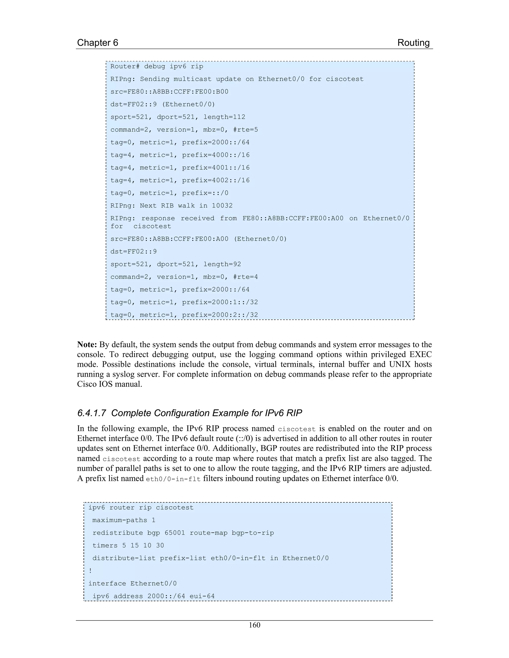
![Chapter 6 Routing
ipv6 rip ciscotest enable
ipv6 rip ciscotest default-information originate
!
ipv6 prefix-list bgp-to-rip-flt seq 10 deny 4003::/16 le 128
ipv6 prefix-list bgp-to-rip-flt seq 20 permit 4000::/8 le 128
!
ipv6 prefix-list eth0/0-in-flt seq 10 deny ::/0
ipv6 prefix-list eth0/0-in-flt seq 15 permit ::/0 le 128
!
route-map bgp-to-rip permit 10
match ipv6 address prefix-list bgp-to-rip-flt
set tag 4
6.4.2 Juniper JunOS
The JUNOS software implementation of RIPng is similar to RIPv2. However, RIPng is a distinct
routing protocol from RIPv2 and differs in a few aspects from the older version of RIP. Aside from the
general architectural limitations of RIPng as stated at the beginning of this chapter the following
additional differences are specific to JunOS in comparison to RIPv2:
RIPng does not need to implement authentication on packets.
• There is no support for multiple instances of RIPng.
• There is no support for RIPng routing table groups.
6.4.2.1 Configuring RIPng
To configure Routing Information Protocol Next-Generation (RIPng), you include the following
statements:
protocols {
ripng {
graceful-restart {
disable;
restart-time seconds;
}
holddown seconds;
import [ policy-names ];
metric-in metric;
receive <none>;
send <none>;
traceoptions {
file name <replace> <size size> <files number> <no-stamp>
<(world-readable | no-world-readable)>;
161](https://image.slidesharecdn.com/ipv6deployment-guide-110112200202-phpapp01/75/IPv6-Deployment-Guide-175-2048.jpg)
![Chapter 6 Routing
flag flag <flag-modifier> <disable>;
}
group group-name {
export [ policy-names ];
metric-out metric;
preference number;
neighbor neighbor-name {
import [ policy-names ];
metric-in metric;
receive <none>;
send <none>;
}
}
}
}
6.4.2.2 Define RIPng Global Properties
When RIPng detects a route with a high metric associated, the router waits for a period of time before
making any updates into the routing table. This minimises the effects of route flapping to the routing
table. The period of time that RIPng waits is the hold-down timer.
To configure the hold-down timer for RIPng, include the holddown statement, which can be a value
from 10 through 180. The default value is 180 seconds.
Graceful restart is disabled by default. You can globally enable graceful restart for all routing
protocols under the [edit routing-options] hierarchy level.
You can configure graceful restart parameters specifically for RIPng. To do this, include the
graceful-restart statement.
To disable graceful restart for RIPng, specify the disable statement. To configure a time period for
the restart to finish, specify the restart-time statement.
6.4.2.3 Define RIPng Global and Neighbour-Specific Properties
To define RIPng properties can be entered either in the global RIPng configuration context and/or with
each neighbour. They either apply to all or just to a specific RIPng neighbour.
[edit protocols ripng ]
import [ policy-names ];
metric-in metric ;
receive receive-options ;
send send-options ;
[edit protocols ripng group group-name]
neighbor neighbor-name {
162](https://image.slidesharecdn.com/ipv6deployment-guide-110112200202-phpapp01/75/IPv6-Deployment-Guide-176-2048.jpg)
![Chapter 6 Routing
import [ policy-names ];
metric-in metric;
receive receive-options;
send send-options;
}
By default, RIPng imports routes from the neighbours configured with the neighbor statement. These
routes include those learned from RIPng as well as those learned from other protocols. By default,
routes that RIPng imports from its neighbors have a metric of 1 added to the current route metric.
To change the default metric to be added to incoming routes, include the metric-in statement, which
can be a value from 1 through 15. A value of 16 indicates infinity or unreachable.
You can enable and disable the sending or receiving of update messages. By default, sending and
receiving update messages is enabled. To disable the sending and receiving of update messages,
include the receive and send statements with the none keyword
To enable the sending and receiving of update messages, just include the receive and send
statements.
To filter routes being imported by the local router from its neighbours, include the import statement
and list the names of one or more policies to be evaluated. If you specify more than one policy, they
are evaluated in order (first to last) and the first matching policy is applied to the route. If no match is
found, the local router does not import any routes.
6.4.2.4 Defining RIPng Neighbour-Specific Properties
By default, RIPng does not export routes it has learned to its neighbours. To have RIPng export routes,
apply one or more export policies. To apply export policies and to filter routes being exported from the
local router to its neighbors, include the export statement and list the name of the policy to be
evaluated.
You can define one or more export policies. If no routes match the policies, the local router does not
export any routes to its neighbors. Export policies override any metric values determined through
calculations involving the metric-in (see above) and metric-out values.
If you configure an export policy, RIPng exports routes it has learned to the neighbours configured
with the neighbor statement.
If a route being exported was learned from a member of the same RIPng group, the metric associated
with that route (unless modified by an export policy) is the normal RIPng metric. For example, a
RIPng route with a metric of 5 learned from a neighbor configured with a metric-in value of 2 is
advertised with a combined metric of 7 when advertised to RIPng neighbors in the same group.
However, if this route was learned from a RIPng neighbor in a different group or from a different
protocol, the route is advertised with the metric value configured for that group with the metric-out
statement. The default value for metric-out is 1.
By default, the JunOS software assigns a preference of 100 to routes that originate from RIPng. When
the JunOS software determines a route’s preference to become the active route, the software selects
the route with the lowest preference and installs this route into the forwarding table.
To modify the default RIPng preference value, include the preference statement, which can be a
value from 0 through 4,294,967,295 (232 - 1).
163](https://image.slidesharecdn.com/ipv6deployment-guide-110112200202-phpapp01/75/IPv6-Deployment-Guide-177-2048.jpg)
![Chapter 6 Routing
6.4.2.5 Tracing RIPng traffic
To trace RIPng protocol traffic, you can specify options in the global traceoptions statement at the
[edit routing-options] hierarchy level, and specify RIPng-specific options by including the
traceoptions statement:
You can specify the following RIPng-specific options in the RIPng traceoptions statement:
• all - Trace everything.
• error - Trace RIPng errors.
• expiration - Trace RIPng route expiration processing.
• general - Trace general events.
• holddown - Trace RIPng hold-down processing.
• normal - Trace normal events.
• packets - Trace all RIPng packets.
• policy - Trace policy processing.
• request - Trace RIPng information packets.
• route - Trace routing information.
• state - Trace state transitions.
• task - Trace routing protocol task processing.
• timer - Trace routing protocol timer processing.
• trigger - Trace RIPng triggered updates.
• update - Trace RIPng update packets.
Note: Use the traceoption flags detail and all with caution. These flags may cause the CPU to
become very busy.
6.4.2.6 Complete Configuration Example
Configure RIPng:
[edit policy-options]
policy-statement redist-direct {
from protocol direct;
then accept;
}
[edit protocols ripng]
metric-in 3;
group wan {
metric-out 2;
export redist-direct;
164](https://image.slidesharecdn.com/ipv6deployment-guide-110112200202-phpapp01/75/IPv6-Deployment-Guide-178-2048.jpg)
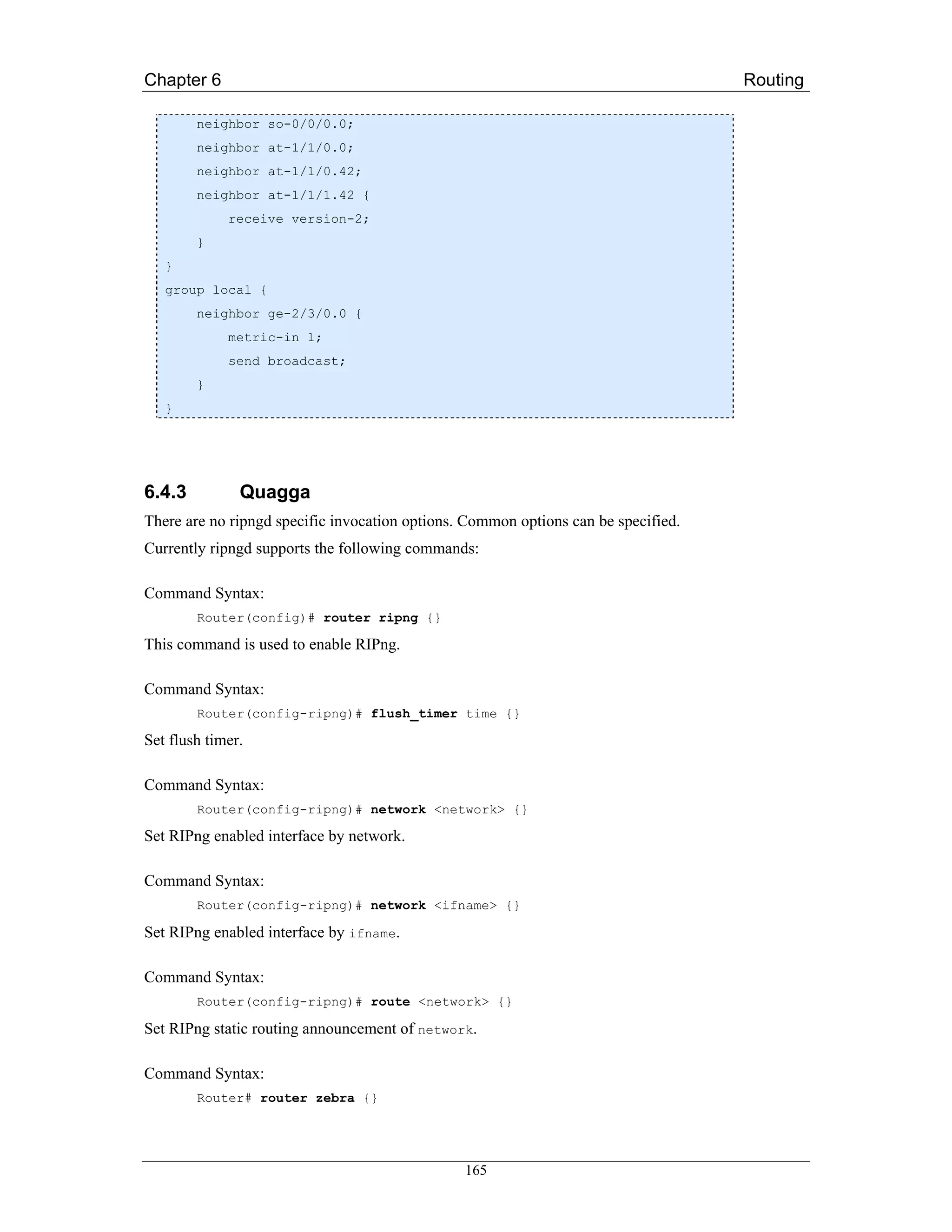
![Chapter 6 Routing
operating in multi topology IPv6 mode, the topological restrictions of single topology mode are no
longer in effect.
6.5.1.2 Prerequisites
For the minimum required IOS version for IS-IS features please refer to:
http://www.cisco.com/univercd/cc/td/doc/product/software/ios123/123cgcr/ipv6_c/ftipv6s.htm#wp10 04964
Before configuring the router to run IPv6 IS-IS, globally enable IPv6 using the ipv6 unicast-routing
global configuration command.
6.5.1.3 Restrictions for Implementing IS-IS for IPv6
In Cisco IOS Release 12.0(21)ST, Cisco IOS Release 12.0(22)S or later releases, and Cisco IOS
Release 12.2(8)T or later releases, IS-IS support for IPv6 implements single topology IPv6 IS-IS
functionality based on IETF IS-IS working group draft draft-ietf-isis-ipv6 [Hop03]. A single shortest
path first (SPF) per level is used to compute OSI, IPv4 (if configured) and IPv6 routes. The use of a
single SPF means that both IPv4 IS-IS and IPv6 IS-IS routing protocols must share a common network
topology. To use IS-IS for IPv4 and IPv6 routing, any interface configured for IPv4 IS-IS must also be
configured for IPv6 IS-IS, and vice versa. All routers within an IS-IS area (Level 1 routing) or domain
(Level 2 routing) must also support the same set of address families: IPv4 only, IPv6 only, or both
IPv4 and IPv6.
Beginning with release Cisco IOS Release 12.2(15)T, Cisco IOS Release 12.2(18)S and Cisco IOS
Release 12.3(1)M, IS-IS support for IPv6 is enhanced to also support multitopology IPv6 support as
defined in IETF IS-IS WG draft-ietf-isis-wg-multi-topology.txt [PSS05]. Multitopology IPv6 IS-IS
support uses multiple SPFs to compute routes and removes the restriction that all interfaces must
support all configured address families and that all routers in an IS-IS area or domain must support the
same set of address families.
The following IS-IS router configuration commands are specific to IPv4 and are not supported by, or
have any effect on, IPv6 IS-IS:
mpls
traffic-share
If you are using IS-IS single topology support for IPv6, IPv4, or both IPv6 and IPv4, you may
configure both IPv6 and IPv4 on an IS-IS interface for Level 1, Level 2, or both Level 1 and Level 2.
However, if both IPv6 and IPv4 are configured on the same interface, they must be running the same
IS-IS level. That is, IPv4 cannot be configured to run on IS-IS Level 1 only on a specified Ethernet
interface while IPv6 is configured to run IS-IS Level 2 only on the same Ethernet interface.
6.5.1.4 Configuring Single Topology IS-IS for IPv6
This task explains how to create an IPv6 IS-IS process and enable IPv6 IS-IS support on an interface.
Configuring IS-IS comprises two activities. The first activity, creates an IS-IS routing process using
protocol-independent IS-IS commands. The second activity, configures the operation of the IS-IS
protocol on an interface.
Command syntax for the global protocol-independent configuration:
To enable IS-IS for the specified IS-IS routing process, and enter router configuration mode use the
following command:
Router(config)# router isis area-name
168](https://image.slidesharecdn.com/ipv6deployment-guide-110112200202-phpapp01/75/IPv6-Deployment-Guide-182-2048.jpg)
![Chapter 6 Routing
Next, configure an IS-IS network entity title (net) for the routing process:
Router(config-router)# net network-entity-title
The network-entity-title argument defines the area addresses for the IS-IS area and the system ID
of the router.
After configuring an IS-IS routing process it may be enabled on appropriate interfaces by the
following command:
Router(config-if)# ipv6 router isis area-name
Examples
The following example shows the minimal configuration necessary to enable single topology IS-IS for
IPv6 on a router. First the routing process is created, then this process is enabled on Ethernet interface
0/0/1.
Router(config)# router isis area2
Router(config-router)# net 49.0001.0000.0000.000c.00
Router(config-router)# exit
Router(config)# interface Ethernet 0/0/1
Router(config-if)# ipv6 address 2001:0DB8::3/64
Router(config-if)# ipv6 router isis area2
Router(config-if)# exit
Router(config)#
6.5.1.5 Configuring Multi Topology IS-IS for IPv6
This task explains how to configure multi topology IS-IS in IPv6. For these optional configuration
steps it is assumed that IS-IS for IPv6 is already configured as described in the previous section. The
commands described below may then be entered in the configuration context of the corresponding IS-
IS routing process.
When multi topology IS-IS for IPv6 is configured, the transition keyword allows a user who is
working with the single topology SPF mode of IS-IS IPv6 to continue to work while upgrading to
multi topology IS-IS. After every router is configured with the transition keyword, users can remove
the transition keyword on each router. When transition mode is not enabled, IPv6 connectivity
between routers operating in single topology mode and routers operating in multi topology mode is not
possible.
You can continue to use the existing IPv6 topology while upgrading to multi topology IS-IS. The
optional isis ipv6 metric command allows you to differentiate between link costs for IPv6 and
IPv4 traffic when operating in multi topology mode.
Command syntax to enable multi topology IS-IS:
The following command configures a router running IS-IS to generate and accept only new style
TLVs:
Router(config-router)# metric-style wide [transition]
[level-1 | level-2 | level-1-2]
Now, one enters IPv6 address family configuration mode.
Router(config-router)# address-family ipv6 [unicast]
169](https://image.slidesharecdn.com/ipv6deployment-guide-110112200202-phpapp01/75/IPv6-Deployment-Guide-183-2048.jpg)
![Chapter 6 Routing
The unicast keyword specifies the IPv6 unicast address family which is the default in this case
anyway.
Within the IPv6 address family multi topology IS-IS for IPv6 can be enabled with the following
command:
Router(config-router-af)# multi-topology [transition]
The optional transition keyword allows an IS-IS IPv6 user to continue to use single topology mode
while upgrading to multi topology mode (s.a.).
Examples
In the following example a previously configured (single topology) IS-IS session “area2” is switched
to multi topology IS-IS.
Router(config)# router isis area2
Router(config-router)# metric-style wide level-1
Router(config-router)# address-family ipv6
Router(config-router-af)# multi-topology
Router(config-router-af)# exit
Router(config-router)# exit
Router(config)#
6.5.1.6 Customizing IPv6 IS-IS
This task explains how to configure a new administrative distance for IPv6 IS-IS, configure the
maximum number of equal-cost paths that IPv6 IS-IS will support, configure summary prefixes for
IPv6 IS-IS, and configure an IS-IS instance to advertise the default IPv6 route (::/0). It also explains
how to configure the hold down period between partial route calculations (PRCs) and how often Cisco
IOS software performs the SPF calculation when using multitopology IS-IS.
You can customize IS-IS multitopology for IPv6 for your network, but you likely will not need to do
so. The defaults for this feature are set to meet the requirements of most customers and features. If you
change the defaults, refer to Cisco IPv4 configuration guide and IPv6 command reference to find the
appropriate syntax.
Command syntax for customization of single topology IS-IS for IPv6:
To inject the default route into an IS-IS routing domain the following command may be entered in the
address family ipv6 context of the corresponding IS-IS process:
Router(config-router-af)# default-information originate [route-map map-name]
The route-map keyword and map-name argument specify the conditions under which the IPv6 default
route is advertised.
If the route-map keyword is omitted, then the IPv6 default route will be unconditionally advertised at
Level 2.
The following command defines an administrative distance for IPv6 IS-IS routes in the IPv6 routing
table. Like the previous command it is entered in the address family ipv6 context.
Router(config-router-af)# distance value
The value argument is an integer from 10 to 254 (values 0 to 9 are reserved for internal use).
170](https://image.slidesharecdn.com/ipv6deployment-guide-110112200202-phpapp01/75/IPv6-Deployment-Guide-184-2048.jpg)
![Chapter 6 Routing
As with RIP and BGP one may define the maximum number of equal-cost routes that IPv6 IS-IS can
support:
Router(config-router-af)# maximum-paths number-paths
Optionally one can allow a Level 1-2 router to summarize Level 1 prefixes at Level 2, instead of
advertising the Level 1 prefixes directly when the router advertises the summary.
Router(config-router-af)# summary-prefix ipv6-prefix/prefix-length
[level-1 | level-1-2 | level-2]
The ipv6-prefix argument in the summary-prefix command must be in the form documented in RFC
2373 [RFC2373] where the address is specified in hexadecimal using 16-bit values between colons.
The argument is a decimal value that indicates how many high-order contiguous bits of the address
comprise the prefix (the network portion of the address). A slash mark must precede the decimal
value.
Last but not least, the hold down period between PRCs and the interval between SPF calculations for
multitopology IS-IS may also be manually set within the address family ipv6 context:
Router(config-router-af)# prc-interval seconds
[initial-wait] [secondary-wait]
Router(config-router-af)# spf-interval [level-1 | level-2]
seconds [initial-wait] [secondary-wait]
The value of a multitopology IS-IS metric is not global but specific to an interface. Therefore it must
be entered in that interface’s configuration context:
Router(config-if) # isis ipv6 metric metric-value
[level-1 | level-2 | level-1-2]
Examples
a) In the following example the IPv6 default route will be unconditionally advertised at Level 2:
Router(config)# router isis area2
Router(config-router)# address-family ipv6
Router(config-router-af)# default-information originate
b) This example shows the administrative distance of IPv6 IS-IS routes in this domain set to
“90”:
Router(config-router-af)# distance 90
c) In the following example all Level 1 routes belonging to the specified prefix are summarized
at level 2:
Router(config-router-af)# summary-prefix 2001:0DB8::/24
d) This example shows the manual setting of IS-IS timers for IPv6:
Router(config-router-af)# prc-interval 20
Router(config-router-af)# spf-interval 30
171](https://image.slidesharecdn.com/ipv6deployment-guide-110112200202-phpapp01/75/IPv6-Deployment-Guide-185-2048.jpg)
![Chapter 6 Routing
e) For the last configuration example the routing context is exited and the configuration context
for Ethernet interface 0/0/1 is entered to configure the metric for a multitopology IS-IS
process on the routes from this interface:
Router(config-router-af)# exit
Router(config-router)# exit
Router(config)# interface Ethernet 0/0/1
Router(config-if)# isis ipv6 metric 20
6.5.1.7 Redistributing Routes
IPv6 Routes from another routing process/protocol can also be redistributed to an IPv6 IS-IS routing
process. The corresponding redistribute command is entered in the address family ipv6 context of
the IS-IS routing process:
Router(config-router-af)# redistribute protocol [process-id]
[level-1 | level-1-2 | level-2] [metric metric-value]
[metric-type {internal | external}] [route-map map-name]
The protocol argument can be one of the following keywords: bgp, connected, isis, rip or static.
IPv6 routes learned on one IS-IS level may also be redistributed to another level of the same process.
The corresponding redistribute command in this case includes the keyword into:
Router(config-router-af)# redistribute protocol
[level-1 [into level-2] | level-1-2 | level-2
[into level-1]]
By default, routes learned by Level 1 instances are redistributed by Level 2 instance.
Note: The protocol argument must be isis in this configuration of the redistribute command.
Examples
a) In the following example bgp routes from bgp process 64500 are redistributed into the IS-IS
routing domain with metric value:
Router(config-router-af)# redistribute bgp 64500
metric 100 route-map isismap
b) This example shows how IS-IS Level 1 routes are distributed in Level 2 domain:
Router(config-router-af)# redistribute isis level-1 into level-2
6.5.1.8 Disabling Consistency Checks
For single topology IS-IS IPv6, routers must be configured to run the same set of address families. IS-
IS performs consistency checks on hello packets and will reject hello packets that do not have the
same set of configured address families. For example, a router running IS-IS for both IPv4 and IPv6
will not form an adjacency with a router running IS-IS for IPv4 or IPv6 only. In order to allow
adjacency to be formed in mismatched address families network, the adjacency-check command in
172](https://image.slidesharecdn.com/ipv6deployment-guide-110112200202-phpapp01/75/IPv6-Deployment-Guide-186-2048.jpg)
![Chapter 6 Routing
IPv6 address family configuration mode must be disabled. This command is designed for use only in
special situations.
This said, Cisco IOS software historically makes checks on hello packets to ensure that the IPv4
address is present and has a consistent subnet with the neighbour from which the hello packets are
received. To disable this check, use the no adjacency-check command in the router configuration
mode. However, if multitopology IS-IS is configured, this check is automatically suppressed, because
multitopology IS-IS requires routers to form an adjacency regardless of whether or not all routers on a
LAN support a common protocol.
Note: Disabling the adjacency-check command can adversely affect network configuration. Enter
the no adjacency-check command only when you are running IPv4 IS-IS on all your routers and you
want to add IPv6 IS-IS to your network but it’s necessary to maintain all your adjacencies during the
transition. When the IPv6 IS-IS configuration is complete, remove the no adjacency-check
command from configuration.
6.5.1.9 Verifying IPv6 IS-IS Configuration, Operation and Debugging
After IS-IS configuration one might want to verify if everything works as it should. Cisco IOS offers a
few commands that help accomplish this task:
The first (non IS-IS specific) command that can be used is:
Router# show ipv6 protocols [summary]
It displays the parameters and current state of the active IPv6 routing processes.
To view a list of all connected routers running IS-IS in all or specific areas use the following
command:
Router# show isis [area-tag] [ipv6 | *] topology
The show clns command is used to display end system (ES), intermediate system (IS) and
multitopology IS-IS (M-ISIS) neighbours.
Router# show clns [area-tag] neighbors
[interface-type interface-number] [area] [detail]
The same command may also be used to display adjacency information for IS-IS neighbours:
Router# show clns area-name is-neighbors [type number] [detail]
The last command displays the IS-IS link-state database:
Router# show isis [area-tag] database [level-1] [level-2]
[l1] [l2] [detail] [lspid]
You can use several system debugging commands to check your IS-IS for IPv6 implementation. If
adjacencies are not coming up properly, use the debug isis adj-packets command.
Router# debug isis adj-packets
If you are using IS-IS multitopology for IPv6 and want to display statistical information about
building routes between intermediate systems, use the debug isis spf-statistics command.
Router# debug isis spf-statistics
To display a log of significant events during an IS-IS SPF computation, use the debug isis spf-
events command.
Router# debug isis spf-events
173](https://image.slidesharecdn.com/ipv6deployment-guide-110112200202-phpapp01/75/IPv6-Deployment-Guide-187-2048.jpg)
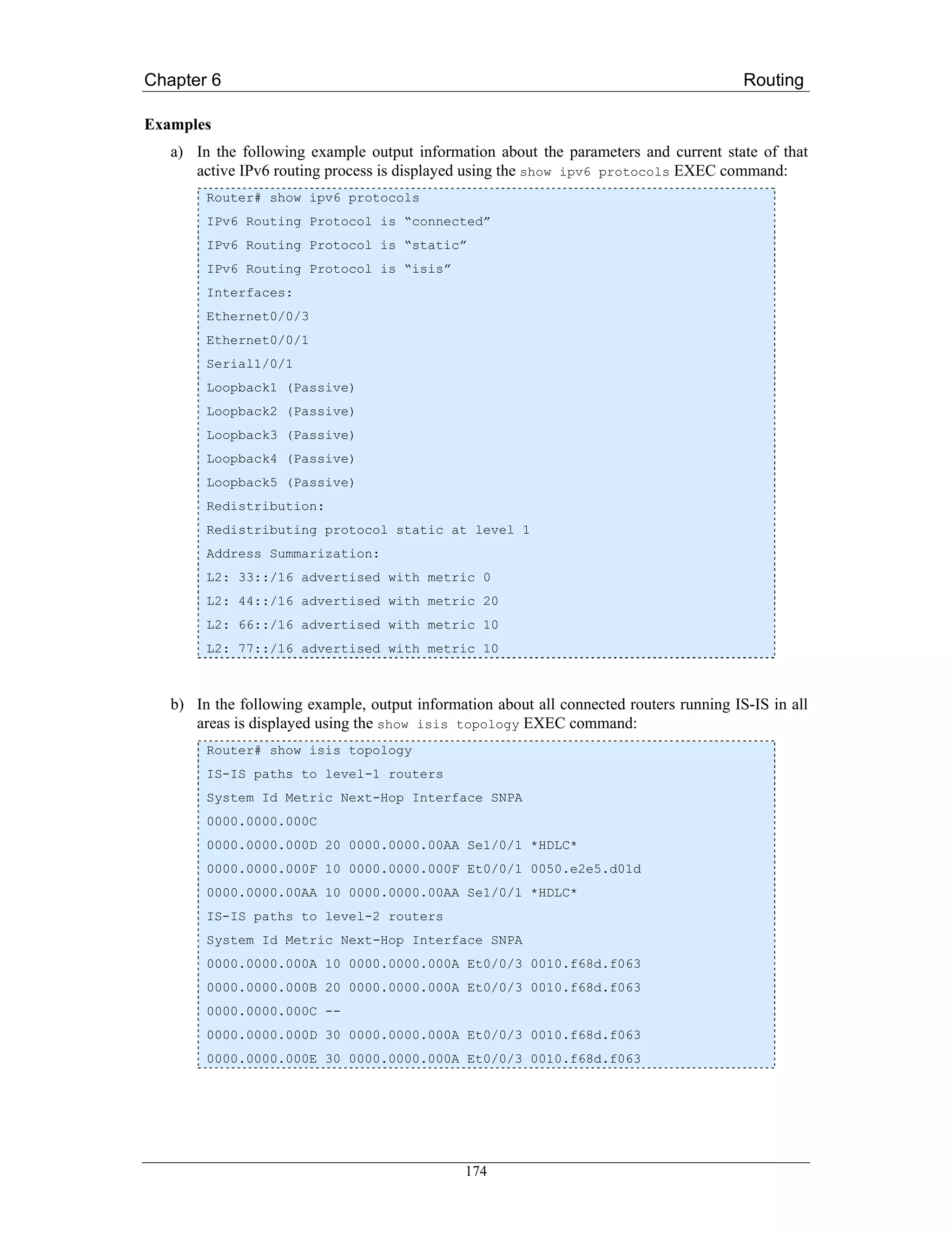
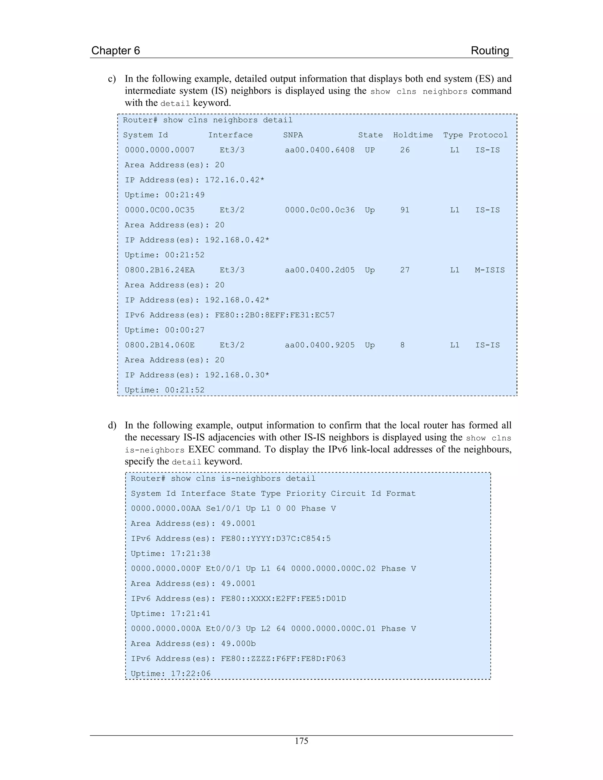
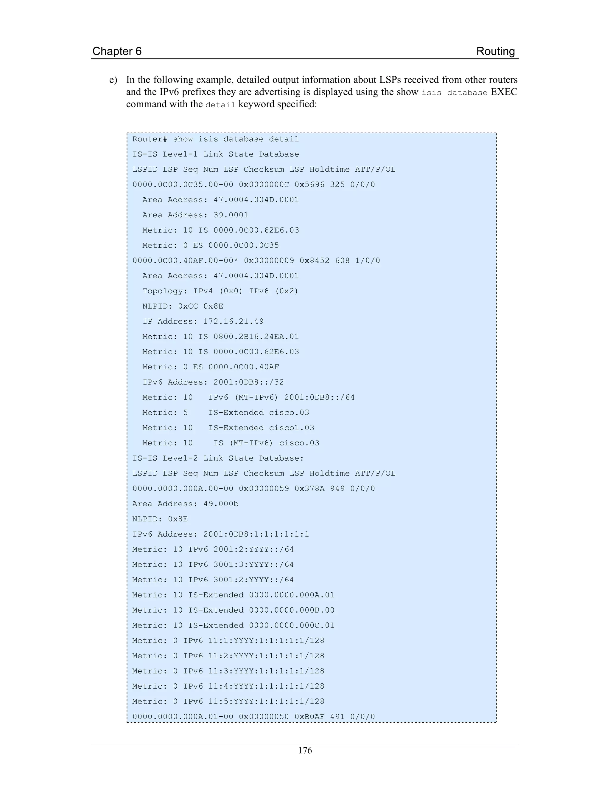
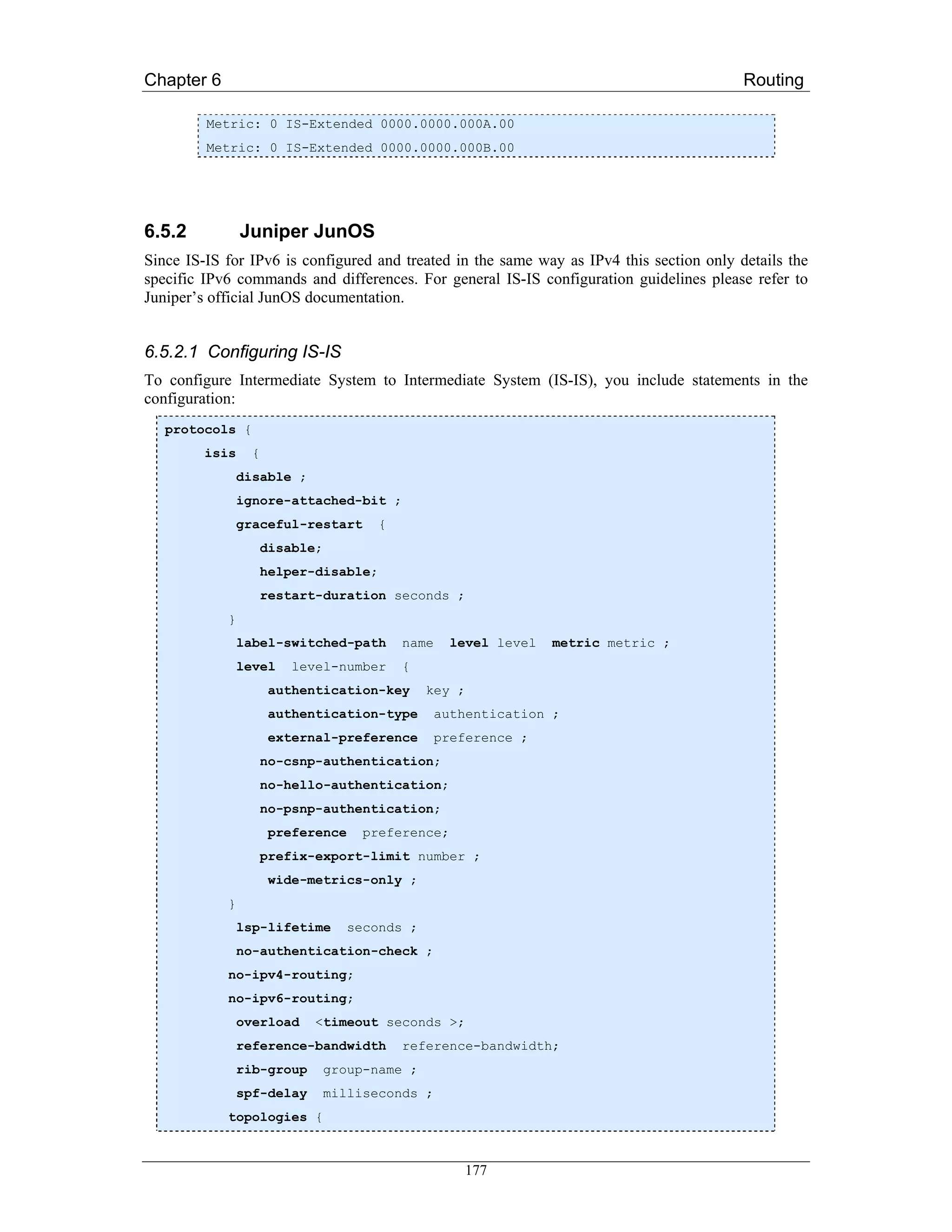
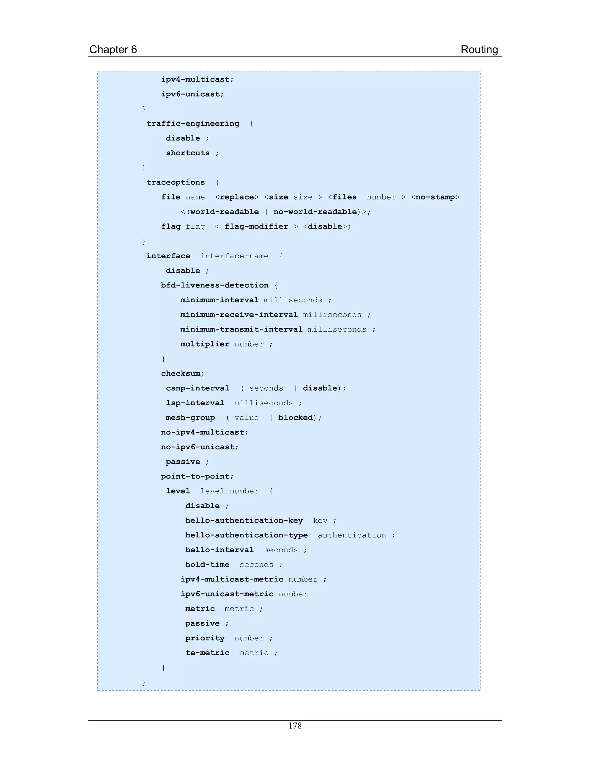
![Chapter 6 Routing
}
}
6.5.2.2 Disable IPv6 Routing
It is possible to disable Internet Protocol Version 6 (IPv6) routing for IS-IS. Disabling IPv6 routing
results in the following:
• Router does not advertise the NLPID for IPv6 in JunOS software 0th LSP fragment.
• Router does not advertise any IPv6 prefixes in JunOS software LSPs.
• Router does not advertise the NLPID for IPv6 in JunOS software hello packets.
• Router does not advertise any IPv6 addresses in JunOS software hello packets.
• Router does not calculate any IPv6 routes.
To disable IPv6 routing on the router, include the no-ipv6-routing statement:
[edit protocols]
isis {
no-ipv6-routing;
}
To re-enable IS-IS, delete the disable statement from the configuration:
[edit protocols]
user@host# delete isis no-ipv6-routing
6.5.2.3 Configure IS-IS IPv6 Unicast Topologies
You can configure IS-IS to calculate an alternate IPv6 unicast topology, in addition to the normal IPv4
unicast topology, and add the corresponding routes to inet6.0. The IS-IS interface metrics for the IPv4
topology can be configured independently of the IPv6 metrics. You can also selectively disable
interfaces from participating in the IPv6 topology while continuing to participate in the IPv4 topology.
This lets you exercise control over the paths that unicast data takes through a network.
To enable an alternate IPv6 unicast topology for IS-IS, include the ipv6-unicast statement:
[edit protocols]
isis {
topologies {
ipv6-unicast;
}
}
179](https://image.slidesharecdn.com/ipv6deployment-guide-110112200202-phpapp01/75/IPv6-Deployment-Guide-193-2048.jpg)
![Chapter 6 Routing
To configure a metric for an alternate IPv6 unicast topology, include the ipv6-unicast-metric
statement:
[edit protocols]
isis {
interface interface-name {
level level-number {
ipv6-unicast-metric number;
}
}
}
To disable alternate IPv6 unicast topologies for IS-IS, include the no-ipv6-unicast statement:
[edit protocols]
isis {
interface interface-name {
no-ipv6-unicast;
}
}
180](https://image.slidesharecdn.com/ipv6deployment-guide-110112200202-phpapp01/75/IPv6-Deployment-Guide-194-2048.jpg)
![Chapter 6 Routing
6.6 Implementing OSPF for IPv6
OSPF is a routing protocol for IP. It is a link-state protocol, as opposed to a distance-vector protocol
like RIP. Think of a link as being an interface on a networking device. A link-state protocol makes its
routing decisions based on the states of the links that connect source and destination machines. The
state of a link is a description of that interface and its relationship to its neighbouring networking
devices. The interface information includes the IPv6 prefix of the interface, the network mask, the type
of network it is connected to, the routers connected to that network, and so on. This information is
propagated in various type of link-state advertisements (LSAs).
A router’s collection of LSA data is stored in a link-state database. The contents of the database, when
subjected to the Dijkstra algorithm, result in the creation of the OSPF routing table. The difference
between the database and the routing table is that the database contains a complete collection of raw
data; the routing table contains a list of shortest paths to known destinations via specific router
interface ports.
OSPF version 3, which is described in RFC 2740 [RFC2740], supports IPv6. Implementing OSPFv3
for IPv6 expands on OSPFv2 to provide support for IPv6 routing prefixes. This section describes the
concepts and tasks you need to implement OSPFv3 for IPv6 on your network.
Note: OSPFv3 is a separate protocol from OSPFv2 and is therefore an IPv6-only routing protocol. If
you are running a dual-stack environment with OSPF you need separate routing processes for IPv4
and IPv6 (OSPFv2 and OSPFv3 respectively).
6.6.1 LSA Types for IPv6
Due to the fact that with IPv6 it is possible to configure many different IP addresses on one interface
LSA types for OSPv3 differ from those in OSPFv2 for IPv4.
The following list describes OSPFv3 LSA types, each of which has a different purpose:
• Router LSAs (Type 1)—Describes the link state and costs of a router’s links to the area. These
LSAs are flooded within an area only. The LSA indicates if the router is an Area Border
Router (ABR) or Autonomous System Boundary Router (ASBR), and if it is one end of a
virtual link. Type 1 LSAs are also used to advertise stub networks. In OSPF for IPv6, these
LSAs have no address information and are network protocol independent. In OSPF for IPv6,
router interface information may be spread across multiple router LSAs. Receivers must
concatenate all router LSAs originated by a given router when running the SPF calculation.
• Network LSAs (Type 2)—Describes the link-state and cost information for all routers attached
to the network. This LSA is an aggregation of all the link-state and cost information in the
network. Only a designated router tracks this information and can generate a network LSA. In
OSPF for IPv6, network LSAs have no address information and are network protocol
independent.
• Interarea-prefix LSAs for ABRs (Type 3)—Advertises internal networks to routers in other
areas (interarea routes). Type 3 LSAs may represent a single network or a set of networks
summarised into one advertisement. Only ABRs generate summary LSAs. In OSPF for IPv6,
addresses for these LSAs are expressed as prefix, prefix length instead of address, mask. The
default route is expressed as a prefix with length 0.
• Interarea-router LSAs for ASBRs (Type 4)—Advertise the location of an ASBR. Routers that
are trying to reach an external network use these advertisements to determine the best path to
the next hop. ASBRs generate Type 4 LSAs.
181](https://image.slidesharecdn.com/ipv6deployment-guide-110112200202-phpapp01/75/IPv6-Deployment-Guide-195-2048.jpg)
![Chapter 6 Routing
the higher router ID takes precedence. After the DR is elected, the BDR is elected the same way. A
router with a router priority set to zero is ineligible to become the DR or BDR.
When using NBMA in OSPF for IPv6, you cannot automatically detect neighbours. On an NBMA
interface, you must configure your neighbours manually using interface configuration mode.
6.6.3 Cisco IOS
Much of the OSPF for IPv6 feature is the same as in OSPF version 2. OSPF version 3 for IPv6, which
is described in RFC 2740, expands on OSPF version 2 to provide support for IPv6 routing prefixes and
the larger size of IPv6 addresses.
In OSPF for IPv6, a routing process does not need to be explicitly created. Enabling OSPF for IPv6 on
an interface will cause a routing process and its associated configuration, to be created.
Furthermore, in OSPFv3 on Cisco IOS, each interface must be enabled using commands in interface
configuration mode. This feature is different from OSPF version 2, in which interfaces are indirectly
enabled using the router configuration mode.
When using a non-broadcast multi-access (NBMA) interface in OSPF for IPv6, users must manually
configure the router with the list of neighbors. Neighboring routers are identified by their router ID.
In IPv6, users can configure many address prefixes on an interface. In OSPF for IPv6, all address
prefixes on an interface are included by default. Users cannot select some address prefixes to be
imported into OSPF for IPv6; either all address prefixes on an interface are imported, or no address
prefixes on an interface are imported.
Unlike OSPF version 2, multiple instances of OSPF for IPv6 can be run on a link.
6.6.3.1 Prerequisites
Before you enable OSPF for IPv6 on an interface, you should have an OSPF network strategy planned
for your IPv6 network. For example, you must decide whether multiple areas are required.
On the routers on which you want to use OSPFv3 you need to have IPv6 unicast routing enabled and
IPv6 address must be configured on the interfaces taking part in the routing process(es).
For the minimum required IOS version for features related to OSPFv3 routing please refer to:
http://www.cisco.com/univercd/cc/td/doc/product/software/ios123/123cgcr/ipv6_c/ftipv6s.htm#wp10 04964
6.6.3.2 Restrictions
Be careful when changing the defaults for commands used to enable OSPF for IPv6. Changing these
defaults will affect your OSPF for IPv6 network, possibly adversely.
Authentication is not yet supported in all IOS releases. It is currently only available in 12.3(4)T. The
feature will be more widely supported in OSPF for IPv6 in future releases.
6.6.3.3 Enabling OSPF for IPv6
To implement OSPFv3 on a Cisco IOS platform the protocol basically just needs to be enabled on an
interface with an IPv6 address with the following command:
Router(config-if)# ipv6 ospf process-id area area-id [instance instance-id]
183](https://image.slidesharecdn.com/ipv6deployment-guide-110112200202-phpapp01/75/IPv6-Deployment-Guide-197-2048.jpg)
![Chapter 6 Routing
Now an OSPFv3 process with the specified id is created and the protocol is enabled. The next two
sections on configuring NBMA interfaces and forcing SPF calculation are optional.
You can customize OSPF for IPv6 for your network, but you likely will not need to do so. The
defaults for OSPF in IPv6 are set to meet the requirements of most customers and features. If you must
change the defaults, refer to Cisco IPv4 configuration guide and Cisco IPv6 command reference to
find the appropriate syntax. Be careful when changing the defaults.
Example
The following example configures a (new) OSPFv3 process with id 1 and area 0.
Router(config-if)# ipv6 ospf 1 area 0
6.6.3.4 Configuring NBMA Interfaces
You can customize OSPF for IPv6 in your network to use NBMA interfaces. Before you configure
NBMA interfaces you must actually have your network configured as an NBMA network and
identified each neighbor. You cannot automatically detect neighbours, but must manually configure
your router to detect neighbours when using an NBMA interface. The commands to issue in the
respective interface’s configuration context are:
Router(config-if)# frame-relay map ipv6 ipv6-address dlci
[broadcast] [cisco] [ietf]
[payload-compression {packet-by-packet |
frf9 stac [hardware-options] | data-stream stac
[hardware-options]}]
The command defines the mapping between a destination IPv6 address and the data-link connection
identifier (DLCI) used to connect to the destination address.
To configure a neighbour use the following command:
Router(config-if)# ipv6 ospf neighbor ipv6-address
[priority number] [poll-interval seconds] [cost number]
[database-filter all out]
Examples
a) In the following example, the NBMA link is frame relay. For other kinds of NBMA links,
different mapping commands are used:
Router(config-if)# frame-relay map ipv6 FE80::A8BB:CCFF:FE00:C01 120
b) The router on the frame relay link above is configured as an OSPFv3 neighbour:
Router(config-if) ipv6 ospf neighbor FE80::A8BB:CCFF:FE00:C01
184](https://image.slidesharecdn.com/ipv6deployment-guide-110112200202-phpapp01/75/IPv6-Deployment-Guide-198-2048.jpg)
![Chapter 6 Routing
6.6.3.5 Clearing the Database and/or Forcing an SPF Calculation
Occasionally, when something was changed or for debugging purposes one might want to clear the
present routing table and/or force the OSPFv3 process to build it a new. This is done using the
following command, which is issued at the global configuration level:
Router # clear ipv6 ospf [process-id] {process | force-spf |
redistribution | counters [neighbor [neighbor-interface]]}
The command clears the OSPF state based on the OSPF routing process ID.
When the process keyword is used with the clear ipv6 ospf command, the OSPF database is
cleared and repopulated, and then the shortest path first (SPF) algorithm is performed. When the
force-spf keyword is used with the clear ipv6 ospf command, the OSPF database is not
cleared before the SPF algorithm is performed.
Example
The easiest way to do this is issuing the command without any more options:
Router# clear ipv6 ospf force-spf
6.6.3.6 Verifying OSPF for IPv6 Configuration and Operation
When debugging or verifying OSPFv3 configuration the show ipv6 ospf command comes in handy. It
may be issued with the interface keyword, even adding a specific interface name for which OSPF-
related information should be displayed. Or it may be used without an interface to display general
OSPFv3 information:
Router# show ipv6 ospf [process-id] [area-id]
interface [interface-type interface-number]
Router# show ipv6 ospf [process-id] [area-id]
Examples
a) This command displays OSPF-related interface information:
Router# show ipv6 ospf interface
b) This command displays general information about OSPF routing processes:
Router# show ipv6 ospf
6.6.3.7 Load Balancing in OSPF for IPv6
When a router learns multiple routes to a specific network via multiple routing processes (or routing
protocols), it installs the route with the lowest administrative distance in the routing table. Sometimes
the router must select a route from among many learned from the same routing process with the same
185](https://image.slidesharecdn.com/ipv6deployment-guide-110112200202-phpapp01/75/IPv6-Deployment-Guide-199-2048.jpg)
![Chapter 6 Routing
administrative distance. In this case, the router chooses the path with the lowest cost (or metric) to the
destination. Each routing process calculates its cost differently and the costs may need to be
manipulated in order to achieve load balancing.
OSPF performs load balancing automatically in the following way. If OSPF finds that it can reach a
destination through more than one interface and each path has the same cost, it installs each path in the
routing table. The only restriction on the number of paths to the same destination is controlled by the
maximum-paths command. The default maximum paths is 16, and the range is from 1 to 64.
6.6.4 Juniper JunOS
Though OSPFv3 for IPv6 and OSPFv2 are separate and different protocols all of the configuration
keywords available for both protocols are the same and have the same meaning. This section will
therefore only focus on the differences in their configuration.
6.6.4.1 Configure OSPFv3
To configure OSPF Version 3, you include the following statements. Note that not all configuration
statements available for IPv4 are present for IPv6 as well. Those that are however, are used in exactly
the same way.
protocols {
ospf3 {
disable;
export [ policy-names ];
external-preference preference;
graceful-restart {
disable;
helper-disable;
notify-duration seconds;
restart-duration seconds;
}
overload {
<timeout seconds>;
}
preference preference;
prefix-export-limit;
reference-bandwidth reference-bandwidth;
rib-group group-name;
spf-delay;
traceoptions {
file name <replace> <size size> <files number> <no-stamp>
<(world-readable | no-world-readable)>;
flag flag <flag-modifier> <disable>;
}
area area-id {
186](https://image.slidesharecdn.com/ipv6deployment-guide-110112200202-phpapp01/75/IPv6-Deployment-Guide-200-2048.jpg)
![Chapter 6 Routing
area-range network/mask-length <restrict>;
interface interface-name {
disable;
dead-interval seconds;
hello-interval seconds;
metric metric;
passive;
priority number;
retransmit-interval seconds;
transit-delay seconds;
}
nssa {
area-range network/mask-length <restrict>;
default-lsa {
default-metric metric;
metric-type type;
type-7;
}
(no-summaries | summaries)
}
stub <default-metric metric> <summaries | no-summaries>;
virtual-link neighbor-id router-id transit-area area-id {
disable;
dead-interval seconds;
hello-interval seconds;
retransmit-interval seconds;
transit-delay seconds;
}
}
}
}
6.6.4.2 Restrictions and Prerequisites
When you configure OSPFv3 on an interface, you must also include the family inet6 statement at
the [edit interfaces interface-name unit logical-unit-number] hierarchy level.
OSPFv3 does not support routing instances or authentication. It also only supports the no-forwarding
and vrf routing instance types.
At least one router on each logical link must be eligible to be the designated router for OSPFv3.
For OSPFv3, one OSPF-specific interface must be created per interface name configured under
OSPFv3. OSPFv3 does not allow interfaces to be configured by IP address.
187](https://image.slidesharecdn.com/ipv6deployment-guide-110112200202-phpapp01/75/IPv6-Deployment-Guide-201-2048.jpg)
![Chapter 6 Routing
Traffic engineering is not supported for OSPFv3.
6.6.4.3 Full Configuration Example
The following configuration was provided by FCCN, the Portuguese NREN. In this case there is only
one area, in which two of the router’s interfaces are active.
ospfv3@junos# show policy-options:
policy-statement default6 {
from {
protocol [ static direct ];
route-filter ::/0 exact;
}
then accept;
}
ospfv3@junos# show protocols:
ospf3 {
export default6;
area 0.0.0.0 {
interface lo0.0;
interface ge-0/0/0.5 {
priority 80;
}
interface ge-0/2/0.2 {
priority 80;
}
}
}
ospfv3@junos> show configuration interfaces ge-0/0/0 unit 5
vlan-id 5;
family inet {
address 193.137.0.x/yy;
}
family iso {
address 49.0001.0000.0000.0005.05;
}
family inet6 {
address 2001:690:xxxx:1::1/64;
}
188](https://image.slidesharecdn.com/ipv6deployment-guide-110112200202-phpapp01/75/IPv6-Deployment-Guide-202-2048.jpg)
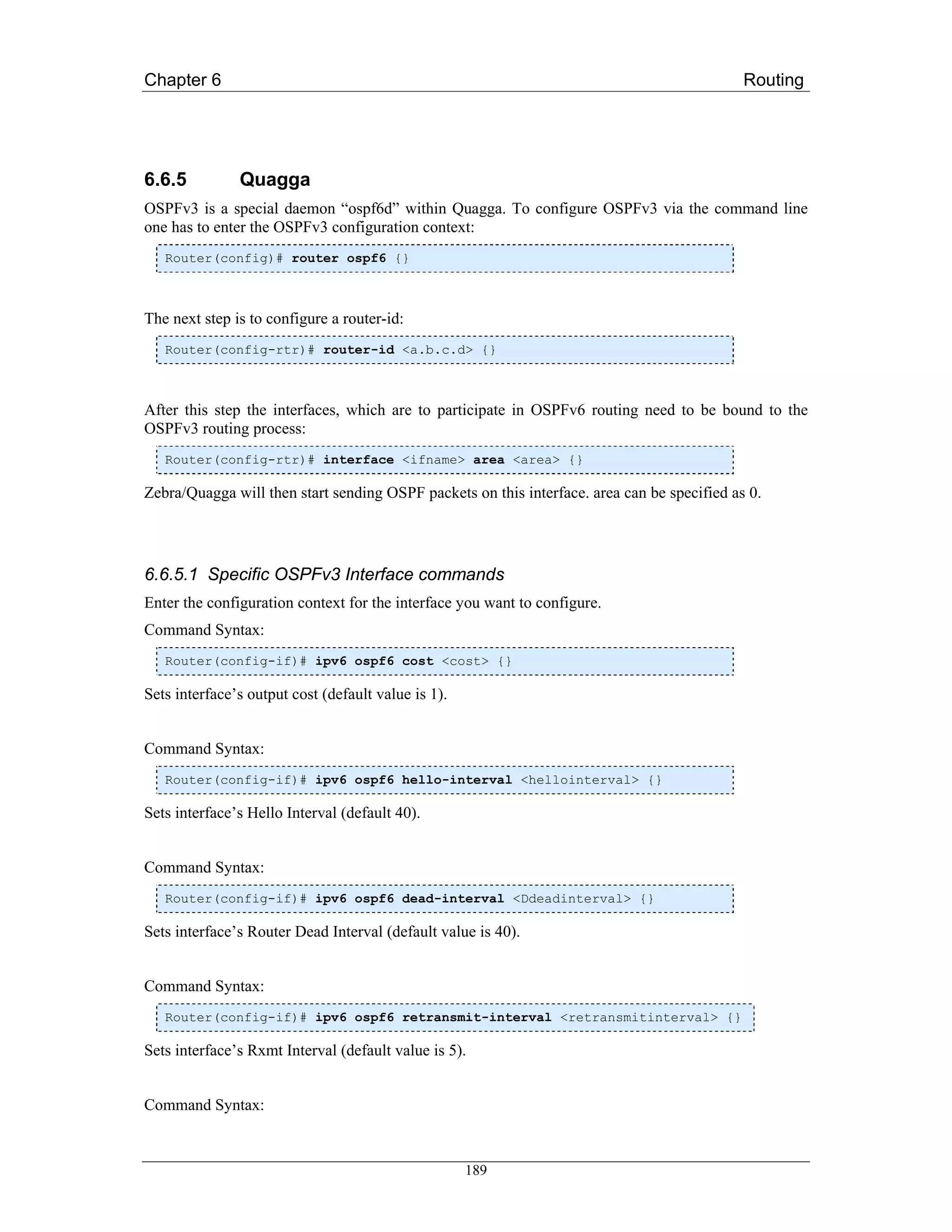
![Chapter 6 Routing
Router(config-if)# ipv6 ospf6 priority <priority> {}
Sets interface’s Router Priority (default value is 1).
Command Syntax:
Router(config-if)# ipv6 ospf6 transmit-delay <transmitdelay> {}
Sets interface’s Inf-Trans-Delay (default value is 1).
6.6.5.2 Route Redistribution
OSPFv3 on the Quagga platform offers the possibility to redistribute static, connected or RIPng routes.
The corresponding commands are entered in the ospf6 area context of the corresponding routing
process.
Router(config-rtr)# redistribute static {}
Router(config-rtr)# redistribute connected {}
Router(config-rtr)# redistribute ripng {}
6.6.5.3 Displaying OSPFv3 Information
Several show commands can be used to display OSPFv3 routing information to verify correct
configuration and router behaviour.
Command Syntax:
Router# show ipv6 ospf6 [<instance-id>] {}
instance-id is an optional OSPF instance ID. To see router ID and OSPF instance ID, simply type
“show ipv6 ospf6 “.
Command Syntax:
Router# show ipv6 ospf6 database {}
This command shows an LSA database summary. You can specify the type of LSA.
Command Syntax:
Router# show ipv6 ospf6 interface {}
Use this command to see OSPF interface configuration like for example costs.
Command Syntax:
190](https://image.slidesharecdn.com/ipv6deployment-guide-110112200202-phpapp01/75/IPv6-Deployment-Guide-204-2048.jpg)
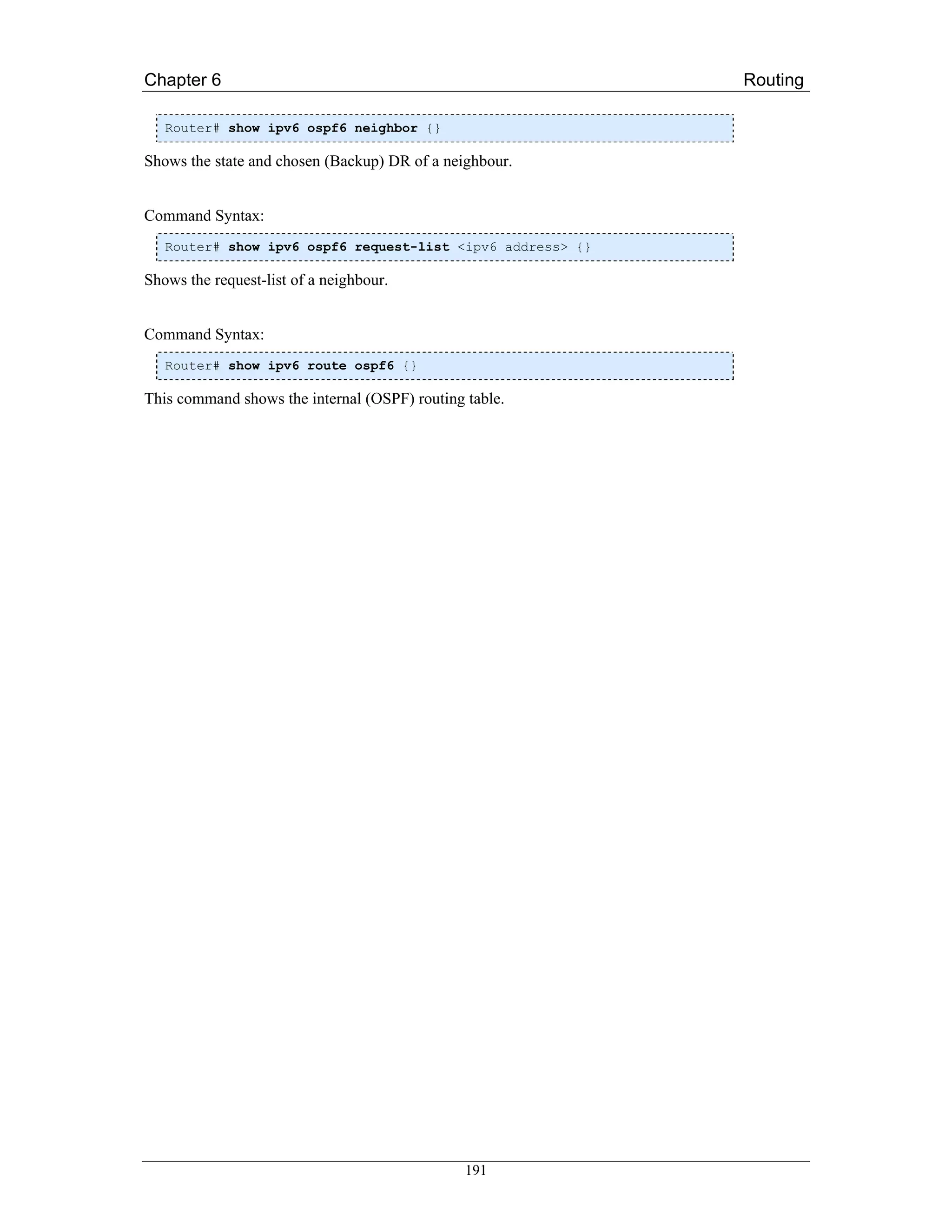
![Chapter 6 Routing
6.7 Implementing Multiprotocol BGP for IPv6
This section describes how to configure Multiprotocol Border Gateway Protocol (MBGP) for IPv6
[RFC2283],[BCKR05]. BGP is an Exterior Gateway Protocol (EGP) used mainly to connect separate
routing domains that contain independent routing policies (autonomous systems). Connecting to a
service provider for access to the Internet is a common use for BGP. BGP can also be used within an
autonomous system and this variation is referred to as internal BGP (iBGP). Multiprotocol BGP is an
enhanced BGP that carries routing information for multiple network layer protocol address families,
for example, IPv6 address family and for IP multicast routes. All BGP commands and routing policy
capabilities can be used with multiprotocol BGP.
6.7.1 Cisco IOS
Multiprotocol BGP is the supported Exterior Gateway Protocol (EGP) for IPv6. Multiprotocol BGP
extensions for IPv6 supports the same features and functionality as IPv4 BGP. IPv6 enhancements to
multiprotocol BGP include support for an IPv6 address family and network layer reachability
information (NLRI) and next hop (the next router in the path to the destination) attributes that use IPv6
addresses.
BGP uses a router ID to identify BGP-speaking peers. The BGP router ID is 32-bit value that is often
represented by an IPv4 address. By default, the Cisco IOS software sets the router ID to the IPv4
address of a loopback interface on the router. If no loopback interface is configured on the router, then
the software chooses the highest IPv4 address configured to a physical interface on the router to
represent the BGP router ID. When configuring BGP on a router that is enabled only for IPv6 (the
router does not have an IPv4 address), you must manually configure the BGP router ID for the router.
The BGP router ID, which is represented as a 32-bit value using an IPv4 address syntax, must be
unique to the BGP peers of the router.
6.7.1.1 Prerequisites
As with any IPv6 routing feature you must first enable ipv6 unicast-routing before configuring
Multiprotocol BGP.
For the minimum required IOS version for multiprotocol BGP features please refer to:
http://www.cisco.com/univercd/cc/td/doc/product/software/ios123/123cgcr/ipv6_c/ftipv6s.htm#wp10 04964
6.7.1.2 Enabling and Implementing Multiprotocol BGP for IPv6
When configuring multiprotocol BGP extensions for IPv6, you must create the BGP routing process,
configure peering relationships, and customize BGP for your particular network.
Note:The following sections describe the configuration tasks for creating an IPv6 multiprotocol BGP
routing process and associating peers, peer groups, and networks to the routing process. The following
sections do not provide in-depth information on customizing multiprotocol BGP because the protocol
functions the same in IPv6 as it does in IPv4.
Command syntax:
Router(config)# router bgp autonomous-system-number
192](https://image.slidesharecdn.com/ipv6deployment-guide-110112200202-phpapp01/75/IPv6-Deployment-Guide-206-2048.jpg)
![Chapter 6 Routing
The command configures a BGP routing process, and enters router configuration mode for the
specified routing process.
Router(config-router)# no bgp default ipv4-unicast
This command is used to disable the IPv4 unicast address family for the BGP routing process.
Otherwise routing information for the IPv4 unicast address family is advertised by default.
As mentioned above usually an IPv4 address configured on one of the interfaces is used as BGP router
id. You can optionally change/set this id with the following command:
Router(config-router)# bgp router-id ip-address
Note: Configuring a router id using the bgp router-id command resets all active BGP peering sessions.
As with IPv4 the next step is to configure BGP neighbors/peers. By default, neighbors that are defined
using the neighbor remote-as command in router configuration mode exchange only IPv4 unicast
address prefixes. To exchange other address prefix types, such as IPv6 prefixes, neighbors must also
be activated using the neighbor activate command in address family configuration mode for the other
prefix types, as shown for IPv6 prefixes.
The first step however is to add a neighbor in the context of previously created routing process:
Router(config-router)# neighbor ipv6-address remote-as
autonomous-system-number
The specified ipv6-address may be a unicast IPv6 address of any form, but configuring IPv6
multiprotocol BGP between two IPv6 routers (peers) using link-local addresses requires that the
interface for the neighbor be identified by using the update-source router configuration command,
and that a route map be configured to set an IPv6 global next hop. The update-source is defined in
the global BGP configuration context, after the neighbour was created:
Router(config-router)# neighbor ipv6-address update-source
interface-type interface-number
If there are multiple connections to the neighbor and you do not specify the neighbor interface by
using the interface-type and interface-number arguments in the neighbor update-source
command, a TCP connection cannot be established with the neighbor using link-local addresses.
Now enter the IPv6 address family:
Router(config-router)# address-family ipv6 [unicast]
The unicast keyword specifies the IPv6 unicast address family. By default, the router is placed in
configuration mode for the IPv6 unicast address family if the unicast keyword is not specified with
the address-family ipv6 command.
Within this context one can enable the neighbor to exchange prefixes for the IPv6 address family with
the local router.
Router(config-router-af)# neighbor ipv6-address activate
By default, route maps that are applied in router configuration mode using the neighbor route-map
command are applied to only IPv4 unicast address prefixes. Route maps for other address families
must be applied in address family configuration mode using the neighbor route-map command, as
shown for the IPv6 address family. The route maps are applied either as the inbound or outbound
193](https://image.slidesharecdn.com/ipv6deployment-guide-110112200202-phpapp01/75/IPv6-Deployment-Guide-207-2048.jpg)
![Chapter 6 Routing
routing policy for neighbors under the specified address family. Configuring separate route maps
under each address family type simplifies managing complicated or different policies for each address
family.
Router(config-router-af)# neighbor ipv6-address route-map map-name {in | out}
To configure a route map as it is needed when using a neighbour’s link local address in the BGP
configuration the special command set ipv6 next-hop is used in the route map configuration.
Router(config) # route-map map-name [permit | deny] [sequence-number]
Router(config-route-map)# match ipv6 address prefix-list prefix-list-name
Router(config-route-map)# set ipv6 next-hop ipv6-address [link-local-address]
The last command overrides the next hop advertised to the peer for IPv6 packets that pass a match
clause of a route map for policy routing.
The ipv6-address argument specifies the IPv6 global address of the next hop. It doesn’t need to be an
adjacent router.
The link-local-address argument specifies the IPv6 link-local address of the next hop. It must be
an adjacent router.
Note: The route map sets the IPv6 next-hop addresses (global and link-local) in BGP updates. If the
route map is not configured, the next-hop address in the BGP updates defaults to the unspecified IPv6
address (::), which is rejected by the peer.
If you specify only the global IPv6 next-hop address (ipv6-address argument) with the set ipv6
next-hop command after specifying the neighbor interface (interface-type argument) with the
neighbor update-source, the link-local address of the interface specified with the interface-type
argument is included as the next-hop in the BGP updates. Therefore, only one route map that sets the
global IPv6 next-hop address in BGP updates is required for multiple BGP peers that use link-local
addresses.
As with IPv4 several BGP peers for which the same route maps and prefix lists apply can be
configured as a peer group. This facilitates the configuration as well as optimizes the router’s handling
of the corresponding rules.
By default, peer groups that are defined in router configuration mode using the neighbor peer-group
command exchange only IPv4 unicast address prefixes. To exchange other address prefix types, such
as IPv6 prefixes, you must activate peer groups using the neighbor activate command in address
family configuration mode for the other prefix types, as shown for IPv6 prefixes.
Members of a peer group automatically inherit the address prefix configuration of the peer group.
IPv4 active neighbors cannot exist in the same peer group as active IPv6 neighbors. Create separate
peer groups for IPv4 peers and IPv6 peers.
Peer groups in general are defined in global BGP configuration mode. The following command creates
a multiprocotol BGP peer group:
Router(config)# router bgp autonomous-system-number
Router(config-router)# neighbor peer-group-name peer-group
Activating this peer group for IPv6 neighbours and adding neighbours to it must be done in the IPv6
address family configuration context. One can first add neighbors to a peer group and then later
activate all neighbours at once by activating the corresponding peer group.
194](https://image.slidesharecdn.com/ipv6deployment-guide-110112200202-phpapp01/75/IPv6-Deployment-Guide-208-2048.jpg)
![Chapter 6 Routing
Router(config-router)# address family ipv6 [unicast]
Router(config-router-af)# neighbor ipv6-address peer-group peer-group-name
Router(config-router-af)# neighbor {ip-address
| peer-group-name | ipv6-address} activate
Examples
a) The following example enables IPv6 globally, configures a BGP process and establishes a
BGP router ID. Also, the IPv6 multiprotocol BGP peer 2001:0DB8:0:CC00:: is configured
and activated.
ipv6 unicast-routing
!
router bgp 65000
no bgp default ipv4-unicast
bgp router-id 192.168.99.70
neighbor 2001:0DB8:0:CC00::1 remote-as 64600
address-family ipv6 unicast
neighbor 2001:0DB8:0:CC00::1 activate
b) The following example configures the IPv6 multiprotocol BGP peer
FE80::XXXX:BFF:FE0E:A471 over Fast Ethernet interface 0 and sets the route map named nh6
to include the IPv6 next-hop global address of Fast Ethernet interface 0 in BGP updates. The
IPv6 next-hop link-local address can be set by the nh6 route map (not shown in the following
example) or from the interface specified by the neighbor update-source router
configuration command (as shown in this example).
router bgp 65000
neighbor FE80::XXXX:BFF:FE0E:A471 remote-as 64600
neighbor FE80::XXXX:BFF:FE0E:A471 update-source fastethernet 0
address-family ipv6
neighbor FE80::XXXX:BFF:FE0E:A471 activate
neighbor FE80::XXXX:BFF:FE0E:A471 route-map nh6 out
route-map nh6 permit 10
match ipv6 address prefix-list cisco
set ipv6 next-hop 2001:5y6::1
ipv6 prefix-list cisco permit 2Fy2::/48 le 128
ipv6 prefix-list cisco deny ::/0
Note: If you specify only the global IPv6 next-hop address (ipv6-address argument) with the
set ipv6 next-hop command after specifying the neighbor interface (interface-type
argument) with the neighbor update-source command, the link-local address of the
interface specified with the interface-type argument is included as the next hop in the BGP
updates. Therefore, only one route map that sets the global IPv6 next-hop address in BGP
updates is required for multiple BGP peers that use link-local addresses.
195](https://image.slidesharecdn.com/ipv6deployment-guide-110112200202-phpapp01/75/IPv6-Deployment-Guide-209-2048.jpg)
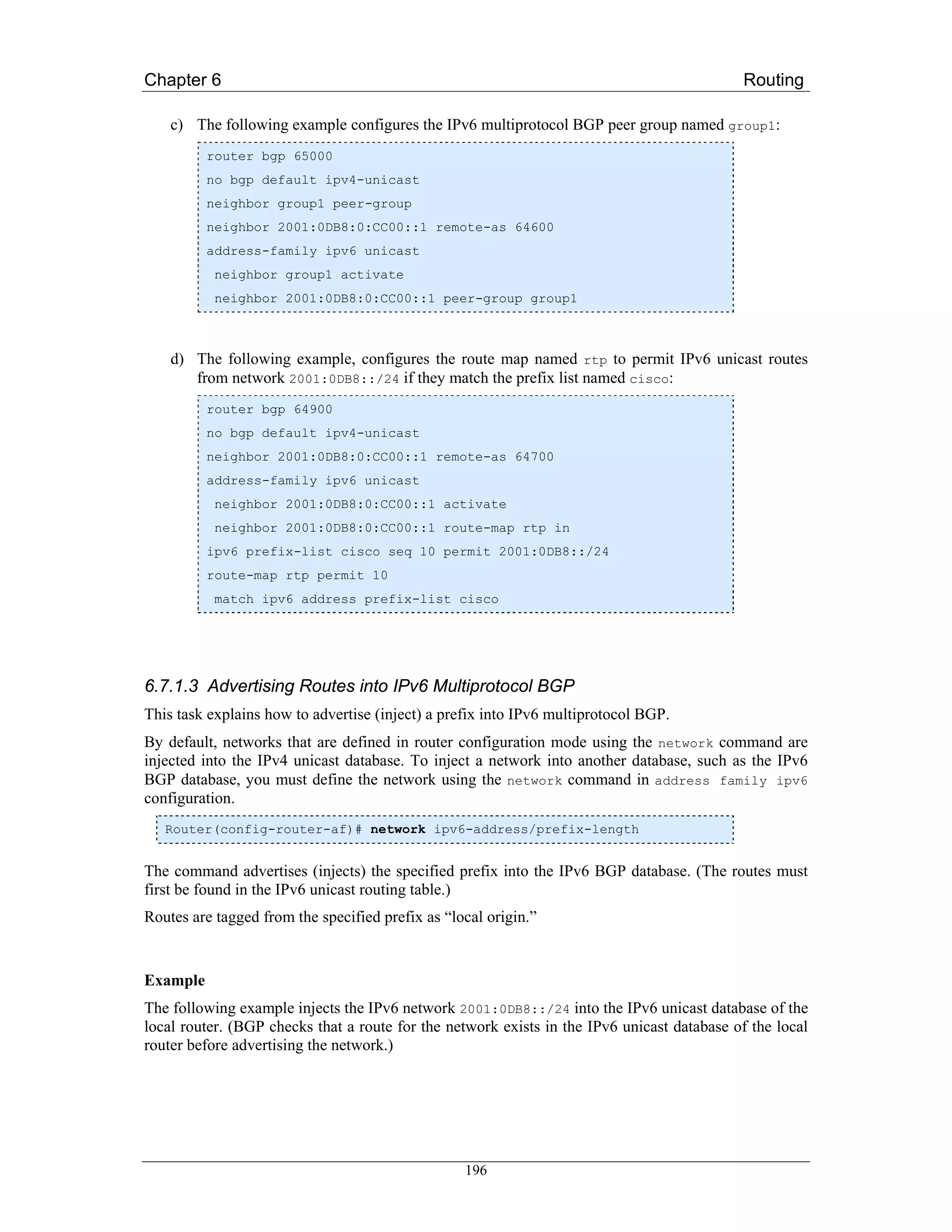
![Chapter 6 Routing
router bgp 65000
no bgp default ipv4-unicast
address-family ipv6 unicast
network 2001:0DB8::/24
6.7.1.4 Redistributing Prefixes into IPv6 Multiprotocol BGP
This task explains how to redistribute (inject) prefixes from another routing protocol into IPv6
multiprotocol BGP.
To accomplish this task the redistribute command is used in the address-family ipv6
configuration context of the corresponding BGP process.
Router(config-router-af)# redistribute protocol [process-id]
[level-1 | level-1-2 | level-2] [metric metric-value]
[metric-type {internal | external}] [route-map map-name]
The command specifies the routing protocol from which prefixes should be redistributed into IPv6
multiprotocol BGP.
The protocol argument can be one of the following keywords: bgp, connected, isis, rip or static.
Note: The connected keyword refers to routes that are established automatically by IPv6 having been
enabled on an interface.
Example
The following example redistributes RIP routes into the IPv6 database of the local router:
router bgp 64900
no bgp default ipv4-unicast
address-family ipv6 unicast
redistribute rip
6.7.1.5 Advertising IPv4 Routes Between IPv6 BGP Peers
This task explains how to advertise IPv4 routes between IPv6 peers. If an IPv6 network is connecting
two separate IPv4 networks, it is possible to use IPv6 to advertise the IPv4 routes. Configure the
peering using the IPv6 addresses within the IPv4 address family. Set the next hop with a static route or
with an inbound route map because the advertised next hop will usually be unreachable. Advertising
IPv6 routes between two IPv4 peers is also possible using the same model.
Example
The following example advertises IPv4 routes between IPv6 peers when the IPv6 network is
connecting two separate IPv4 networks. Peering is configured using IPv6 addresses in the IPv4
address family configuration mode. The inbound route map named rmap sets the next hop because the
advertised next hop is likely to be unreachable.
197](https://image.slidesharecdn.com/ipv6deployment-guide-110112200202-phpapp01/75/IPv6-Deployment-Guide-211-2048.jpg)
![Chapter 6 Routing
router bgp 65000
!
neighbor 6peers peer-group
neighbor 2000:yyyy::2 remote-as 65002
address-family ipv4
neighbor 6peers activate
neighbor 6peers soft-reconfiguration inbound
neighbor 2000:yyyy::2 peer-group 6peers
neighbor 2000:yyyy::2 route-map rmap in
!
route-map rmap permit 10
set ip next-hop 10.21.8.10
6.7.1.6 Verifying IPv6 Multiprotocol BGP Configuration and Operation
Various show and debug commands may be used to verify IPv6 Multiprotocol BGP operation and
configuration. The show command can be used as an unprivileged user.
Command syntax:
The following comannd displays entries in the IPv6 BGP routing table:
Router> show bgp ipv6 [ipv6-prefix/prefix-length]
[longer-prefixes] [labels]
To view a summary of all BGP connections, use the following command:
Router> show bgp ipv6 summary
IPv6 BGP dampened routes may be displayed with this command:
Router> show bgp ipv6 dampened-paths
For the debug command one needs higher privilege levels.
Router# debug bgp ipv6 dampening [access-list-name]
[prefix-list prefix-list-name]
The command displays debugging messages for IPv6 BGP dampening packets.
If no prefix list is specified, debugging messages for all IPv6 BGP dampening packets are displayed.
Router# debug bgp ipv6 updates [ipv6-address]
[prefix-list prefix-list-name] [in | out]
The command can be used to display debugging messages for IPv6 BGP update packets.
If an ipv6-address argument is specified, debugging messages for IPv6 BGP updates to the specified
neighbor are displayed.
Use the in keyword to display debugging messages for inbound updates only.
Use the out keyword to display debugging messages for outbound updates only.
198](https://image.slidesharecdn.com/ipv6deployment-guide-110112200202-phpapp01/75/IPv6-Deployment-Guide-212-2048.jpg)
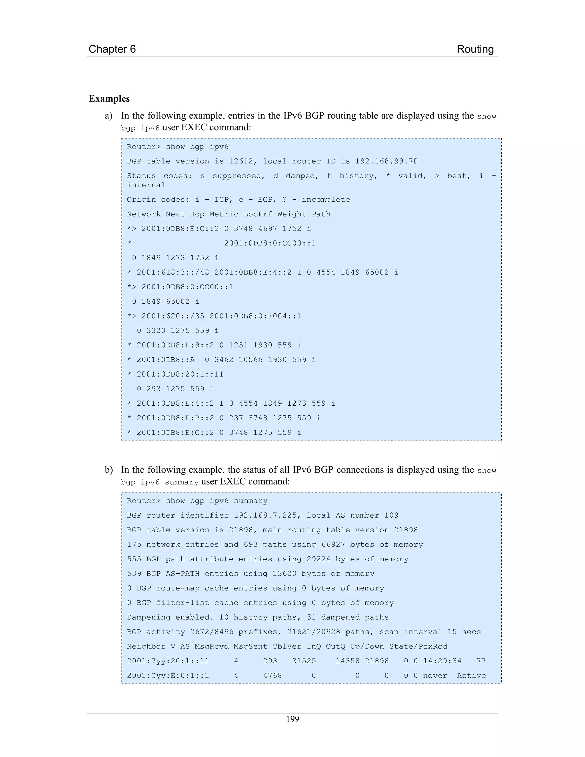
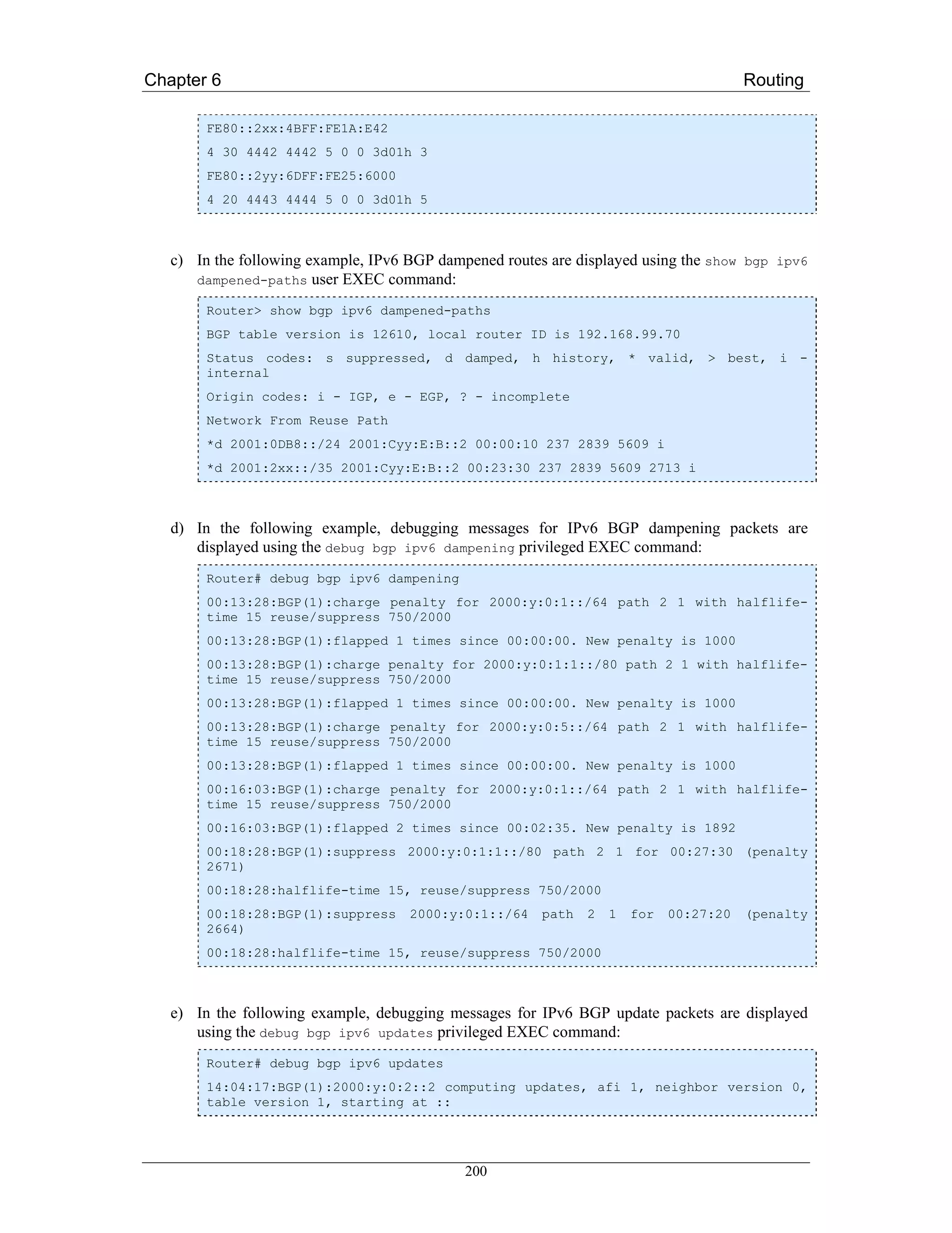
![Chapter 6 Routing
14:04:17:BGP(1):2000:y:0:2::2 update run completed, afi 1, ran for 0ms,
neighbor version 0, start version 1, throttled to 1
14:04:19:BGP(1):sourced route for 2000:0:0:2::1/64 path #0 changed (weight
32768)
14:04:19:BGP(1):2000:y:0:2::1/64 route sourced locally
14:04:19:BGP(1):2000:y:0:2:1::/80 route sourced locally
14:04:19:BGP(1):2000:y:0:3::2/64 route sourced locally
14:04:19:BGP(1):2000:y:0:4::2/64 route sourced locally
14:04:22:BGP(1):2000:y:0:2::2 computing updates, afi 1, neighbor version 1,
table version 6, starting at ::
14:04:22:BGP(1):2000:y:0:2::2 send UPDATE (format) 2000:0:0:2::1/64, next
2000:0:0:2::1, metric 0, path
14:04:22:BGP(1):2000:y:0:2::2 send UPDATE (format) 2000:0:0:2:1::/80, next
2000:0:0:2::1, metric 0, path
14:04:22:BGP(1):2000:y:0:2::2 send UPDATE (prepend, chgflags:0x208)
2000:0:0:3::2/64, next 2000:0:0:2::1, metric 0, path
14:04:22:BGP(1):2000:y:0:2::2 send UPDATE (prepend, chgflags:0x208)
2000:0:0:4::2/64, next 2000:0:0:2::1, metric 0, path
6.7.2 Juniper JunOS
To enable MBGP to carry network layer reachability information (NLRI) for IPv6 address family,
include the family inet6 statement:
family inet6 {
(any | labeled-unicast | multicast | unicast) {
prefix-limit {
maximum number;
teardown <percentage> <idle-timeout (forever | minutes)>;
}
rib-group group-name;
}
}
6.7.3 Quagga/Zebra
bgpd supports Multiprotocol Extension for BGP. So if remote peer supports the protocol, bgpd can
exchange IPv6 and/or multicast routing information.
Traditional BGP does not have the feature to detect remote peer’s capability whether it can handle
other than IPv4 unicast routes. This is a big problem using Multiprotocol Extension for BGP to
operational network. [RFC2842] proposing a feature called Capability Negotiation. bgpd use this
Capability Negotiation to detect remote peer’s capabilities. If the peer is only configured as IPv4
unicast neighbor, bgpd does not send these Capability Negotiation packets.
201](https://image.slidesharecdn.com/ipv6deployment-guide-110112200202-phpapp01/75/IPv6-Deployment-Guide-215-2048.jpg)
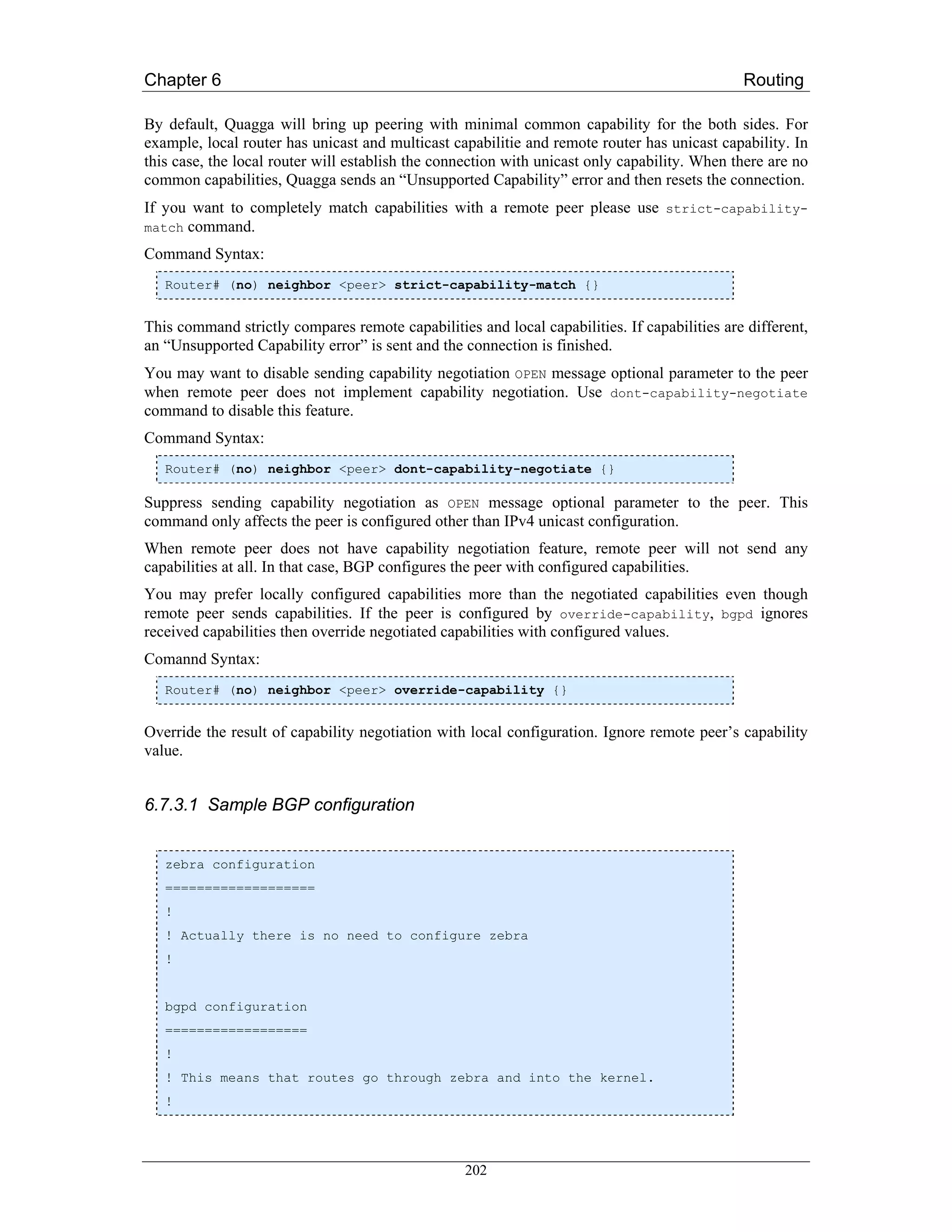
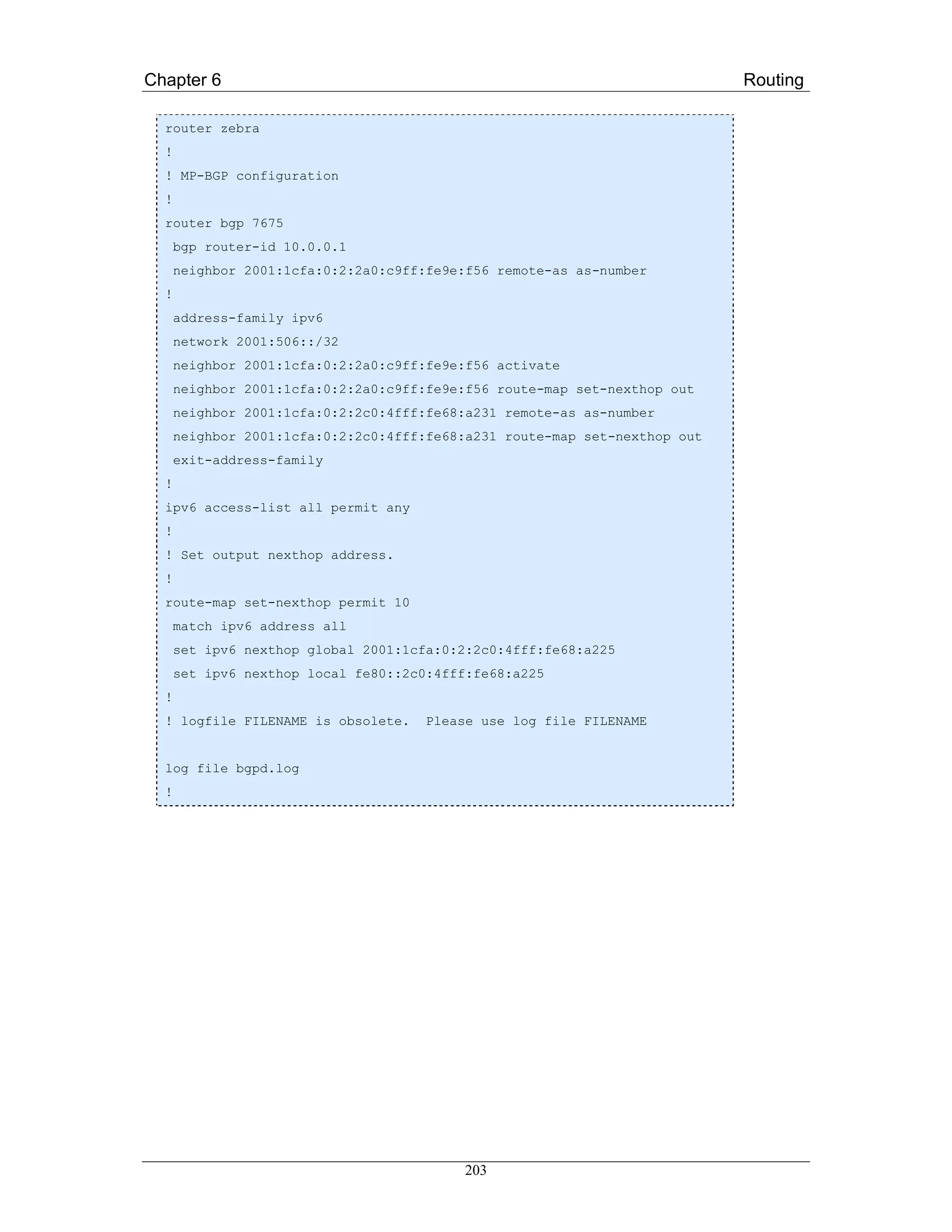
![Chapter 7 Network Management
Chapter 7
Network Management
Network management and monitoring is a critical part of operating any production quality network,
whatever the nature of the network. It is one of the essential building blocks of the 6NET network, and
must be so for any IPv6 public network, especially in the Internet service provider area. If IPv6
backbone networks are not subject to the same (or even an improved) standard of management and
monitoring as existing IPv4 networks, the existing IPv4 user base will be unwilling to migrate to IPv6.
Network Management covers many areas (also called network segments) of the network. Usual
classification distinguishes Local area Networks (LAN) from Metropolitan (MAN) and Wide Area
Networks (WAN). In this regard sets of very different functions have to be provided to the manager,
from straightforward monitoring of link status, to traffic statistics gathering and analysis. These sets
could roughly be classified in two categories: those needed for day to day network control operations
and those dedicated to network behaviour analysis. The latter allows the manager to optimise the
network or parts of it and to schedule the necessary evolutions.
This chapter brings together all the important network monitoring and management work conducted
by the network management workpackage of 6NET. This chapter is designed as a “cookbook”,
summarising the issues required for managing and monitoring an IPv6 network, and suggests
appropriate tools that can be used to support the network management and monitoring function. The
end result should be that this will be both a useful guide to designers of new IPv6 networks, and as a
reference for more experienced network managers.
7.1 Management protocols and MIBs in the standardisation
process
As the main management standard used for IPv4 networks is SNMP (Simple Network Management
Protocol), [RFC3416], it was an obvious goal to pursue to also make SNMP management available for
and via IPv6. This section focuses on SNMP for IPv6, the corresponding MIBs (Management
Information Base) and standardisation process and also gives a brief history on the evolution of the
SNMP protocol in general.
7.1.1 SNMP for IPv6
Today many network vendors (6WIND, CISCO, HITACHI, JUNIPER etc.) support SNMP over IPv6
and can be monitored in an IPv6-only environment. One could note that equipment not supporting
SNMP over IPv6 can be managed over IPv4 as most IPv6 networks are running dual stack.
The number of SNMP applications able to poll remote SNMP agents over IPv6 remains low. Most of
the tools today use the netSNMP open source SNMP library. Recently however, some integrated
204](https://image.slidesharecdn.com/ipv6deployment-guide-110112200202-phpapp01/75/IPv6-Deployment-Guide-218-2048.jpg)
![Chapter 7 Network Management
management platforms (HP Openview, Ciscoworks 2000) have also become, or are in the process of
becoming, IPv6 capable and serious progress has been made towards the support of SNMP functions,
even if the transport remains IPv4 in most cases.
7.1.2 MIBs
There are almost one hundred MIBs to check, to verify if they could be used to manage IPv6
networks. Some will have to be further developed to support IPv6.
7.1.2.1 The Textual Conventions
In 1998, a textual convention was defined for IPv6 addresses only. But this implied the partition of
IPv4 and IPv6 management information bases, in other words, it would take double the effort to get all
MIBs ready for both versions of IP. Fortunately, another approach is underway based on a “unified
MIB convention” where the same MIB can handle both IPv4 and IPv6. To be able to achieve this, the
address data structure had to be changed. But it is worth the effort.
This new convention defines an IP address as a structure {inetAddressType, inetAddress}, where:
• inetAddressType is an INTEGER which specifies if the following address is, for example, an
IPv4 or IPv6 one, and
• inetAddress is defined as an OCTET STRING(SIZE(0...255)), in order to be able to save the
value of an IPv4 or IPv6 address, as the value of a DNS name (cf. RFC 2851 [RFC2851]
updated by RFC 3291 [RFC3291]).
7.1.2.2 The Evolution of the MIBs
In 1996, the MIB II was updated in order to manage IPv4 networks. It was defined by the RFC 2011
(IP MIB) [RFC2011], RFC 2012 (TCP MIB) [RFC2012], RFC 2013 (UDP MIB) [RFC2013] and RFC
2096 (IP forwarding MIB) [RFC2096]. Three groups were defined: ip, tcp and udp. Each group
contains simple objects and tables (see Figure 7-1).
In 2002, the approach, illustrated in Figure 7-1, unified all the tables: ipAddrTable became
ipAddressTable, ipNetToMediaTable became ipNetToMediaTable, and all the simple objects defined
in the IPv4 MIB II became the ipIfStatsTable. Similarly, tcpConnTable became tcpConnectionTable,
and udpTable became udpListenerTable. It must be noticed that, in addition to this table, issued from
the IPv4 management architecture, new tables were defined like the ipv6InterfaceTable. RFC 2851
[RFC2851] (now updated with RFC 3291 [RFC3291] and RFC 4001 [RFC4001]) describes textual
conventions to represent both versions of IP in MIBs. The existing MIBs (RFC 2011, 2012, 2013 and
2096) were updated following this new textual convention. Respectively, these are RFC 2011bis
[RFC2011bis] (currently in the RFC editors queue), RFC 4022 [RFC4022], RFC 4113 [RFC4113],
and RFC 2096bis [RFC2096bis] (also still in the RFC editors queue).
205](https://image.slidesharecdn.com/ipv6deployment-guide-110112200202-phpapp01/75/IPv6-Deployment-Guide-219-2048.jpg)
![Chapter 7 Network Management
RFC 2851 RFC 3291 RFC 4001
RFC 2011 Draft-RFC2011-update10
RFC 2012 RFC4022
RFC 2013 RFC4113
RFC 2096 Draft-RFC2096-update07
Nov 1996 June 2002 May 2002 Feb 2005 Sept 2005
Figure 7-1 The Unified MIB II
(Numbers in parenthesis are oids)
7.1.3 The Other Standards
The SNMP standard was mainly used for the monitoring and fault management. Some other standards
were defined to satisfy the need of configuration and AAA (Authentication, Authorization and
Accounting) [RFC3539]. Those standards are COPS [RFC2748], WBEM (Web-Based Enterprise
Manager) [WBEM] for the configuration point of view, RADIUS [RFC3162] and Kerberos V
[RFC1510] for the AAA.
COPS and WBEM are available for IPv6 networks. The protocols themselves and their data models or
policies are already defined to be able to manage such networks. But it seems that no implementation
of those standards exist.
RADIUS was defined upon IPv6 in 2001 (RFC 3162). But as experience has shown that it cannot be
used in large scale network, a new protocol was defined by the IETF called DIAMETER. However,
there is IPv6 support in the RADIUS implementations ‘Radiator’ and ‘FreeRadius’.
DIAMETER has been published as RFC 3588 [RFC3588]. An implementation already exists, from
SUN Microsystems, based on the 7th version of the draft. A new one is under development within the
IST Moby Dick project, defined upon the 10th version of the draft. An open source DIAMETER
implementation project has also been started at SourceForge (for more information visit
http://sourceforge.net/projects/diameter/), which aims to produce a reference implementation of the
DIAMETER protocol.
KERBEROS V was partly implemented upon IPv6 since its 1.2 version, by the Massachusetts Institute
of Technology.
7.1.4 Flow Monitoring (IPFIX, Netflow...)
Netflow is a flow-based traffic accounting protocol defined by Cisco Systems. It is widely used to
support various applications such as usage-based billing, traffic analysis, or capacity planning. The
latest version, Netflow v9, is used as a basis for the IPFIX (IP Flow Information eXport) protocol that
is currently being standardized in the IETF (see [Cla05]). Only version 9 of Netflow is designed to
export IPv6 flows towards the Netflow collector.
IPv6 support in Netflow v9 is now available in the 12.3T CISCO IOS train. But the transport used for
the data export is still over IPv4 only. On the GSR series Netflow v9 is implemented but is not yet
able to export IPv6 flows.
206](https://image.slidesharecdn.com/ipv6deployment-guide-110112200202-phpapp01/75/IPv6-Deployment-Guide-220-2048.jpg)
![Chapter 7 Network Management
Netflow Collectors are also available for IPv6 either from Cisco (NFCv5.0) or from academic
organizations (UTC, France).
7.1.5 Management of IPv6 Protocols and Transition Mechanisms
IPv6 is a new protocol and with it many services are being deployed. The network management entity
has to be aware of the impact on network management when deploying these new services. For
instance, transition mechanisms between IPv4 and IPv6 should be considered in the management
infrastructure. Some work has already been done regarding the management of the IPv6/IPv4
coexistence protocols. RFC 4087 [RFC4087] describes a MIB for tunnel management.
Section 9.4 gives some recommendations for secured management of transition mechanisms but
targets mostly security aspects of the different transition protocols rather than the management
techniques.
Nevertheless, it should be noted that in general, there is little standardization effort made for the
management of new services coming along with IPv6, as most of the work is concentrated on having
the same level of management for IPv6 as for IPv4.
7.1.6 Remaining Work to be Done
As we can see, for the short-term the main problem is to get similar management standards for IPv6 as
those for IPv4.
The implementation of the unified MIBs for TCP, UDP and BGP becomes more urgent. Today many
manufacturers implement private MIBs based on RFC 2465 [RFC2465] or the drafts updating RFCs
2011, 2012 and 2013. The transport of SNMP over IPv6 is no longer a problem as most network
equipment supports this feature today.
7.2 Network Management Architecture
In this section we describe the basic ideas of network management architecture design. It is aimed at
giving help to anyone starting an IPv6 network, to help understand how to setup its management
entities and information flows between these entities.
7.2.1 Conceptual Phase
7.2.1.1 Network Segments and Boundaries
Before deploying a new network, it is wise to think how to structure the network in order to facilitate
the management. For instance in the 6NET project, three network segments were defined: a core
network, access networks and user/site networks. Once the management boundaries are clearly
defined, other elements can be added like VLANs, DMZ, intranets etc.
The other goal to achieve during this preliminary step is to clarify the domains responsibilities for
every entity involved in the network management. For instance, in the example of 6NET, the core
network was under 6NET NOC responsibility, the access networks under the NREN responsibility and
the user/site network under the responsibility of the network administrator of the site.
7.2.1.2 Information Flows
After the preliminary planning stages it is useful to consider the information flows between the entities
responsible for each domain to get a clear understanding on what information is needed to manage the
207](https://image.slidesharecdn.com/ipv6deployment-guide-110112200202-phpapp01/75/IPv6-Deployment-Guide-221-2048.jpg)
![Chapter 7 Network Management
domain, who is supposed to provide this information and who should receive it. Usually, the operation
of the links is in the charge of the entity closer to the core, with every entity being responsible for its
interfaces which are connected to links which have terminations in different domains.
From this information, operational procedures can be designed and written down (as an example, the
reader can refer to deliverable D6.1.2 [D6.1.2], where this “theoretical exercise” has been applied to
the 6NET network management). Looking back after completion of the project it can be stated that the
process was useful and efficient. For many months nobody complained about the way the network –
mainly the core network – was managed. Additionally, operational procedures for implementing test
phases for experiments and tests were identified and implemented. This was not easy since the goal
was to accommodate requirements both for production-like traffic and test constraints.
7.2.1.3 Security Aspects
One of the most complex things to decide is the security of management information and procedures.
There are several things to take into account in this area:
• The security of the management information itself and the priority of its traffic.
The management information should stay under the network administrator’s control. Part of
this information is usually not publicly available; it is reserved for administrators to control
the normal network behaviour or to gather statistics data on the traffic flows… When there is
congestion or an overload in (part of) the network, then it is efficient to have predefined the
class of traffic the management information belongs to. It is a good way to insure the
management information remains available to the administrator when the traffic is slowed
down for whatever reason.
• The security of the operational procedures.
Operational procedures are defined so the network management information and the access to
the network resources are accessible almost at anytime. For general outage there is no real
solution but these situations are becoming rare at least in developed countries. The operational
procedures should be designed to take into account unusual events so the administrator knows
in advance what he has to do (urgent actions to take, who to warn etc.). These procedures are
usually only known by a restricted group of people and are written down.
• The security of the network equipments and their access.
Access to the network equipments is obviously not granted to anyone. Security measures have
to be implemented adequately. Moreover, a backup way (or ways) to access the network
equipments in case of outage have to be predefined (for instance the IPv4 connectivity can be
used to access dual stacked equipments when IPv6 routing is broken). Usually, for critical
resources, phones lines or ISDN allow access to the equipment in case of outage. These
accesses are part of the network management; they should be considered during the
conceptual phase of building the network and then be checked on a regular basis when the
network has been put into operation.
7.2.1.4 Maintenance
Maintenance procedures and their reserved time slots should be defined in advance so a wide set of
people knows about them. Regular maintenance is usually scheduled out of working hours, to avoid
disturbing the production traffic. Other maintenance procedures are for emergency cases (e.g.
outages). They have to be foreseen in the operational procedures.
208](https://image.slidesharecdn.com/ipv6deployment-guide-110112200202-phpapp01/75/IPv6-Deployment-Guide-222-2048.jpg)
![Chapter 7 Network Management
7.2.1.5 Management Information Accessible to Users
Various experiences have shown that it is very important to provide the users of the network with
some management information. It is efficient since the user (including an administrator from another
network segment/domain) can quickly understand where a problem comes from and try to get in touch
with the appropriate person or entity, instead of asking people that cannot help in solving a problem
and wasting time unnecessarily.
For this use, tools to provide management information have to be chosen and a relevant subset of the
information should be selected. To this end, in the 6NET project a set of looking glasses, weather
maps etc., were implemented. They allowed any user to understand with a simple click how the
network performed and in case of problems in what part of the network the problem occurred.
Obviously these facilities are not restricted to large networks, but can be applied to any LAN with real
benefits. The only thing that changes in this case is the nature of management information the users
can obtain.
7.2.1.6 Transition Mechanisms and Services
Most of the above applies with no major differences to either IPv4 or IPv6 networks. What are specific
to IPv6 are the so-called transition mechanisms. In fact they are meant to provide internetworking
between IPv4 and IPv6 resources. These mechanisms can be seen as services offered to the users.
They need the administrator to pay attention to them depending on how they are implemented,
managed and the secured. For instance, designing a 6to4 service requires decisions on which users
should be allowed to use the service, where the 6to4 gateways are installed, whether there are any 6to4
relays available in the network or if another network’s relays are allowed, At the present time, it is not
yet completely clear how to manage such services and what information is relevant for the
administrator. Since most of these mechanisms are based upon encapsulation techniques, the security
issues are those associated with these kinds of well known mechanisms in IPv4. More information is
available in 6NET deliverable D6.2.2v2 [D6.2.2] on operational procedures for secured management
with transition mechanisms.
7.2.2 Implementation Phase - Management Tools Set
Once all the steps of the conceptual phase have been clearly understood and executed it is time to
select the appropriate tools to gather the information needed as defined during the planning. To this
respect the reader can refer to D6.2.4 [D6.2.4] where the management and monitoring tools we gained
experience with are documented. A subset of those tools used for the management in the different
segments of the 6NET network, is described in the following sections
209](https://image.slidesharecdn.com/ipv6deployment-guide-110112200202-phpapp01/75/IPv6-Deployment-Guide-223-2048.jpg)
![Chapter 7 Network Management
7.3 Management Tools Deployed in 6NET
There are many tools to manage and monitor IPv6 networks. The management needs are not the same
in the different parts of the network as discussed in the previous sections. For this reason this part of
the chapter classifies the management tools according to the part of the network they best apply to (i.e.
LAN or WAN).
In this section the following tools for wide area networks are presented:
• AS-path-tree (http://carmen.ipv6.tilab.com/ipv6/tools/ASpath-tree/)
• 6NET looking glass (http://tools.6net.org , http://w6.loria.fr)
• IPflow (http://www.rrt.cr-picardie.fr/~fillot/nf6/)
• IPv6 support for netflow v9 in IOS (http://www.cisco.com/go/netflow/)
• Mping (http://mping.uninett.no)
• RIPE TT server (http://www.ripe.net/ttm//ttm-ipv6.html)
• Cricket (http://cricket.sourceforge.net/)
• MRTG (http://people.ee.ethz.ch/~oetiker/webtools/mrtg/)
For local area networks the following tools are detailed:
• Argus (http://argus.tcp4me.com)
• Ethereal (http://www.ethereal.com)
• Multicast Beacon (http://dast.nlanr.net/Projects/Beacon/ and
http://noc.man.poznan.pl/noc/ strony/aplikacje.html)
• Pchar (http://www.employees.org/~bmah/Software/pchar)
• Iperf (http://dast.nlanr.net)
• Ntop (http://www.ntop.org)
At the end examples are presented of tools that can be deployed in any part of the network:
• IPv6 management gateway (http://www.ipv6.man.poznan.pl)
• Nagios (http://www.nagios.org)
• Rancid (http://www.shrubbery.net/rancid/)
The reader can refer to 6NET deliverable D6.2.4 [D6.2.4] for detailed test results for all the
management tools known by the 6NET project partners.
210](https://image.slidesharecdn.com/ipv6deployment-guide-110112200202-phpapp01/75/IPv6-Deployment-Guide-224-2048.jpg)


![Chapter 8 Multicast
Chapter 8
Multicast
We will explain differences between IPv4 and IPv6 multicast. We will first look at the basics and go
through the different types of addressing and allocations available. Then we will look at how to deploy
IPv6 multicast intra-domain, followed by inter-domain.
8.1 Addressing and Scoping
The complete multicast architecture defined today in different RFCs and Internet Drafts is described in
this section. It is very important to know all the different address types defined because the allocation
mechanisms will depend of the architecture used.
RFC 3513 (IP Version 6 Addressing Architecture) defines the IPv6 multicast address. As shown in
Table 8-1, IPv6 multicast addresses are derived from the FF00::/8 prefix. The octet following the
initial obligatory “FF” value contains four flags and 4-bit value defining the scope of the multicast
group.
Table 8-1 IPv6 Multicast Address Format
8 bits 4 bits 4 bits ------------ 112 bits ------------
FF Flags Scope Group ID
The flags field is a set of 4 flag bits.
Table 8-2 The Flags Field
x R P T
Only bit T is described in RFC 3513 and indicates if the address is permanent (value 0) or temporary
(value 1). Bits P and R are described in RFC 3306 [RFC3306] and RFC 3956 [RFC3956]. The high
order flag bit is not yet used. The use of the flags makes it possible to distinguish different address
type that will be detailed in the following sections.
The meaning of the 4-bit scope value is summarized in Table 8-3.
220](https://image.slidesharecdn.com/ipv6deployment-guide-110112200202-phpapp01/75/IPv6-Deployment-Guide-234-2048.jpg)

![Chapter 8 Multicast
scope. So for example you may be sure that the datagrams addressed ff02:something never leave the
physical network to which they have been sent.
Some multicast addresses are reserved, having predefined meaning. Some others are simply
prohibited, like the addresses containing all-zero group identifier and a zero T-flag. RFC 3513 defines
the meaning of some multicast addresses, de facto replacements of former broadcasts. They allow the
sending of packets to all nodes or all routers in a given scope:
• ff01::1 – all nodes on the same interface
• ff02::1 – all nodes on the same link (layer 2 network)
• ff01::2 – all routers on the same interface
• ff02::2 – all routers on the same link
• ff05::2 – all routers in the same site
Another group of multicast addresses with the common prefix ff02:0:0:0:0:1:ff00:0/104 is dedicated to
identify the solicited-node during neighbour discovery. Some other RFCs specify various dedicated
addresses for particular purposes. The current list of reserved multicast addresses is available at
http://www.iana.org/assignments/ipv6-multicast-addresses .
8.1.1 Well Known / Static Addresses
Multicast addresses with bit T of the flag field set to 0 correspond to permanent multicast addresses,
assigned by IANA (Internet Assigned Number Authority)
Table 8-4 Permanent IPv6 Multicast Address Structure
FF xxx0 scope group ID
8 bits 4 bits 4 bits 112 bits
When IPv6 multicast is widely deployed, we can imagine that some organisms will have some
permanent broadcasts. Some TV channels or radio channels could be given the right to be allocated a
permanent IPv6 multicast address derived from FF00::/12 multicast prefix.
RFC 2375 [RFC2375] defines the IPv6 multicast addresses already allocated. There are different kinds
of “permanent” addresses. Some correspond to “low level” services (such as NTP, DHCP, cisco-rp-
announce, SAP). The second kind corresponds to permanent “commercial” services (such as TV
channels if they don’t use SSM). RFC 3307 [RFC3307] defines the allocation guidelines for the
permanent addresses. It is described later in this chapter.
8.1.2 Transient Addresses
Transient addresses are IPv6 multicast addresses with bit T of the flag field set to 1.
8.1.2.1 General Transient Addresses
General transient addresses are addresses with all flags set to 0 but the bit T set to 1. It seems that there
is no real recommendation for the use of these addresses at that time. Those addresses can be used for
one shot sessions or test sessions.
222](https://image.slidesharecdn.com/ipv6deployment-guide-110112200202-phpapp01/75/IPv6-Deployment-Guide-236-2048.jpg)
![Chapter 8 Multicast
8.1.2.2 Unicast Prefix-based Address
RFC 3306 [RFC3306] defines a way to derive an IPv6 multicast address from an IPv6 unicast prefix.
Table 8-5 Unicast Prefix-based IPv6 Multicast Address Structure
FF x011 scope res Plen Prefix group ID
8 bits 4 bits 4 bits 8 bits 8 bits 64 bits 32 bits
If someone needs an IPv6 multicast address, he/she can derive it from its unicast prefix. There are
potentially 232 addresses per /64 prefix (per link). The question remains about the way to choose the
last 32 bits of the prefix-based address. Nevertheless, the allocation problem is now on a smaller zone
that is known and managed.
8.1.2.3 Embedded RP Addresses
RFC 3956 defines a way to embed the RP (Rendezvous Point) address in the IPv6 multicast address.
The following scheme shows the structure of such an address:
Table 8-6 Embedded RP IPv6 Multicast Address Structure
FF x111 Scope res RPad plen prefix group ID
8 bits 4 bits 4 bits 4 bits 4 bits 8 bits 64 bits 32 bits
The allocation problem is reduced with embedded RP addresses because there can be a collision only
between addresses derived from the same RP. An entity that is well defined and managed.
8.1.2.4 SSM Addresses
SSM addresses are unicast prefix based address with prefix length field and prefix field set to 0.
Therefore, SSM multicast addresses are derived from FF3x::/96 prefix.
Table 8-7 SSM IPv6 Multicast Address Structure
FF x011 scope all zeros group ID
8 bits 4 bits 4 bits 80 bits 32 bits
As for SSM, there is no collision in IPv6 since the SSM range is well defined, and channels (S1,G)
and (S2,G) are different (note that in IPv4, the SSM range is not entirely fixed, and a "Multicast
Router Discovery SSM Range Option" has been defined, so an SSM address could possibly, by
misconfiguration, collide with an ASM address). Therefore allocation of IPv6 SSM addresses is a
purely local (host) problem. Obviously, there is a need for a per host mechanism (in the OS), to
allocate automatically an SSM address (more or less similar to allocating TCP or UDP port numbers
on the caller side). There is one constraint due to the mapping to multicast Ethernet addresses: the
223](https://image.slidesharecdn.com/ipv6deployment-guide-110112200202-phpapp01/75/IPv6-Deployment-Guide-237-2048.jpg)
![Chapter 8 Multicast
allocation should try to have an equal probability to select the last 32 bits. Random selection should be
enough, since a collision at the Ethernet multicast address level is not very serious. This allocation
procedure could have a similar API to RFC 2771 [RFC2771]. The OS has to remember which SSM
addresses have been allocated, and probably for how long. This is because SSM may have to be
advertised for a long time, and the application (source) (and the OS) may reboot many times during
the life of the SSM channel.
8.1.3 Summary
Table 8-8 Summary of IPv6 Multicast Ranges Already Defined (RFCs or I-D)
Prefix Usage
FF0X::/16 Permanent IPv6 multicast addresses
FF1X::/16 General transient IPv6 multicast addresses
FF3X::/16 Unicast prefix based multicast addresses (transient)
FF3X::/96 SSM addresses (transient)
FF7X::/16 Embedded RP multicast addresses (transient)
8.2 Multicast on the Local Link
8.2.1 Multicast Listener Discovery (MLD)
Routers need to know which multicast groups the hosts on a link want to receive. When an application
on a host joins a group, the host must inform the router that it is interested in that group. Multicast
Listener Discovery (MLD) (RFC 2710 [RFC2710]) is the protocol used between hosts and routers on
a link for this purpose.
MLD is the equivalent to IGMPv2, defined for IPv4. MLD messages are carried in ICMPv6 packets.
There are three different MLD messages, namely query, report and done. These have the ICMPv6
values 130, 131 and 132, respectively. MLD also uses the IPv6 Router Alert header so that routers can
easily know that they should check the content of the IP packets. Furthermore, since the protocol is
used on the local link, IPv6 link-local addresses are used as source addresses. Consequently, the hop
limit is 1.
On a given link, there should be only one MLD querier. If a router sees MLD queries from a router
with a numerically lower address, it will not sending queries of its own, unless there is a long period
with no more queries. In this way, the router with the numerically lowest address will act as MLD
querier. Note that which router is the MLD querier is independent of which router actually forwards
multicast packets to or from the link.
The MLD querier periodically sends general queries (ICMPv6 type 130) to the all-nodes multicast
group (FF02::1). Hosts will then with some small delays, send replies (ICMPv6 type 131) for each of
the groups they are interested in. A reply for a group is sent to the group (the destination address in the
IPv6 header will be the group address). Since the Router Alert is present, it is easy for routers to
separate them from normal multicast traffic for the group. Also, the hop limit is set to 1, so the packets
will never be forwarded. If multiple hosts on a link are interested in the same group, they will receive
each other’s MLD replies. If a host sees another host reply, it will suppress its own so that the router
doesn’t receive duplicates.
224](https://image.slidesharecdn.com/ipv6deployment-guide-110112200202-phpapp01/75/IPv6-Deployment-Guide-238-2048.jpg)
![Chapter 8 Multicast
When an application joins a multicast group it wants to start receiving multicast immediately. Because
of this, a host should immediately send a report when it is interested in a new group, rather than wait
for the next periodical query.
When a host is no longer interested in a group, it should send a done message (ICMPv6 type 132).
This is sent to the all-routers multicast group (FF02::2). Due to the suppression of replies mentioned
earlier, the router cannot know whether there are other hosts that are still interested. To check whether
there are any other hosts interested, the MLD querier will send a specific query for that address. The
specific query is sent to the group address. If no hosts respond with a reply, the router will then
assume there is no more interest in the group. Note that the specific query is repeated so that a single
lost query will not disrupt the service. Note that if for some reason a host does not send a done
message (it might be disconnected or lose power), the router will still learn that there are no listeners,
but this will take significantly longer.
8.2.1.1 MLDv2
Version 2 of the MLD protocol, MLDv2 [RFC3810], has additional support for source filtering.
Source filtering is the ability for a host to report interest in listening to packets only from a set of
specific source addresses, as required to support Source-Specific Multicast [RFC3569]. Alternatively,
source filtering also provides the ability for a host to listen to all packets except those from a set of
specific source addresses. MLDv2 is designed to be interoperable with MLDv1.
8.2.2 MLD Snooping
When multicast is supported at IPv6 level, it is often broadcasted at lower levels. For example an
Ethernet switch will broadcast multicast traffic on all ports, even if only one host wants to receive it.
As it is not acceptable that an entire Ethernet segment gets flooded, the MLD snooping solution was
proposed and is already implemented in some Ethernet switches. This solution is similar to IGMP
snooping proposed for IPv4.
When the switch implements IGMP snooping, it will detect all MLD messages exchanged on the link
and will maintain a table indicating for each of the interfaces, what IPv6 multicast groups should be
forwarded. This simple solution easily prevents multicast flooding on an Ethernet link, but this
requires complex processing on switches, that were not initially designed for this kind of task.
8.3 Building the Multicast Tree: PIM-SMv2
The only protocol to build multicast trees is PIM-SMv2. It is specified in draft-ietf-pim-sm-v2-new-
11.txt [FHHK05], and is at this time of writing almost published as an RFC (this new RFC will
obsolete RFC 2362). PIM-SMv2 supports IPv4 and IPv6, and supports both the ASM and SSM model.
PIM-SMv2 is usually called PIM-SSM when working in the SSM mode. The mode of PIM-SMv2
(ASM or SSM) is subject to the addresses used inside the backbone. Also, to work in the ASM mode,
PIM-SMv2 requires enabling of one or more Rendezvous Points (RPs).
As PIM-SMv2 is defined for IPv4 and IPv6, there are no differences with tree building for IPv4 and
IPv6. The reader can refer to other documents to have information about PIM-SMv2. The small
changes reside in the definition of the RP. CISCO RP discovery, which is a CISCO protocol to
automatically advertise an RP, is not defined for IPv6. On the other hand, Embedded-RP proposes a
new group-to-RP mapping solution.
A PIM-SSM router only needs to implement the upstream and downstream (S,G) state machine from
the specification. It needs to implement the (S,G) assert and state machine for multiple PIM routers
sharing a common LAN. Also Hello messages, neighbour discovery DR discovery and packet
forwarding rules must be implemented.
225](https://image.slidesharecdn.com/ipv6deployment-guide-110112200202-phpapp01/75/IPv6-Deployment-Guide-239-2048.jpg)
![Chapter 8 Multicast
With this subset, the implementation is greatly simplified compared to the (*,G), (S,G,RPT), (*,*,RP)
downstream and upstream state machine, the register state machine the (*,G), assert state machine, the
bootstrap RP election, the Keep alive Timer and the SptBit from a PIM-SM router. Also, the
forwarding rules are more complex in PIM-SM.
By putting source discovery and address allocation outside of the network, SSM multicast routing
does exactly what its name indicates: multi-destination routing. Because the multicast network
function is greatly simplified, debugging, securing and deploying an SSM multicast network is greatly
simplified too.
Network operators may choose to deploy PIM-SSM only or PIM-SM, but if PIM-SM is deployed,
PIM-SSM is implicitly deployed too. Note that PIM-SM and PIM-SSM can be used simultaneously
since they use different address ranges.
8.4 Inter-domain Multicast
While deploying multicast in a single domain is now well understood, things are not so well defined in
the inter-domain case. Moreover different problems and solutions are different for ASM and SSM and
whether we consider IPv4 or IPv6. In this section we consider only PIM-SMv2 as the protocol for
building multicast trees, since this is the only protocol that is both available and usable in inter-
domain. In next section we present the inter-domain solutions for the ASM case and then for the SSM
case.
8.4.1 The ASM Case
8.4.1.1 Recall of the IPv4 Model
Here we will describe how inter-domain any-source multicast is done with IPv4. This differs quite a
bit from how it is done with IPv6. For source-specific multicast there is no difference.
For both IPv4 and IPv6, PIM-SM is the most common multicast routing protocol. PIM-SM ensures
that when a host in a domain joins a group, a shared tree is built from the RP in that domain, and also
when a host in the domain is sending, the RP in that domain receives the data and is aware of the
source. Doing this, PIM-SM can provide connectivity between sources and listeners when they are
using the same RP. So by only using PIM-SM, it is necessary that all sources and receivers use the
same RP.
For IPv6 this is basically how inter-domain ASM multicast is done with the Embedded-RP solution.
For IPv4 however, there is a protocol called MSDP [RFC3618] that provides for communication
between RPs in different domains. Using MSDP each multicast domain can have its own RP for
groups of global scope, and a listener in one domain is able to receive from a source in another.
226](https://image.slidesharecdn.com/ipv6deployment-guide-110112200202-phpapp01/75/IPv6-Deployment-Guide-240-2048.jpg)
![Chapter 8 Multicast
MSDP
ISP B
ISP A
Figure 8-1 The MSDP Model
With MSDP, one sets up peerings between pairs of RPs. When an RP learns of a new source from
PIM-SM, it will announce it to its MSDP peers. Also, a router receiving a source announcement from
one peer, will forward it to its other peers. In this way the source announcements can be flooded
throughout a network of peers. When an RP receives a source announcement for a group with local
interest, someone in the RPs domain has joined the group, it will send a source specific join towards
the source, building a SPT from the source in the other domain. Data received on the SPT can then be
forwarded as usual.
By allowing each domain to have its own RP for all the global groups and using MSDP, one obtains a
distributed model where no specific entity is needed to serve a group. This makes it easier to support
multicast groups and sessions where no one in particular is responsible for it. One example might be
the SAP [RFC2974] used for session announcements. This is a global service on a standardized group
address. In contrast, for IPv6 there must for a given global group be a single RP, and the one operating
the RP more or less owns the group or session. Note that MSDP is not scalable to a large number of
inter-domain groups and sources since for each source there is a periodic flooding of a source
announcement in the mesh of participating RPs. This is why MSDP has been considered by the IETF
as an interim solution, waiting for another solution such as the now defunct BGMP architecture.
MSDP has been deployed on a limited scale but there has been there as been problems with DDoS
attacks. This explains why MSDP has not been specified for IPv6.
8.4.1.2 The Embedded RP Solution for IPv6
A simple proposition emerged to embed the RP address in the multicast address. This proposal is
called Embedded-RP [RFC3956]. This seems impossible as both the RP address and the multicast
address are 128 bits long. But making assumptions on the interface identifier of the RP, this solution is
applicable.
An embedded-RP address structure is defined above:
Then an embedded-RP IPv6 multicast address for the RP having the address 2001:660:3307:125::3
will be FF7x:340:2001:660:3007:125:aabb:ccdd (aabb:ccdd being the group-ID chosen in this
example); "x" can be any hexadecimal value as embedded-RP can be used for any address scope.
The embedded-RP solution requires that the RPs have unicast addresses with interface identifiers
having all bits, except the 4 low order bits, set to zero.
227](https://image.slidesharecdn.com/ipv6deployment-guide-110112200202-phpapp01/75/IPv6-Deployment-Guide-241-2048.jpg)
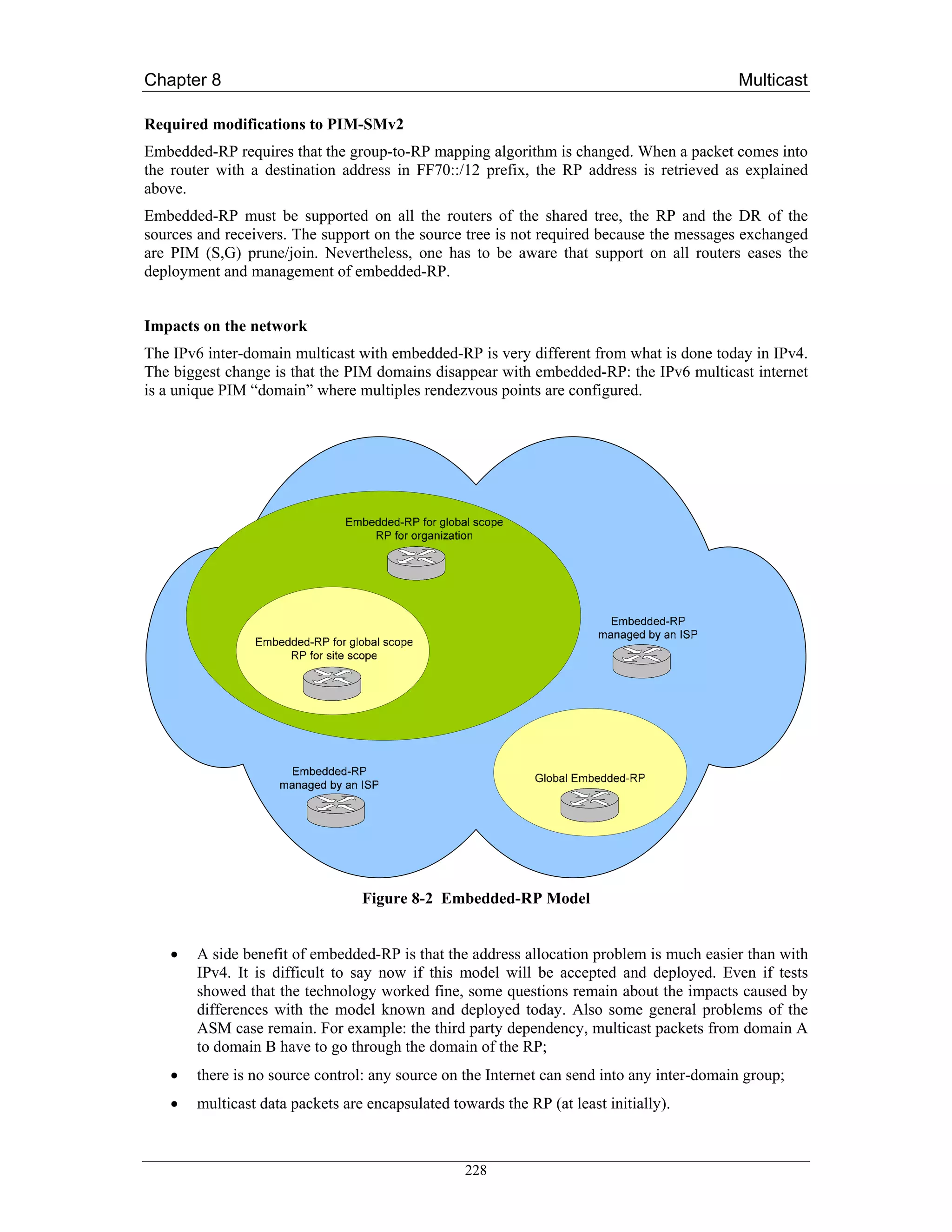
![Chapter 8 Multicast
8.4.3 Future Work
A general purpose inter-domain IPv6 multicast service can be deployed using two different
architectures: either ASM with embedded-RP, or SSM with a source discovery mechanism such as
SSMSDP. It is hard to tell if a solution or the other will be widely accepted and deployed.
Embedded-RP is quite new, and it’s not clear yet how the service best can be provided. One issue is
how to provide failover or possibly load balancing mechanisms. In order to do this, anycast-RP
mechanisms may be needed. For IPv6 MSDP is not available, but a possible solution is “Anycast-RP
using PIM” described in the Internet draft draft-ietf-pim-anycast-rp-02.txt [FC05].
Another issue is address assignment. Users should not need to know what the RP address is and
compute group addresses. Ideally applications or hosts should not care about RP addresses at all. But
there should be some way the user or application can be told what group address to use, or at least a
range to pick them from. Finally, another open issue is how to control usage of Embedded RPs. A
provider or organization configuring a router as an Embedded RP, may wish to use it only for sessions
for which at least some participants are customers or related to the organization.
There are also issues regarding SSM. One possible problem if SSM becomes widely used, is that
routers in the Internet may end up with a lot of multicast state, since state must be stored for every
single (S,G). This is a problem with current IPv4 ASM solutions as well. How to reduce this state
might be a topic for new research into multicast protocols. There are some protocols solving this in the
intra-domain case that cannot be used effectively inter-domain.
An issue with SSMSDP as specified and implemented today is that there is a single point of failure.
There is now work going on to have redundant controllers to achieve both reliability and load sharing.
A common issue for both Embedded-RP and SSMSDP compared to the current IPv4 inter-domain
multicast with MSDP, is that some entity must be responsible for providing the Embedded RP or the
SSMSDP controller. There might be long lasting sessions that have no natural owner. Maybe someone
from one organization starts a session and picks a group address using the organizations Embedded
RP, or runs a SSMSDP controller. It might be that that session lasts for a long time with multiple
participants, and that the creator wishes to leave. It may then be desired to use another RP or SSMSDP
controller for the session. This would however require either a new group G or a new channel (S,G) to
be chosen, and for the applications to migrate to that, ideally with no interruptions to the service.
Finally, to debug and manage inter-domain multicast, it is very useful to have support for mtrace.
mtrace is sort of multicast traceroute. There are a few implementations for IPv4, while we are only
aware of one for IPv6. There are attempts at specifying this in the IETF, but it is not clear whether it
will be standardized and how quickly.
8.5 MRIB - Multicast Routing Information Base
When the multicast topology is the same as the unicast one, multicast protocols can rely on the unicast
routing table. For example, PIM-SM in that case would rely on the unicast routing table to have
information about where to send Joins and Prunes. Also RPF checks would be made according to the
unicast routing table.
Unicast and multicast topologies can be different for several reasons (tunnels to bypass non-multicast
capable equipment, different peering policies for unicast and multicast, different VLAN’s for
management purposes etc.) In this case the unicast routing table cannot be used by any of the multicast
protocol. Multicast topology information needs to be stored in what is generally called the MRIB
(Multicast Routing Information Base). It is another instance of the routing table that is used for
multicast operations only.
The following figure illustrates the difference between the RIB and the MRIB. It shows 2 sites
interconnected through an ISP that is not IPv6 multicast capable. The 2 sites decided to establish a
tunnel to exchange IPv6 multicast traffic.
230](https://image.slidesharecdn.com/ipv6deployment-guide-110112200202-phpapp01/75/IPv6-Deployment-Guide-244-2048.jpg)
![Chapter 8 Multicast
Figure 8-3 MRIB and RIB
Each site router needs to be configured with a RIB and an MRIB as topologies differ for unicast and
multicast. On site B exit router, site A must be seen through the ISP for unicast while it must be seen
through the tunnel for multicast. Then a route should be configured in the RIB for site A prefix with
the ISP as next hop. Another route should be configured in the MRIB for site A prefix with the tunnel
interface as destination.
Routes can be inserted statically in the MRIB. A routing protocol is needed to exchange the multicast
routes between different domains, and sometimes also inside the same domain. MBGP [RFC2858] is a
widely used protocol for this.
8.5.1 Extensions to BGP (MBGP)
BGP is usually used for inter-domain unicast routing and by using MBGP (multiprotocol BGP) one
can exchange both unicast and multicast routes with BGP. MBGP adds additional attributes to BGP
for specifying whether information is IPv4 or IPv6, and whether it is unicast, for multicast RPF
checking or both. MBGP is sometimes, at least in multicast circles, called multicast BGP.
There is no difference between using MBGP for multicast in IPv4 and IPv6. Configuration should be
quite similar, and it is used in the same way. Note that MBGP is needed not only when doing ASM,
but also for SSM.
231](https://image.slidesharecdn.com/ipv6deployment-guide-110112200202-phpapp01/75/IPv6-Deployment-Guide-245-2048.jpg)
![Chapter 9 Security
DoS). Careful border filtering should prevent the particular addresses from being announced
or accessed outside the network’s administrative borders.
Other forms of finding potential targets
The attacker also can find out potential targets by simply setting up services as honeypot to
harvest addresses and after certain amount of time analyse the access logfiles of services to
find out potential targets. The hosts can be identifiable this way from the log files, however if
proper filtering is set up at the end-site the attacker will not get access to the potential targets.
Finally, a well known practice that is proven to be valuable under IPv4, filtering of unneeded services
at the network’s access points, can be equally useful under IPv6 for mitigating reconnaissance threats.
9.1.3 Unauthorised Access in IPv6 networks
Determining who has authorized access to a computer system is a policy decision. If this authorisation
is enforced in TCP/IP at Layer 3 or Layer 4 then it is usually implemented in firewalls. Policy
implementation in IPv6 at Layer 3 and Layer 4 is still implemented in firewalls with some design
considerations.
The filtering of packets whose source (or possible destination) address should never appear in Internet
routing tables (often called bogons) (e.g. non routable, non assigned etc.) is the minimal filtering that
firewalls should provide. In IPv4 it is easier to filter out (deny) packets originating from bogon routes,
while in IPv6 it is easier to allow legitimate packets as shown in table Table 9-1.
Table 9-1 Bogon Filtering Firewall Rules in IPv6
Rule Meaning
deny 2001:db8::/32 any Filter out documentation prefixes
allow 2001::/16 any Allow RIR allocated prefixes 1
allow 2003::/16 any Allow RIR allocated prefixes 2
allow 2002::/16 any Allow 6to4 relay prefix
allow 3ffe::/16 any Allow 6Bone prefixes - deprecated after 6th June 2006
deny any any Deny everything else
More detailed discussion about IPv6 firewalls can be found in section 9.2 “IPv6 Firewalls”.
Of course there is also the possibility of preventing unauthorised access to the IPv6 network below the
network layer. A port-based authentication mechanism such as 802.1x [8021x] is a sound way to
organise a secure network infrastructure. An 802.1x based infrastructure can integrate both wired and
wireless segments of an organisation’s network. For more information on using 802.1x with IPv6
wired and/or wireless networks please refer to [D4.2.2].
234](https://image.slidesharecdn.com/ipv6deployment-guide-110112200202-phpapp01/75/IPv6-Deployment-Guide-248-2048.jpg)
![Chapter 9 Security
9.1.4 Spoofing in IPv6 Networks
Most of the occurrences of various Denial of Service (DoS) attacks which have employed forged or
spoofed source addresses have proven to be a troublesome issue for Internet Service Providers and the
Internet community overall. RFC 2827 [RFC2827] recommends a simple, effective, and
straightforward method for using ingress traffic filtering to prohibit DoS attacks which use forged IP
addresses propagated from ‘behind’ an Internet Service Provider’s (ISP) aggregation point. The
method, called “ingress filtering” can only prevent spoofing of the source address. An important
benefit of implementing ingress filtering is that it enables the originator to be easily traced to its true
source, since the attacker would have to use a valid, and legitimately reachable, source address.
The ingress filtering is usually implemented at ISP edge routers with various methods, either via
firewall filters or by enforcing the uRPF (unicast reverse path forwarding) check. The behaviour of the
ingress filtering is the following:
# uRPF processing
IF (packet's source address is from network residing behind the interface
where the packet comes from) {
forward as appropriate
} ELSE IF (packet's source address is anything else) {
deny packet
}
A similar technique can be implemented by the end-user of an ISP to prevent sending packets that do
not belong to their network, usually called egress filtering.
These techniques can also be implemented in IPv6. IPv6 can make the ingress filtering easier, since
only one prefix should be configured for the ingress filter, due to the hierarchical aggregation of IPv6
addresses. Usually only one /48 has to be configured, if you cannot setup automatically the anti-
spoofing or uRPF (unicast Reverse Path Forwarding) check.
The egress filtering configuration is very similar to the ingress filtering configuration, the difference
being that it is configured at the user’s equipment.
We should note, that ingress and egress filtering might be more complex, albeit not impossible if
multihoming and multiple address prefixes are employed at the user site. In this case the multiple
address prefixes should be appropriately configured.
9.1.5 Subverting Host Initialisation in IPv6 Networks
In IPv4 environments it is rather easy to perform attacks against the ARP protocol, since hosts cannot
prove ownership of their MAC addresses. Therefore it is easy to hijack the default router on the
subnet. You can protect your network on a switch by enforcing a specific number of source MAC
address for all frames received on a specific port. This protection is available on some switches
(notably on modern Cisco Catalysts) as a feature called port security.
If we are using DHCP for initialising hosts, the attacker on the link can perform various attacks against
the DHCP server: operating a false DHCP server and delivering DHCP messages faster than the
original official DHCP server, exhausting resources of DHCP server by issuing large number of
requests, exhausting leased IP address space by requesting too many IP addresses etc. You can protect
235](https://image.slidesharecdn.com/ipv6deployment-guide-110112200202-phpapp01/75/IPv6-Deployment-Guide-249-2048.jpg)
![Chapter 9 Security
your system against such an attack by a combination of port security, DHCP snooping, and DHCP
message rate limiting. By using port security you can prevent rogue DHCP server operation and faking
different MAC addresses on a certain port. The DHCP snooping provides security by filtering
untrusted DHCP messages and by building and maintaining a DHCP snooping binding table. This
binding table can be used to prevent IP spoofing by only allowing IP addresses that are obtained
through DHCP snooping on a particular port.
The host neighbourship in IPv6 environments also can be attacked in a similar way to ARP. Possible
attacking techniques could be: sending false Neighbour Advertisement messages, performing Denial
of Service against the Duplicate Address Detection procedure, or sending fake Router Advertisements
as described in RFC 3756 [RFC3756]. To mitigate attacks against the Neighbour Discovery procedure
you can deploy Secure Neighbour Discovery (SEND) [RFC3971]. More detailed discussion about
Secure Neighbour Discovery can be found in section 9.3.
9.1.6 Broadcast Amplification in IPv6 Networks
There have been several broadcast amplification attacks against IPv4 network infrastructures. The
most famous was the smurf attack where the attacker sent out the packet with following content:
Table 9-2 Structure of the Smurf Attack Packets
Spoofed address of Subnet broadcast address ICMP echo
attack target of amplifier network
There were two problems that allowed the smurf attack to work:
1. Ingress filtering was not implemented which allowed spoofing the source address field of the
attack packet.
2. The host operating systems answered to a message destined to a broadcast address.
Such a problem cannot be foreseen in IPv6 environment for various reasons:
There is no broadcast address in IPv6 environment
This would stop any type of amplification/smurf attacks that send ICMP packets to the
broadcast address. However global multicast addresses for special groups of devices, e.g. link-
local addresses, site-local addresses, all site-local routers, etc. are available to reach groups of
devices.
The IPv6 specification does not allow answering to multicast destinations
IPv6 specifications forbid the generation of ICMPv6 packets in response to messages to global
multicast addresses except in two case as described in RFC 1885 [RFC1885]:
1. The Packet Too Big Message - to allow Path MTU discovery to work for IPv6
multicast
2. The Parameter Problem Message, Code 2 - reporting an unrecognized IPv6 option that
has the Option Type highest-order two its set to 10.
236](https://image.slidesharecdn.com/ipv6deployment-guide-110112200202-phpapp01/75/IPv6-Deployment-Guide-250-2048.jpg)
![Chapter 9 Security
9.1.7 Attacks Against the IPv6 routing Infrastructure
The primary purpose of IP routing attacks are to disrupt/corrupt router peering or routing information
in order to cause denial of service attack or provide help to other type of attacks like DNS cache
poisoning etc.
In an IPv6 environment the operators of the network can face similar attacks against the routing
infrastructure. However in an IPv6 environment the network designers should be aware of certain
idiosyncrasies of IPv6 routing.
In the cases of BGP, IS-IS and EIGRP the security algorithms of the routing protocol remains the
same: keyed MD5 digest. So in these cases the same protection for the routing protocol should be
used.
By contrast, in the case of OSPFv3 [RFC2740] and RIPng [RFC2080] the routing protocol has been
adapted to IPv6 and relies on the IPSec protocol. So if you are using OSPFv3 or RIPng for routing you
should also configure IPSec to protect these routing protocols.
The other types of attacks against the routing infrastructure as mentioned are very similar to IPv4
routing infrastructure attacks, therefore similar countermeasures should be implemented: e.g.
infrastructure protection, limiting access to the router, SSH authentication etc.
9.1.8 Capturing Data in Transit in IPv6 Environments
Capturing unprotected data in IPv6 networking environment very much like sniffing in IPv4
environment. Ethereal, a tool already widely used by system/network administrators in various
platforms and networks is such an example. Other similar tools sporting IPv6 capabilities and not
limited to “passive sniffing” of the physical layer, are soon expected to appear, if they do not exist
already. The conclusion is that this type of attack presents similar to IPv4 and real threat for services
over IPv6.
However, the mandatory support of IPSec in IPv6 environment might help resolving the problem since
the infrastructure to protect any kind of communication (e.g. SQL database queries) is built into the
systems, and can be protected against sniffing
9.1.9 Application Layer Attacks in IPv6 Environments
These days the most common attacks against computer systems are targeted at the application layer.
Often these attacks gain access to system resources by exploiting buffer overflows in the applications
or by gaining elevated privileges by executing code with inappropriate checking.
These types of attacks are not bound to any underlying network protocol, so we can not expect any
changes if we are deploying IPv6. The operators of the services, must be aware of the problems, and
update their systems to prevent such an attacks to happen.
9.1.10 Man-in-the-middle Attacks in IPv6 Environments
Without application of IPSec, any attacks utilizing Man-in-the-middle techniques will have the same
likelihood in IPv6 as in IPv4.
If we keep in mind that IPSec is strongly linked to IPv6, its usage alone would be enough to avoid any
problems regarding connection hijacking attempts. Unfortunately, the dominant practice we see today
237](https://image.slidesharecdn.com/ipv6deployment-guide-110112200202-phpapp01/75/IPv6-Deployment-Guide-251-2048.jpg)
![Chapter 9 Security
9.2 IPv6 Firewalls
In the 1990s, firewalls became the building block of each IP network. The recent growth of IPv6 usage
has necessitated analysing whether the new protocol can provide enough security without the use of
IPSec. This analysis is also important since the application of IPSec on the Internet is relatively scarce
and probably will be limited due to deployment difficulties of the public key infrastructure, and in
spite the fact that IPSec itself provides a good, modular framework. This section tries to analyse what
is available and what is missing for effective IPv6 firewalling.
The Internet firewall is a system that implements and enforces the security policy between two
networks: usually protects an internal private network (Intranet) from external Internet threats.
Sometime firewalls are also implemented with more than two network interfaces, where the third,
fourth interfaces are used for special purposes like DMZs (DeMilitarised Zones), etc.
The firewalls usually can be operated at different levels in the networking hierarchy:
IP level Packet filtering firewalls
Transport level Circuit oriented firewalls
Application level Application level proxies. There is a higher level of support in
the application level proxies, e.g. transparent proxies and
modularisation
The most important principle of firewalls, however, is function in helping to enforce the security
policy (administrative rules) that will protect certain assets. The majority of modern firewalls employ
a mix of protective methods at different levels.
In IPv6 the levels are not changed, therefore we can expect that firewalls should support IPv6 at any
level. A good firewall implementation should be IP version agnostic at transport or application levels.
We will focus our discussion to packet filtering firewalls for two reasons.
1. These types of firewalls are the basic elements for the more advanced firewalls. They have
become necessary components due to the very large number of existing protocols on the
Internet (e.g. a wide variety of H.323 related standards, instant messaging protocols, even
FTP) that prevents the operation of proxy services for every one of them
2. Currently there are only very few application level firewalling solutions available on the
market that offer IPv6 capabilities.
9.2.1 Location of the Firewalls
Traditionally the firewalls are installed next to the interconnecting device (usually routers) in order to
choke the unwanted traffic as close to the originating point as possible. Nowadays the firewalls
(usually more then one at each network) are installed in front of the device or network, which must be
protected. What are the implications of enabling IPv6 on these firewalls [Moh01], [Moh04].
• The firewalls should support Neighbour Discovery ICMPv6 message processing – This issue
is rarely discussed with IPv4 firewalls: The IPv4 firewalls must support ARP protocol. The
Neighbour Discovery Protocol (RFC 2461) is an extension of ARP for IPv6, therefore IPv6
firewalls must support Neighbor Discovery Protocol filtering "out of the box".
• The IPv6 firewalls should not filter out packets with proper fragmentation header. A common
practice in IPv4 firewalls, to guard against the tear-drop attack or other cases of heavily
239](https://image.slidesharecdn.com/ipv6deployment-guide-110112200202-phpapp01/75/IPv6-Deployment-Guide-253-2048.jpg)
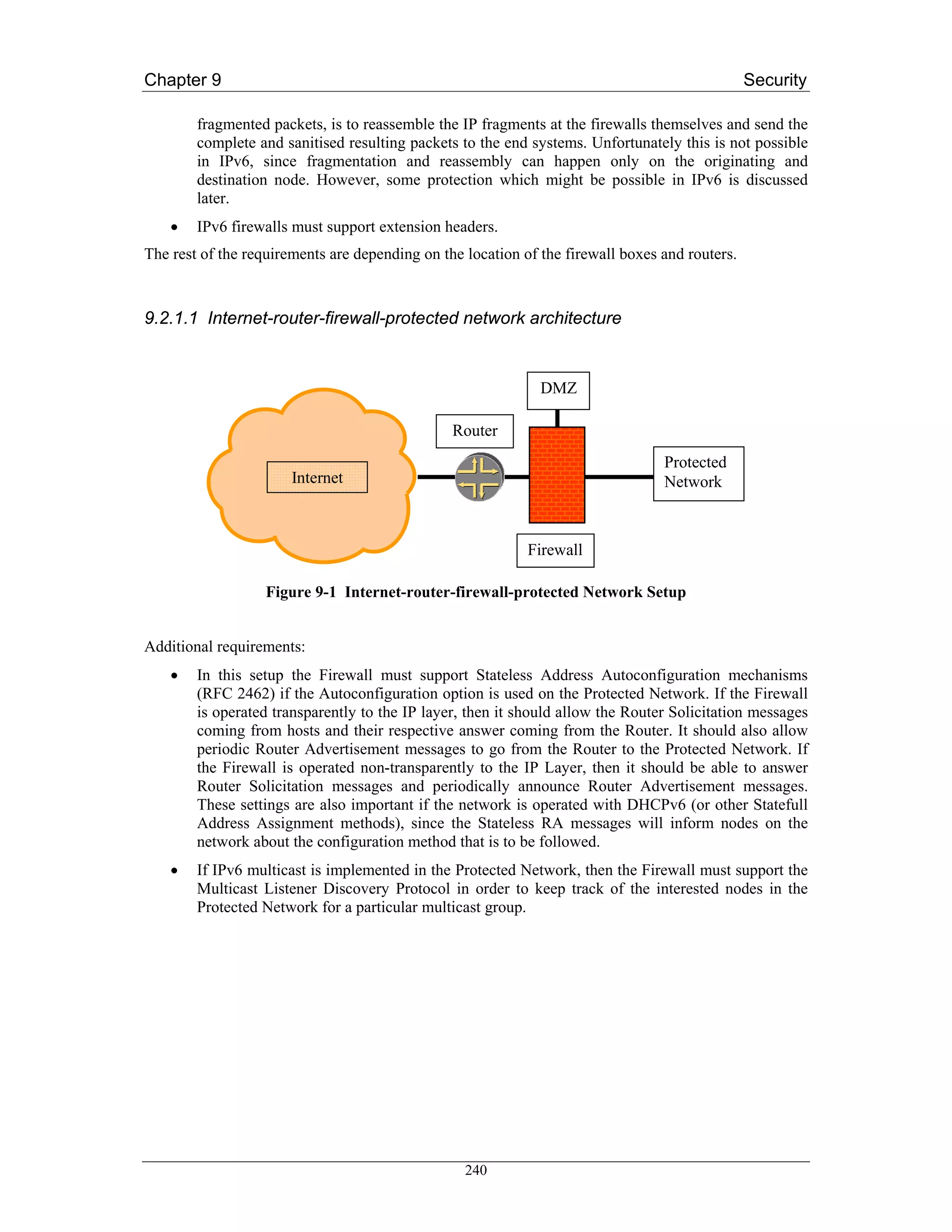
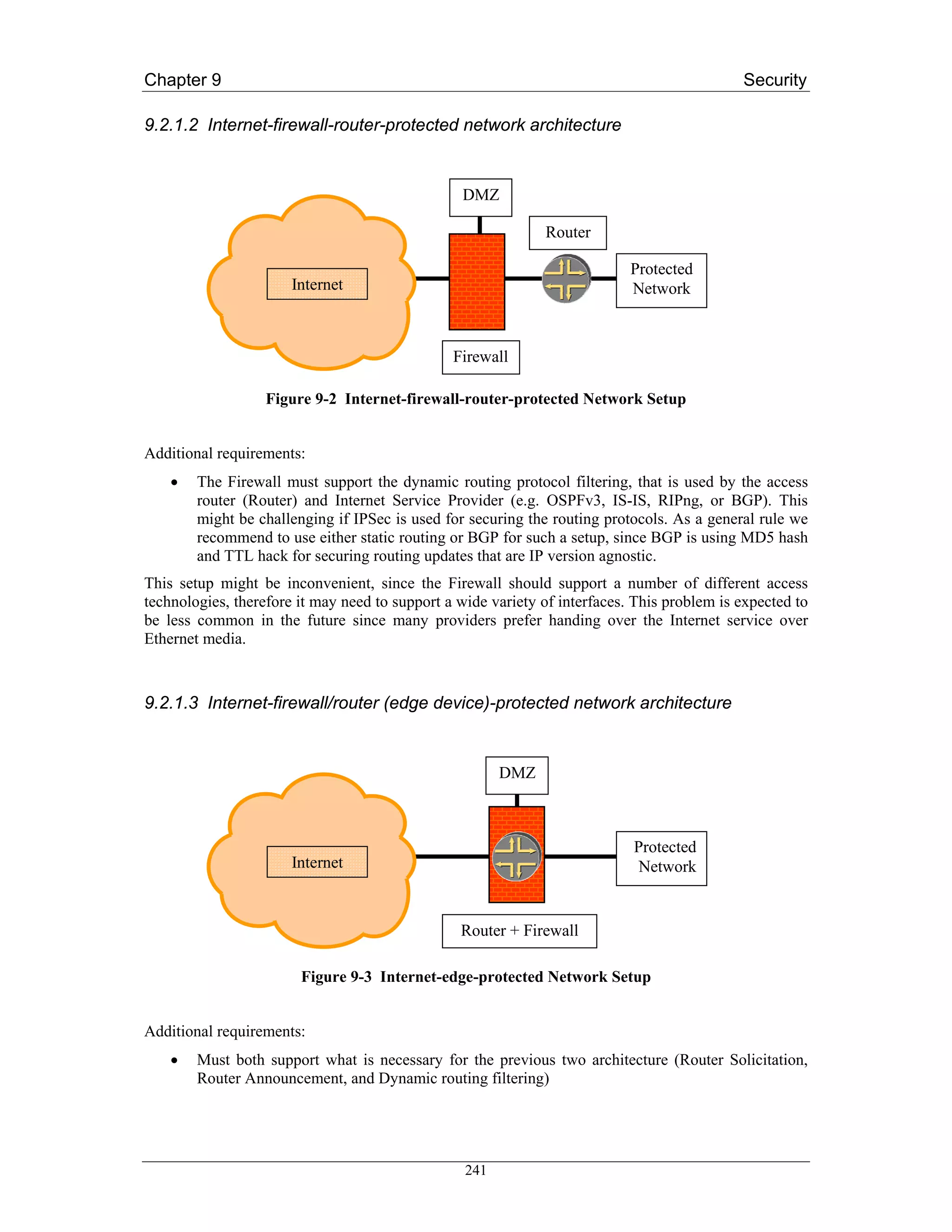
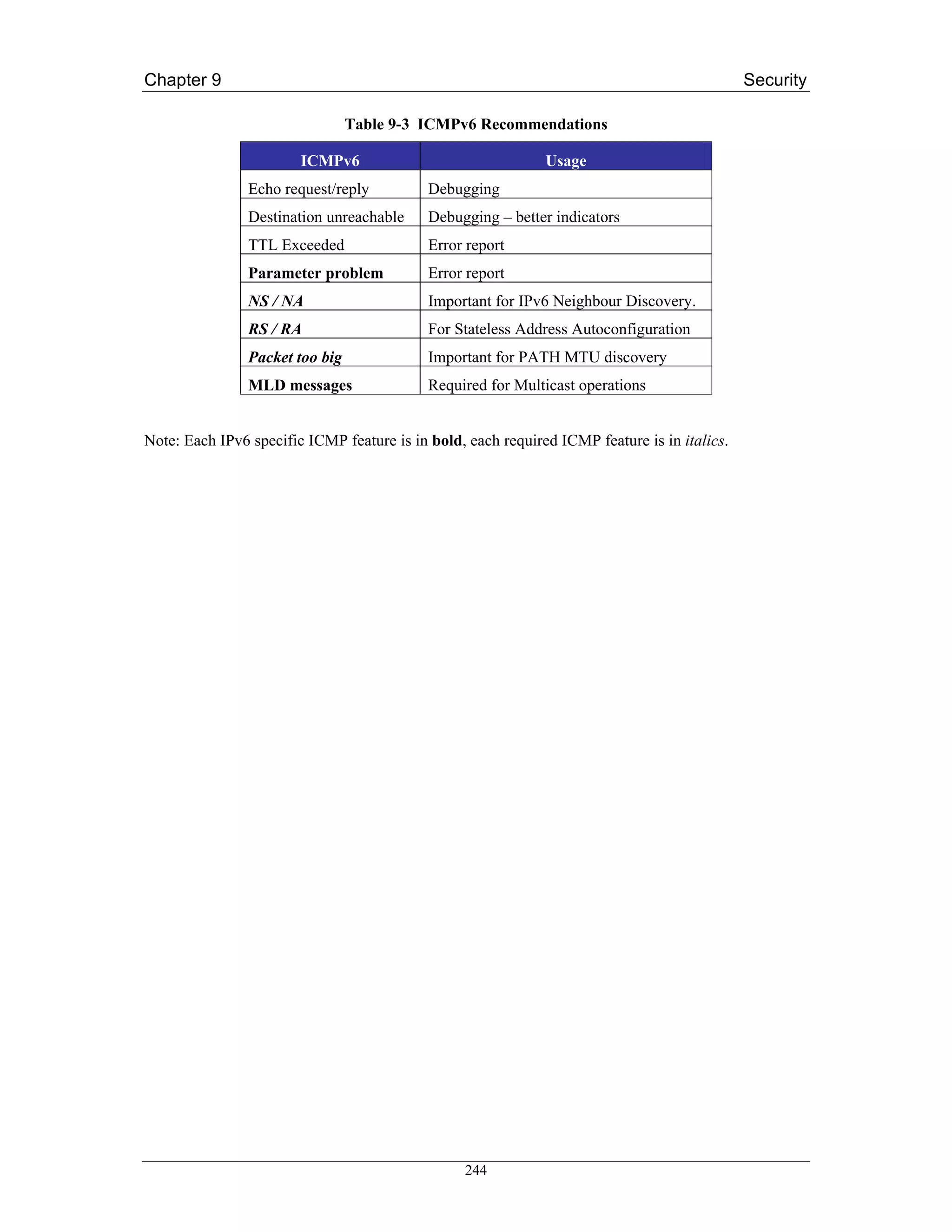
![Chapter 9 Security
9.3 Securing Autoconfiguration
The current operational practice in an IPv4 environment is to somehow keep track of which machine is
using which IPv4 address at a certain point in time either by statically allocating IPv4 addresses or by
using DHCP and keeping lease logs. It is also very common to identify machines in the enterprise
network management systems by their MAC addresses. It is thus crucial for the secure and efficient
operation of IPv4 networks to log the IP address, MAC address and L2 port combinations. There are
also some tools, implemented in L2 switches, to prevent DHCP abuse and ARP poisoning called
DHCP snooping and ARP inspection respectively. Let’s see what is possible in IPv6, and what
countermeasures are possible to prevent abuse. There are different possible ways to assign IPv6
addresses as described in the following sections.
9.3.1 Using Stateless Address Autoconfiguration
In this method the globally aggregatable unicast address is derived from the prefix advertised by the
routers and the IEEE EUI-64 identifier (RFC 2462). Since the EUI-64 identifier is generated from the
MAC address if it was available, then mapping the IP address to a MAC address is very easy to do.
Only MAC addresses and L2 port mapping should be implemented. Enforcing the usage of the EUI-64
identifiers as part of IPv6 addresses could be easily enforced by firewalls. Some firewalls already
allow checks MAC address and EUI-64 address consistency of the outgoing packets. This way the
accountability of the outgoing communications can be easily provided. However, you should
configure carefully your firewall rules if you also use statically assigned addresses.
9.3.2 Using Privacy Extensions for Stateless Address
Autoconfiguration
Addresses of this type were developed due to concerns that the same Interface identifier could be used
anytime in multiple communication contexts. In this case it becomes possible for that identifier to be
used to correlate seemingly unrelated activity. But privacy extended addresses are considered harmful
[DS04] for several reasons:
• They complicate debugging, troubleshooting
• They require frequent updates on the reverse DNS entries
• They allow easier in-prefix address spoofing
• In the current form temporary and forged addresses cannot be distinguished
• They do not improve the prefix privacy
Therefore we do not recommend using privacy extended address as defined in RFC 3041. The updated
standard addresses [NDK05] solve some of the problems above. There is also a new IPv6 feature
called Cryptographically Generated Addresses (CGA) [RFC3972], which generates a random interface
identifier based on the public key of the node. The goal of CGA is to prove ownership of an address
and to prevent spoofing and stealing of existing IPv6 addresses.
To prevent using RFC 3041 type of addresses you can use the filtering technique described in the
previous section.
9.3.3 Using DHCPv6
DHCPv6 is the "statefull address autoconfiguration protocol" and the "statefull autoconfiguration
protocol" referred to in "IPv6 Stateless Address Autoconfiguration" (RFC2461).
DHCP can provide a device with addresses assigned by a DHCP server and other configuration
information, which are carried in options.
245](https://image.slidesharecdn.com/ipv6deployment-guide-110112200202-phpapp01/75/IPv6-Deployment-Guide-259-2048.jpg)
![Chapter 9 Security
DHCPv6 (RFC 3315) servers use DUIDs (DHCP Unique Identifier) to identify clients for the selection
of configuration parameters and in association with IA clients (Identity association - a collection of
addresses assigned to a client). DHCP clients use DUIDs to identify a server in messages where a
server needs to be identified.
The DUID can be generated from several different sources:
1. DUID Based on Link-layer Address Plus Time (DUID-LLT)
2. DUID Assigned by Vendor Based on Enterprise Number (DUID-EN)
3. DUID Based on Link-layer Address (DUID-LL)
In the case of DUID-LLT and DUID-LL, the association between the IPv6 address and Link-layer
address (usually MAC) still exist in the state information of the DHCPv6 server, so accountability is
still possible. In the case of DUID-EN it is the responsibility of the administrator to build such a
pairing.
If the addresses are assigned from a well identifiable sub-range in /64 the firewalls can ensure that
only hosts using DHCPv6 for address configuration can connect outside of the protected network.
Unfortunately, currently there is no similar technique available on the market that will allow only real
DHCPv6 servers to assign addresses to the requester hosts.
9.3.4 Static Address Assignment
The static address assignment is very similar to IPv4 static assignment therefore similar pitfalls might
possible if it is used.
9.3.5 Prevention techniques
A technique similar to the one that prevents ARP cache poisoning (in IPv6 ND cache poisoning) is
possible but it requires DHCPv6 snooping. Firewalls can enforce the DHCPv6 usage and make the
DHCPv6 address assignment the default method, thus making DHCPv6 snooping easier to implement.
Currently no DHCPv6 snooping support is available for any networking device.
IPv6 can provide an option to prevent ND cache poisoning in the case of stateless autoconfiguration
via snooping the Neighbour Solicitation and Neighbour Advertisement messages: Neighbour
Solicitation messages contain an informational pair [source_IPv6, source_MAC] that can be stored,
while Neighbour Advertisement messages contain two informational pairs: [source_IPv6,
source_MAC] and [destination_IPv6, destination_MAC] which can be also stored. Any case of a
mismatch can be diagnosed from the previously stored ND entry and the switch can disable the
abusing port. A "light version" of the above protocol can be implemented in Firewalls: detect and
report ND entry changes i.e. different IP address with same MAC address etc.
9.3.6 Fake router advertisements
Router Advertisements are one of the well-known differences between IPv6 and IPv4. IPv4’s common
method to supply an address for a (default) gateway is either through DHCP or static configuration. In
IPv6, geographic network routers that are connected to the same link may use the Neighbour
Discovery protocol for a variety of purposes, such as discover each other’s presence, determine each
other’s link-layer addresses, learn parameter values necessary for communicating and exchange
information about prefixes they know about. However, such mechanism has a cost in terms of risk
from the security viewpoint. The potential range of attacks that one could make taking the place of a
network segment’s default gateway is considerable.
Routers consider the information carried in router advertisements sent by other on-link routers as
authoritative, even though such information is not cryptographically secured (e.g., digitally signed or
key-MACed or encrypted). Therefore, routers update the affected communication parameters
accordingly, without any verification. In the absence of any verification of the received information,
246](https://image.slidesharecdn.com/ipv6deployment-guide-110112200202-phpapp01/75/IPv6-Deployment-Guide-260-2048.jpg)
![Chapter 9 Security
9.4 IPv4-IPv6 Co-existence Specific Issues
A lot of work has been undertaken inside the 6NET project to investigate and report on the existing
IPv6 mechanisms. This section looks closely on the potential risks deploying the mechanisms and
reports on the security issues raised by the use of them with the overall aim to create awareness to the
people that manage the migration to an IPv6 network.
The next sections reviews general issues arising by the use of tunnels especially automatic tunnels and
operational issues of NAT-PT
Generally, any form of tunnelling poses a security threat to a network. If set up properly tunnels can
effectively circumvent and undermine any security features present to guard the network like access
control lists and firewalls. In a way they drill a hole through them since these security measures only
“see” the outer layer of the packets, which might be well within the permitted parameters but have
nothing at all to do with the contents/protocol/traffic inside. So if this traffic reaches a tunnel end-point
inside the guarded network it is decapsulated and from there can potentially be very harmful since
within a network itself, defence levels are usually much lower. Tunnels used for IPv6 deployment are
no exception.
During the migration from IPv4 to IPv6 three different kinds of tunnels may be used: IPv6-in-IPv4,
IP(v4)-in-IPv6 or other layer tunnels. In terms of general management of tunnels, RFC 4087
[RFC4087] describes managed objects used for managing tunnels of any type over IPv4 and IPv6
networks.
9.4.1 General Management Issues with Tunnels
Often the tunnel MTU is not specifically configured on the end-points when a tunnel is set up. The
system then chooses a default MTU. In Cisco’s IOS, for example, the default MTU will be derived
from the interface MTZ of the interface towards the other end-point (by subtracting the encapsulation
overhead). Even if this happens to result in the same MTU at both end-points at the time the tunnel is
set up, the MTUs may diverge later (e.g. if one of the end-points starts to support jumbo frames on the
egress interface, or routing changes cause the egress interface to move to one with a different MTU).
The resulting situation is a logical IP(v6) subnet where not all interfaces have the same MTU. This
violates a fundamental assumption in IP networking and causes connectivity problems.
However, the symptoms are such that this situation is often hard to diagnose. In the direction from the
end-point with the smaller MTU towards the receiver with a larger MTU interface, no problems will
show but the other way around packets with larger size than the receiver’s MTU will usually be
ignored and counted as errors at the receiver. Typical tests with ping or traceroute will not show any
problems because these tools use small packets. Protocols like BGP may work over the tunnel most of
the time but may come to the point where the side with larger MTU must send a large amount of data
and uses larger packets than the other side can take.
Unfortunately some devices (seen on Cisco routers under IOS) ignore attempts to configure a 1480-
byte MTU on a tunnel towards a 1500-byte MTU interface, because this is already the default. In these
cases we recommend to fix the devices so that they still accept the manually configures MTU. This
will guard against problems arising when the “default MTU” changes.
MTU incompatibilities are detected by some routing protocols such as OSPFv3, which is very useful
for debugging. However, such protocols usually are not used over inter-domain tunnels, where
problems are most likely to occur. From this point of view it would seem useful if BGP-4 had an
option to advertise link MTU in the single-hop case. Alternatively, MTU validation could be made
part of a link liveliness detection protocol such as BFD (bidirectional forwarding detection).
248](https://image.slidesharecdn.com/ipv6deployment-guide-110112200202-phpapp01/75/IPv6-Deployment-Guide-262-2048.jpg)
![Chapter 9 Security
Note that path MTU discovery ([RFC1191, [MHL05]) would make it possible for the end-points to
discover the largest MTU that can be supported by the underlying network without fragmentation, but
this doesn’t solve the inconsistent MTU problem, because there is no guarantee that the path MTUs in
both directions end up being the same. Also it isn’t always implemented for tunnel interfaces (see
IPv6-in-IPv4 tunnels).
9.4.2 IPv6-in-IPv4 tunnels
This category of tunnels covers the most basic and well-known transition mechanisms Manually
Configured Tunnels, 6to4 and ISATAP. We will cover any specific operational, management and
security issues of these mechanisms below. All of these mechanisms however have quite a few issues
in common since they all encapsulate IPv6 packets in IPv4 packets.
9.4.2.1 General security issues with IPv6-in-IPv4 tunnels
Security Issues with IPv6-in-IPv4 tunnels in general lie mainly in the above mentioned problem of
these tunnels circumventing and subverting security measures present for IPv4, specifically normal
(IPv4-based/IPv6 unaware) firewalls on which IPv4-encapsulated IPv6 traffic only registers as IP
protocol type 41 (IPv6). If one wants to use IPv6-in-IPv4 tunnels, this protocol type has to be
permitted in the firewall’s rules and in some cases also protocol type 58 (ICMPv6). This will
effectively open a hole in the carefully configured and maintained security of the site as the traffic is
let through without further inspection. This IPv6 traffic can be anything and, if the tunnel end-point
also acts as an IPv6 router and forwards IPv6 traffic inside the site’s IPv6 network, upon reaching the
tunnel end-point inside the site could go anywhere undetected after decapsulation (though the potential
damage is in most cases limited to the broadcast domains that the tunnel end-point resides in).
An example:
A site filters all incoming and outgoing (IPv4) http traffic unless it originates from or goes to a
specific host (proxy). This protects otherwise unprotected web servers inside the network (i.e.
web interfaces for configuration of network components) against attacks from the outside. The
other way around this could (if the proxy were properly configured) prevent access to certain
websites from inside the site. If the site now uses any IPv6-in-IPv4 tunnel mechanism to get
(global) IPv6-connectivity, this tunnel most likely needs to pass the firewall to an end-point on
the inside, which then becomes the site’s IPv6 border router. Any (IPv6) http traffic may then
travel anywhere from and to IPv6 nodes in the network, which again leaves IPv6 enabled (and
connected) network nodes with IPv6 enabled web interfaces vulnerable to attacks from the
outside, if they are executed via IPv6.
The best way to remedy this problem is to install an IPv6 capable firewall on the tunnel end-point that
examines and properly filters the incoming IPv6 traffic after it has been decapsulated from the IPv4
wrapping. This firewall could mirror any rules present for IPv4 at the site’s border for IPv6. This is the
only way to let only specific IPv6 traffic in and out of the site through the tunnel.
If one only wants to filter specific traffic, one could theoretically employ bitwise filtering and look for
specific bit patterns in the payload of the packets. This might make it possible to filter on at least IPv6
source and destination addresses; but this is very tiresome, prone to mistakes and not at all scalable.
We do not assume that anyone would try to do this but want to state specifically that we recommended
not using this method nor any other kind of packet filtering that will not work on the decapsulated
IPv6 packets.
Even when using a proper IPv6 firewall on the decapsulated packets, one must be careful when setting
up a tunnel because any host could potentially spoof the other end-point’s IPv4 address and send IPv6-
in-IPv4 encapsulated packets. The local tunnel end-point will not know that the source of these
packets is not the real remote tunnel end-point and decapsulate the IPv6 traffic which can then (if not
249](https://image.slidesharecdn.com/ipv6deployment-guide-110112200202-phpapp01/75/IPv6-Deployment-Guide-263-2048.jpg)
![Chapter 9 Security
decapsulation and encapsulation. The only problem here is, that an attacker can more easily
cover his tracks. The unidirectional source address spoofing of course also exists without 6to4
but becomes harder because the attacker needs to know a valid (existing) IPv6 address. This is
a lot easier with 6to4 present because here the attacker can just take any non-6to4 address.
Attacks like these two can also only be remedied by employing sufficient filters. For example all IPv6
nodes inside the site can be guarded from attacks, if the 6to4 pseudo interface does not accept traffic
from the IPv6 prefix(es) used inside the site. This also means that the site’s own 6to4 prefix should be
filtered on input.
Additional security issues with 6to4 relays are due to the fact that 6to4 relays by nature have a native
IPv6 connection in addition to IPv4 and relay rather freely between the two. Native IPv6 nodes
anywhere can use the relay as a means to obscure their identity when attacking (possibly even IPv4
nodes). Attackers from IPv6 can attack IPv4 hosts with tunnelled packets sending spoofed 6to4
packets via a relay to the IPv4 hosts. The relay can obscure identity, if it relays any packets whilst not
checking if the 6to4 address actually matches the IPv4 host the packet comes from. Note that for
relays it is assumed that it is at least configured in a way as to not relay between different 6to4
addresses (except of course from or to other known 6to4 relays), thereby facilitating IPv4 to IPv4
attacks.
1. A 6to4 relay can be used for locally directed (IPv4) broadcast attacks. For example if the relay
has an interface with address w.x.y.z/24 an attacker could send packets with a 6to4 address
that translates into the address w.x.y.255. This is even possible to remote locations if “no ip
directed broadcast” is not configured.
This problem however is easily remedied by another entry in the access list, which prevents
packets with destination similar to the above 6to4 address from getting in.
2. The issue mentioned above is actually only a special case of the general problem of 6to4
relays becoming a part of DoS attacks against IPv4 nodes which might be totally unaware of
6to4 but get hit by encapsulated packets nevertheless. If the attack further is executed with a
spoofed source address (which is easily possible as stated above) the source of the attacks
cannot be traced. A 6to4 relay can also be used for address spoofing and therefore
anonymization of attacks coming from native IPv6 hosts
Generally, a 6to4 relay can be reasonably well protected if the validity of source or destination 6to4
addresses is always checked. That is, it should be checked if the enclosed IPv4 address is a valid
global unicast IPv4 address. It could even be restricted to only accepting and forwarding 6to4
encapsulated traffic where the 6to4 destination or source address matches the actual IPv4 address the
packets come in from or go to. As with the general rule about no forwarding between 6to4 addresses
however, exceptions must be made for traffic coming from or going to known other 6to4 relays.
For more information about security considerations with 6to4 please refer to [RFC3964].
9.4.3.2 Management issues with 6to4
However well protected a 6to4 relay may be, the traffic going through should always be monitored,
especially if the relay is configured with the well-known IPv4 anycast address for public 6to4 relays.
Other than monitoring no particular management is required for 6to4 since it was specifically designed
for ease of use and low maintenance.
252](https://image.slidesharecdn.com/ipv6deployment-guide-110112200202-phpapp01/75/IPv6-Deployment-Guide-266-2048.jpg)
![Chapter 9 Security
the TEP as an IPv4 relay or to access internal IPv4 resources. So, in the VPN scenario, the mapping in
the TEP must be managed by the DSTM server which authenticates the DSTM host and its IPv6
address. This is an important requirement that avoids the use of IPv4 resources by non authorized
nodes.
Finally, for IPv4 communications on DSTM nodes, once the node has an IPv4 address, IPSec can be
used since DSTM does not break secure end-to-end communications at any point. The tunnel between
the DSTM host and the TEP can be ciphered, but it is our view that this is more of an IPv6 feature
(like the use of IPv6 mobility) than a DSTM feature
9.4.10 NAT-PT/NAPT-PT
As noted in RFC 2766 [RFC2766], NAT-PT and end-to-end security do not work together. When an
IPv6-only node (X) initiates communication to IPv4-only node Y, the packets from X have certain
IPv6 source and destination addresses which are both used in IPSec (AH or ESP) and
TCP/UDP/ICMP checksum computations. Since NAT-PT translates the IPv6 address of X into an
IPv4 address that has no relationship to X’s IPv6 address, there is no way for recipient Y to determine
X’s IPv6 address and in that way verify the checksums.
9.4.10.1 Prefix Assignment
RFC2766 does not explain how the IPv6 nodes learn about the prefix that is used to route packets to
the NAT-PT box. If the prefix is pre-configured in IPv6 nodes, the IPv6 node would prepend the
preconfigured prefix to the address of any IPv4-only node with which it wants to initiate
communications. However, with a prefix, there might be a reachability problem if the NAT-PT box
were to shut down unexpectedly. If an attacker would somehow be able to give the IPv6 node a fake
prefix, the attacker would be able to steal all of the node’s outbound packets to IPv4 nodes.
Even though this is not specified in RFC 2766, DNS servers and DNS-ALGs should be used for
outgoing connections to return the prefix information to the IPv6 node as a means to avoid the
problem of a statically preconfigured prefix. When an IPv6-only node wishes to initiate
communications with an IPv4-only node, its resolver would send an AAAA query. This query can be
passed through the DNS-ALG which itself looks for an A record. In this case the DNS-ALG can
prepend the appropriate prefix for NAT-PT itself and thus return a full AAAA record to the IPv6-only
node.
9.4.10.2 Security Issues Arising when Using a DNS-ALG
A DNS-ALG is required when IPv4-only nodes should be allowed to initiate communication within a
NAT-PT scenario. Since the DNS-ALG will translate simple “A record” requests into “AAAA record”
requests and vice versa DNSSEC will not work in this case. However, as pointed out in draft-durand-
v6ops-natpt-dns-alg-issues [Dur03], if the host sets the “AD is secure” bit in the DNS header, it is
possible for the local DNS server to verify signatures. Also another option to increase security is for
the DNS-ALG to verify the received records, translate them and sign the translated records anew. A
third option would be if the host had an IPSec security association with the DNS-ALG to protect DNS
records.
In case the DNS-ALG also monitors the state of a number of NAT-PT boxes and use only the prefixes
of those that are running. The method by which a DNS-ALG determines the state and validity of a
NAT-PT box must of course also be secure. The DNS-ALG and each NAT-PT box should be
configured with a pairwise unique key that will be used for integrity-protected communications. Note
that messages from a DNS-ALG are not integrity-protected and can therefore be modified. To prevent
such a modification, a DNS-ALG can sign its packets. The DNS-ALG’s public key can be made
258](https://image.slidesharecdn.com/ipv6deployment-guide-110112200202-phpapp01/75/IPv6-Deployment-Guide-272-2048.jpg)
![Chapter 9 Security
available like that of any other DNS server (see RFC 2535 [RFC2535]) or presented form of a
certificate that has a well known root CA. A shared key technique may not be as practical.
9.4.10.3 Source address spoofing attack
There are two cases in which an attacker will use NAT-PT resources, one where the attacker is in the
same stub domain as the NAT-PT box and the second where the attacker is outside the NAT-PT stub
domain.
Suppose that an attacker is in the same stub domain as the NAT-PT box and sends a packet destined
for an IPv4-only node to the other side of the NAT-PT-gateway, forging its source address to be an
address that topologically would be located inside the stub domain. If the attacker sends many such
packets, each with a different source address, then the pool of IPv4 addresses may quickly get used up,
resulting in a DoS attack (or rather Address depletion attack). A possible solution to this attack as
well as to similar attacks like resource exhaustion or a multicast attack is to perform ingress filtering
on the NAT-PT box (which is the border router). This would prevent an attacking node in its stub
domain from forging its source address and thus from performing a reflection attack on other nodes in
the same stub domain. The NAT-PT box should also drop packets whose IPv6 source address is a
multicast address. Address Depletion attacks can be prevented by employing NAT-PT in a way that it
translates the TCP/UDP ports of IPv6 nodes into the corresponding TCP/UDP ports of the IPv4
nodes/addresses. However, sessions initiated by IPv4 nodes are restricted to one service per server. Of
course IPSec might be used to further increase security.
Suppose now that an attacker outside the NAT-PT domain sends a packet destined to an IPv6-only
node inside the NAT-PT domain and forges its (IPv4) source address to be an address from the IPv4
address pool used for NAT-PT. The same attacks are then possible as in the scenario above. Again
filtering can be used to prevent this. The NAT-PT gateway should drop all packets whose IPv4 source
address is a broadcast/multicast address. It should also filter out packets from outside that claim to
have a source address from inside the NAT-PT domain.
9.4.11 Bump in the API (BIA)
Security issues with BIA mostly correspond to those of NAT-PT. The only difference is that with BIA
address translation occurs in the API and not the network layer. The advantage here is that, since the
mechanism uses the API translator at the socket API level, hosts can utilise the security of the
underlying network layer (e.g. IPSec) when they communicate via BIA with IPv6 hosts using IPv4
applications.
Another security issue NAT-PT and BIA have in common stems from the use of address pooling,
which may open a denial of service attack vulnerability. One should employ the same sort of
protection techniques as mentioned fore NAT-PT in this regard.
Note that since there is no DNS ALG necessary with BIA as it is with NAT-PT, there is no
interference with DNSSEC when using this transition mechanism.
259](https://image.slidesharecdn.com/ipv6deployment-guide-110112200202-phpapp01/75/IPv6-Deployment-Guide-273-2048.jpg)
![Chapter 10 Mobility
Chapter 10
Mobility
The Mobile IPv6 (MIPv6) protocol [RFC3775] is a proposed standard by the IETF to provide
transparent host mobility within IPv6. The protocol enables a Mobile Node to move from one network
to another without the need to change its IPv6 address. A Mobile Node is always addressable by its
home address, which is the IPv6 address that is assigned to the node within its home network. When a
Mobile Node is away from its home network, packets can still be routed to it using the node’s home
address. In this way, the movement of a node between networks is completely invisible to transport
and other higher layer protocols.
Mobile Nodes participating in the MIPv6 protocol each have a persistent home address, which can be
used to address the Mobile Node irrespective of its current point of attachment to the IPv6 network.
The IPv6 network which matches the home address’ prefix is known as the home network. Mobile
Nodes also adopt a Home Agent - an IPv6 capable router directly connected to the home network. This
process may either be static, or dynamic, via the MIPv6 Home Agent discovery mechanism. The
Home Agent is responsible for the interception and forwarding of IPv6 packets to the Mobile Node
which are incorrectly routed to the home network while the Mobile Node is away from home.
When a Mobile Node is attached to its home network it operates as any other network node, so no
special routing is required. When a Mobile Node moves to a foreign network, it uses IPv6
autoconfiguration to discover the new network and to allocate a care-of address within the address
space of that network. However, to ensure that IPv6 packets destined for the Mobile Node’s home
address reach the proper location as efficiently as possible, the routing information pertaining to the
Mobile Node’s home address must be updated in both the Home Agent and any relevant
Correspondent Nodes. MIPv6 provides this functionality by the introduction of a bindings cache on
the Mobile and Correspondent Nodes and binding update messages which are transmitted in a new
IPv6 extension header called the mobility header.
Although MIPv6 implementations have been around since 1998 most have fallen out of date as the
MIPv6 protocol has progressed over the years. However, there are a handful of available
implementations that are fairly up to date with either MIPv6 draft version 24 or RFC 3775 (which is
based on draft version 24). Yet these implementations can still differ slightly in their supported
features and are not likely to be completely 100% interoperable in most cases.
10.1 Bindings Cache
The relationship between a Mobile Node’s home address and its current care-of address is known as a
binding. All Nodes participating in MIPv6 are required to maintain a table of these bindings in a
binding cache. One entry is held in the binding cache for each Mobile Node with which
communication is currently taking place. The binding cache holds four pieces of information per
binding which are central to the operation of MIPv6, as illustrated by Table 10-1 (other fields are
260](https://image.slidesharecdn.com/ipv6deployment-guide-110112200202-phpapp01/75/IPv6-Deployment-Guide-274-2048.jpg)
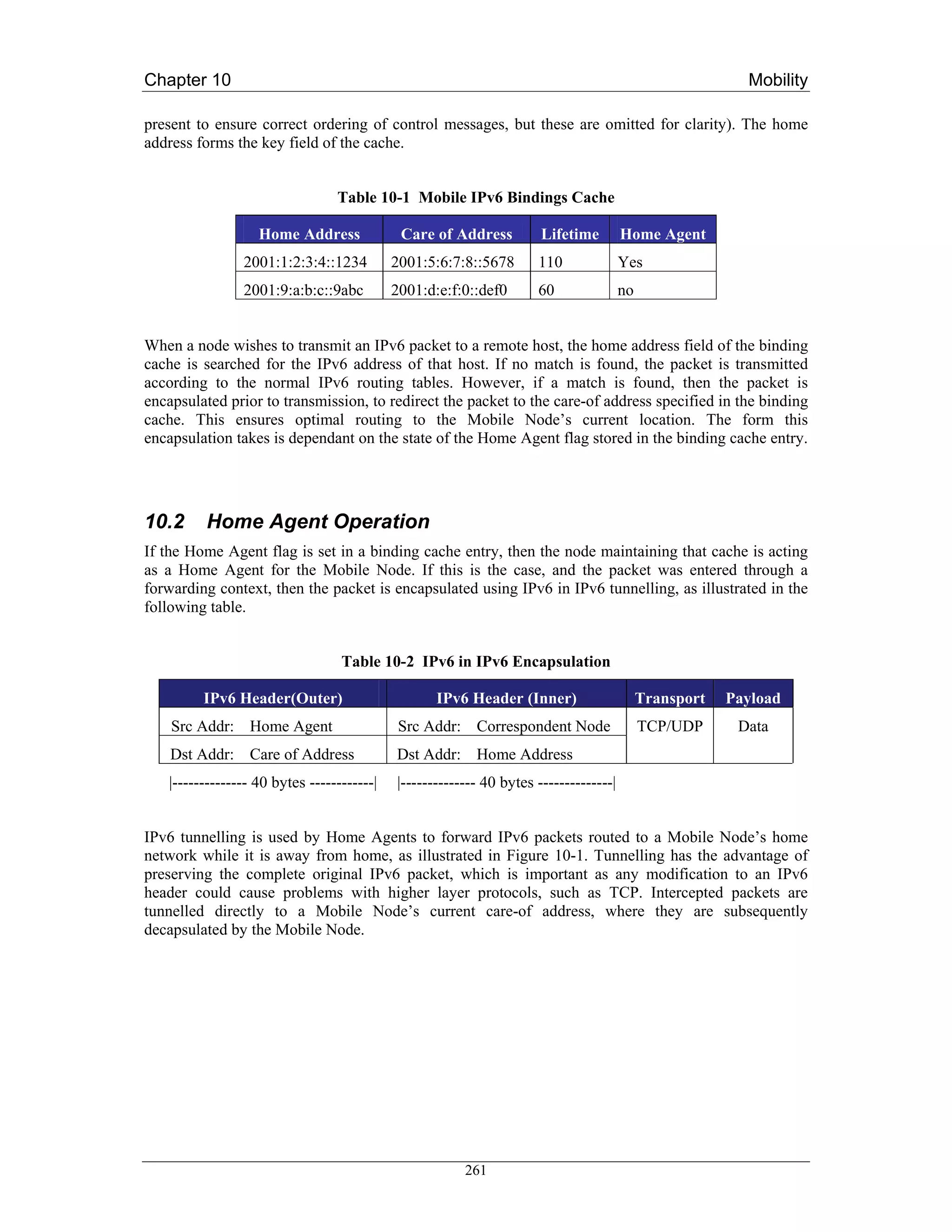
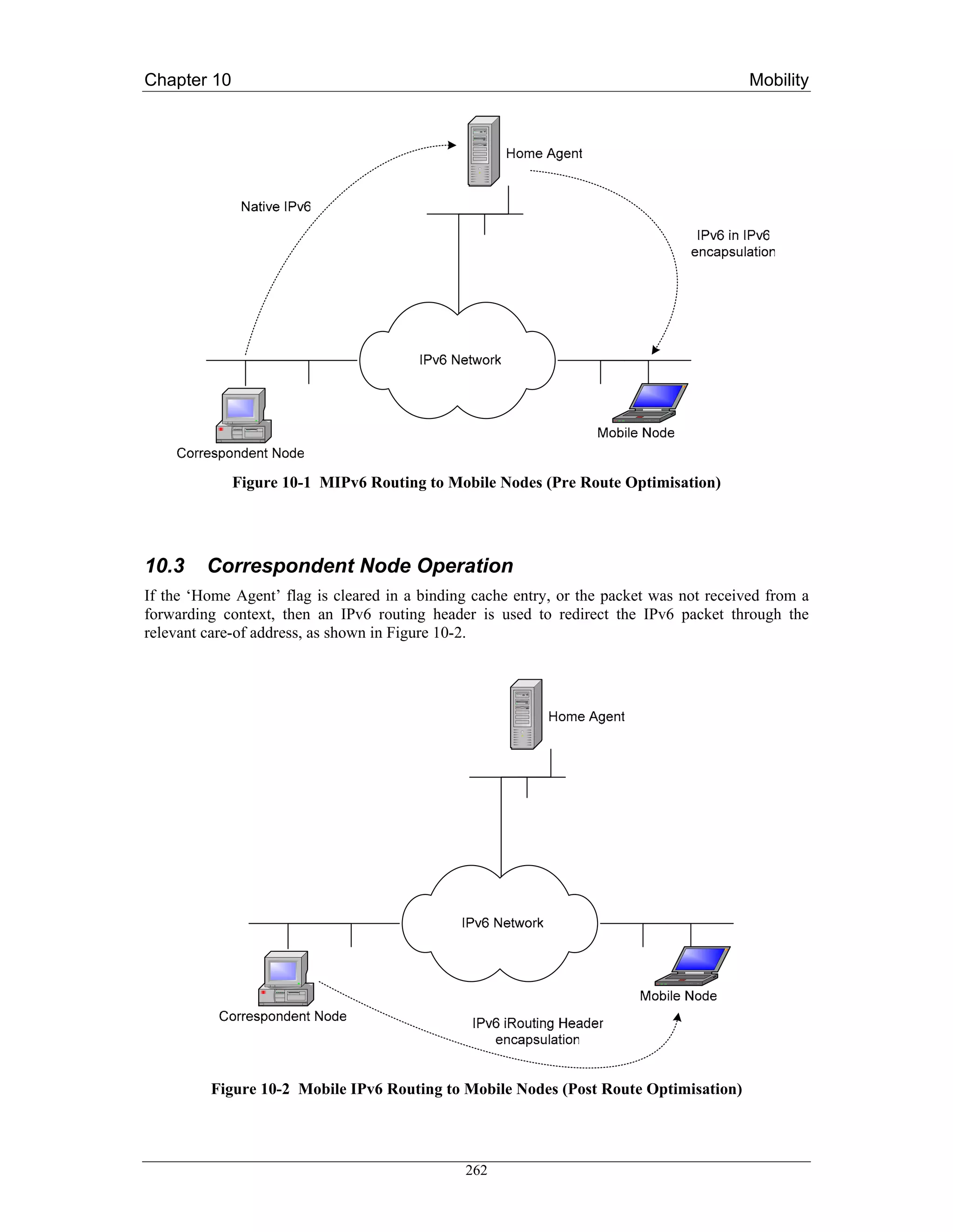
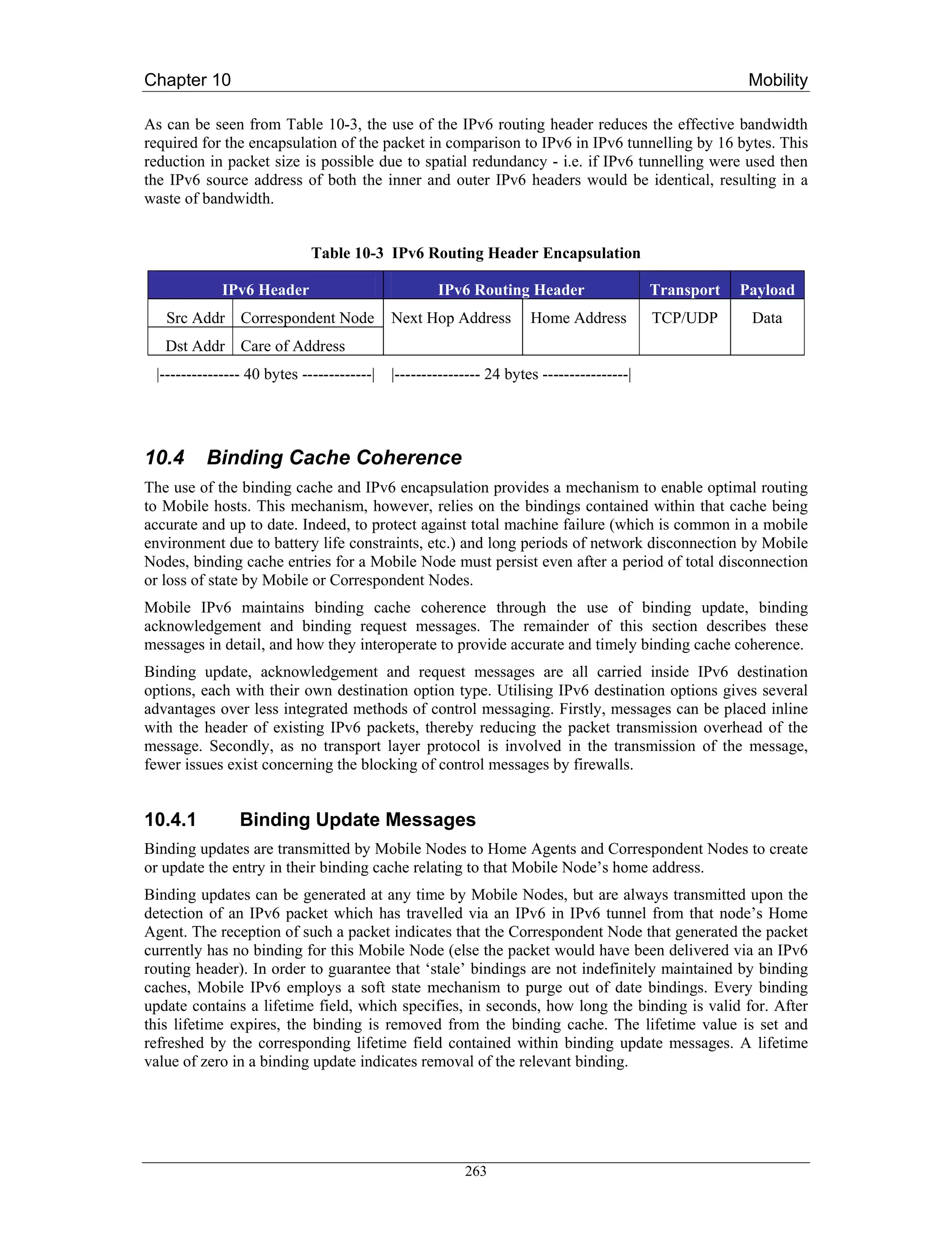
![Chapter 10 Mobility
10.4.2 Binding Acknowledgement Messages
Unlike binding updates, binding acknowledgements are sent to Mobile Nodes by Correspondent Node
and Home Agents. They provide control feedback to Mobile Nodes in response to binding updates,
and are used to provide reliable binding update delivery and to indicate any errors which are generated
during the remote processing of binding updates. Mobile Nodes match binding acknowledgements
with their corresponding binding updates by the comparison of sequence numbers.
10.4.3 Binding Request Messages
Correspondent Nodes and Home Agents detecting an entry in their binding cache which is nearing
expiry may decide to send a binding request message to the respective Mobile Node. The receipt of a
binding request message by a Mobile Node results in the transmission of a new binding update to the
source of that binding request. This mechanism enables Correspondent Nodes to avoid short periods of
sub-optimal routing, due to the expiry of an accurate binding.
10.4.4 Binding Update List
As a Mobile Node roams from network to network, it is essential that binding update messages are
transmitted to that node’s Home Agent and Correspondent Nodes as soon as possible, in order to
facilitate a fast handoff. Mobile Nodes therefore cannot rely on the soft state timeout mechanism used
in binding caches to refresh stale bindings maintained by Correspondent Nodes (typical binding
lifetimes are of the order of minutes). An additional data structure, the binding update list, is therefore
kept by Mobile Nodes, which maintains state on any Correspondent Nodes or Home Agents.
The binding update list contains one entry for every Correspondent Node or Home Agent to which a
binding update has been sent. List entries contain information such as the address and time at which
the binding update was transmitted, the state of any unacknowledged updates, the lifetime of the
binding, a Home Agent flag, and the sequence number of the last transmission. Binding list entries are
garbage collected from the binding update list as the respective binding expires.
The maintenance of the binding update list allows for significantly faster handoff performance. After a
handoff has been detected and autoconfiguration has been completed, the binding update list is
traversed, and a binding update message transmitted to every node contained within the list, thereby
updating the binding caches of any active Correspondent Nodes.
10.5 Proxy Neighbour Discovery
Since packets destined for a Mobile Node may be incorrectly routed to its home network, placing
Home Agents within an IPv6 edge router would allow the efficient interception of these packets, as
they would likely travel through that router. However, the assumption that the packets will
automatically reach this edge router cannot be relied upon. For example, consider the case of a
Correspondent Node located on a Mobile Node’s home network. If the Correspondent Node were to
send a packet to that Mobile Node, its routing table would dictate that the Mobile Node was directly
accessible, and did not require forwarding by a router. In this case, the Home Agent would not be able
to intercept the packet.
Mobile IPv6 addresses this issue through a technique call proxy neighbour discovery (proxy ND).
Neighbour Discovery [RFC2461] is a standard IPv6 protocol for the discovery of MAC addresses
from IPv6 addresses, similar in concept to the ARP protocol for IPv4. Proxy ND involves an IPv6
node masquerading as another node at the MAC layer, by falsely responding to neighbour solicitations
with its own MAC address. Home agents use proxy ND to ensure they intercept any IPv6 packets for a
Mobile Node transmitted on its home network. To accomplish this, Home Agents also maintain a
264](https://image.slidesharecdn.com/ipv6deployment-guide-110112200202-phpapp01/75/IPv6-Deployment-Guide-278-2048.jpg)
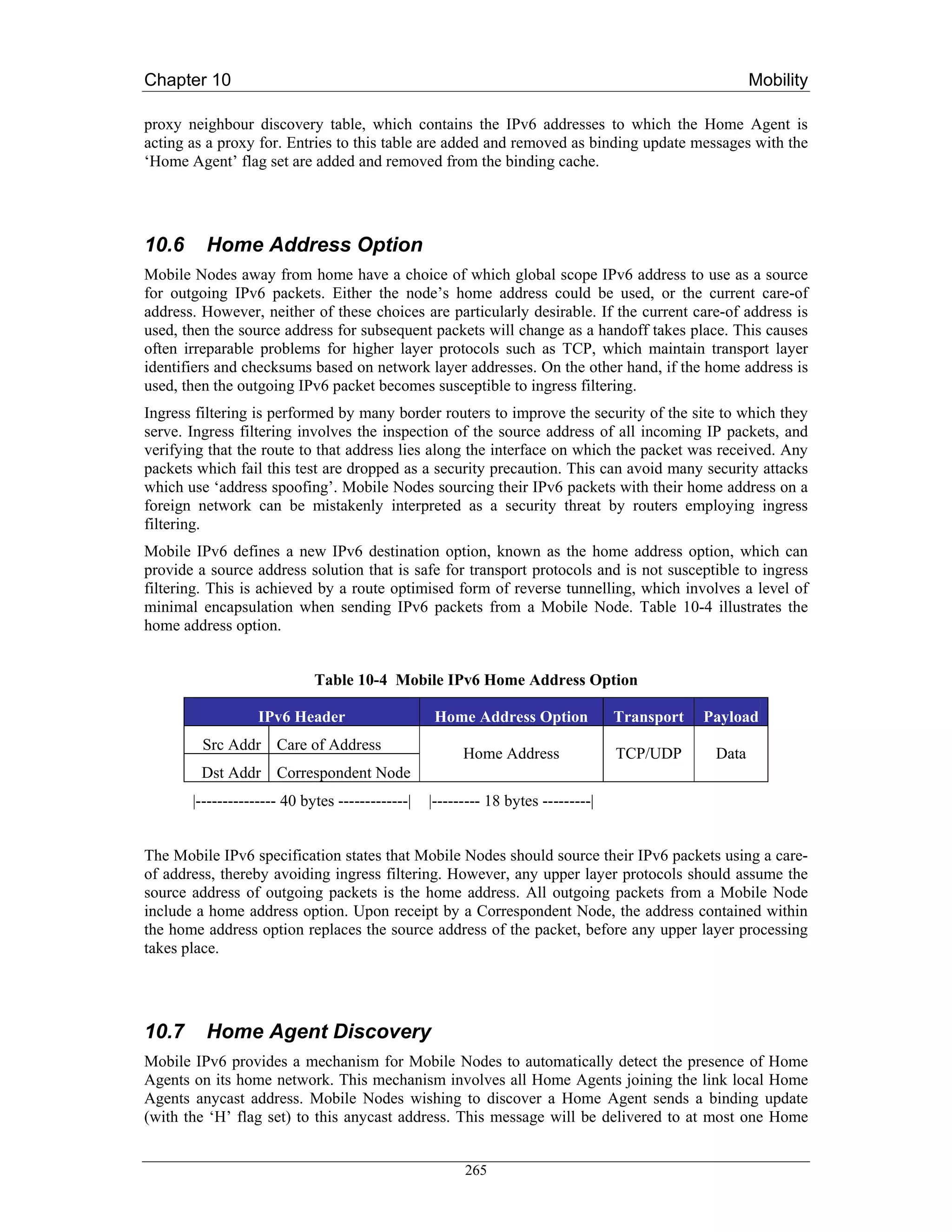
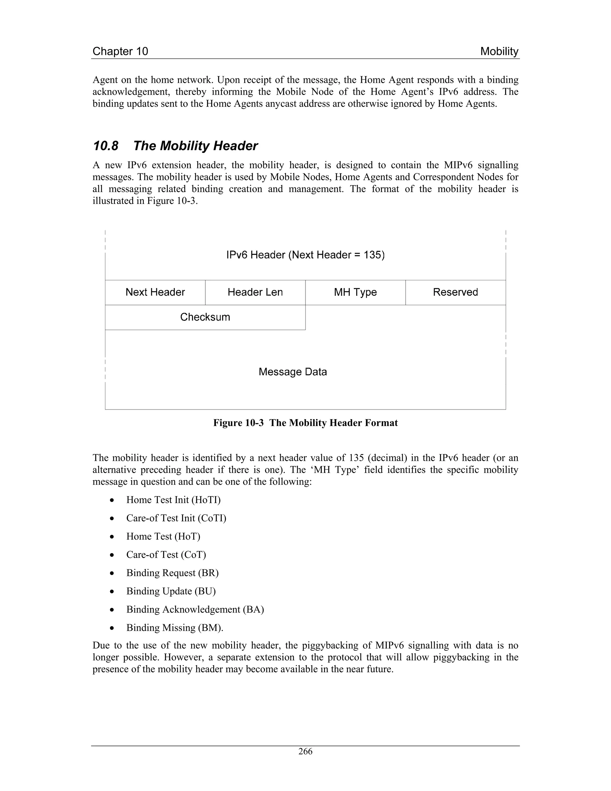
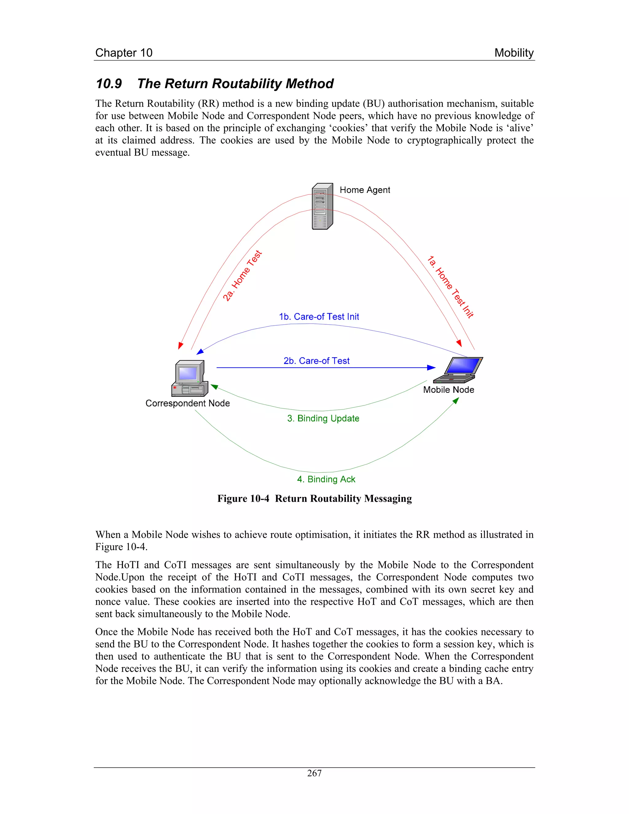
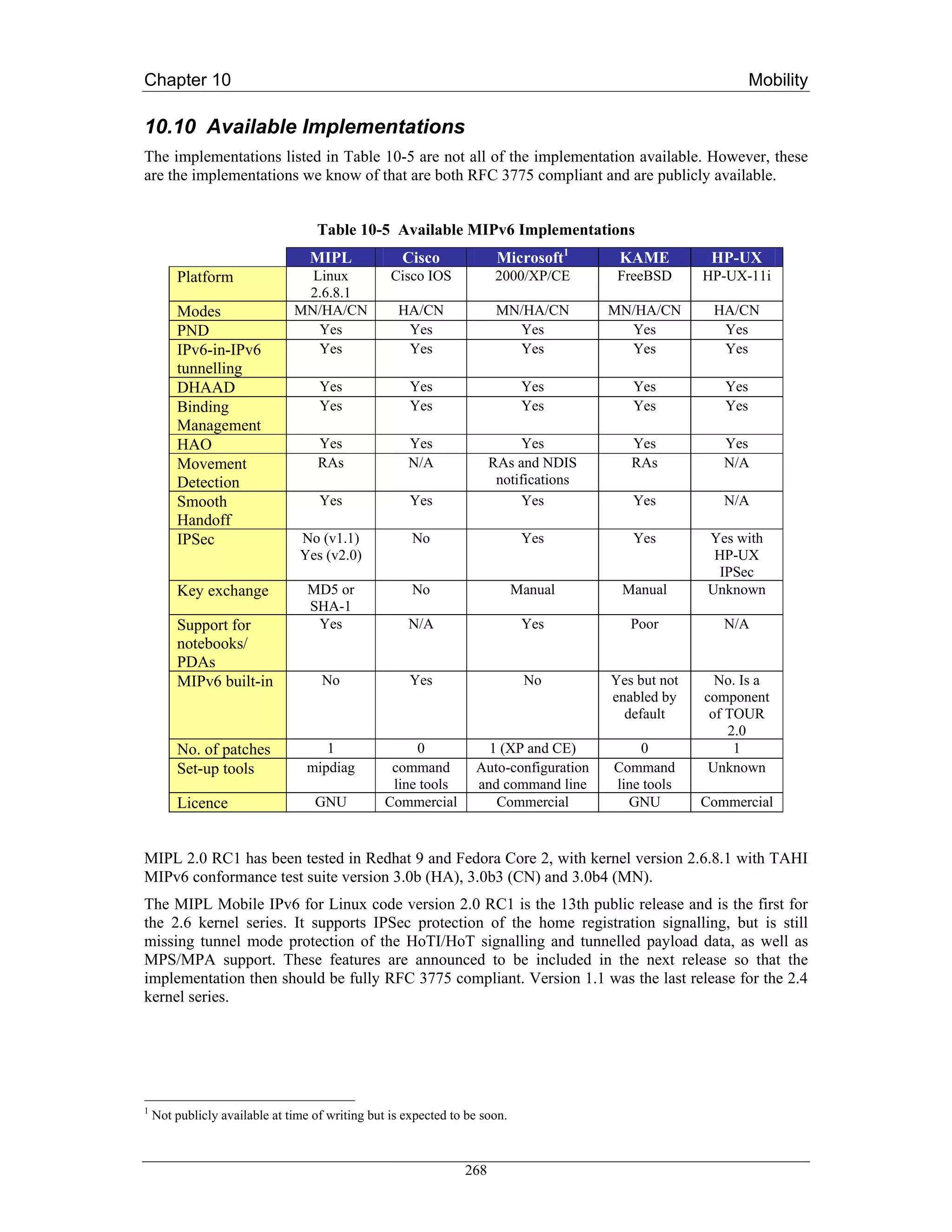
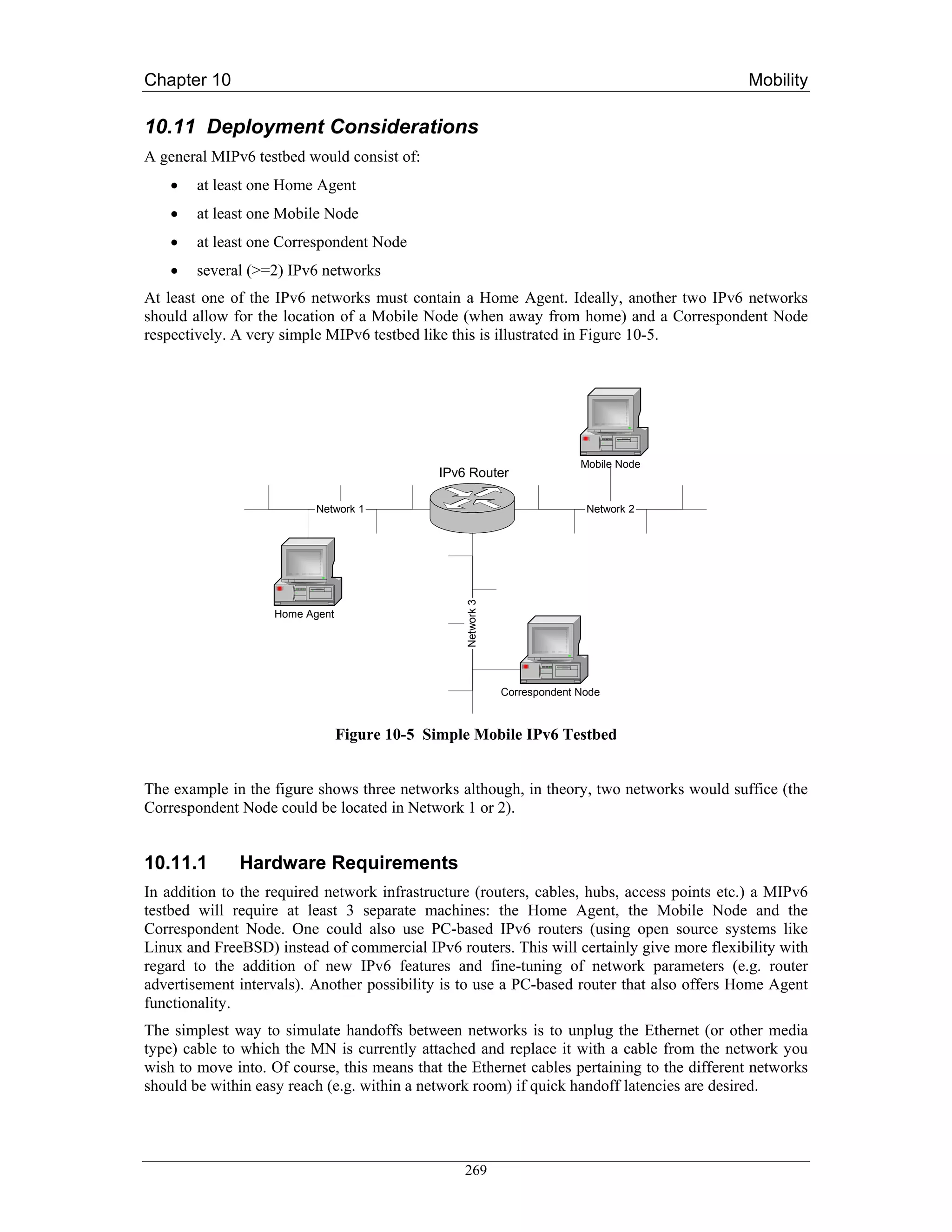
![Chapter 10 Mobility
10.12.4 Configuration
10.12.4.1 Example Configuration
The following simple example configures a router as a Mobile IPv6 Home Agent on the interfaces
Ethernet 1 and Ethernet 2. On the Ethernet2 interface, unsolicited router advertisements are configured
to be transmitted every 0.05 seconds.
ipv6 unicast-routing
!
ipv6 mobile
!
interface Ethernet1
ipv6 address 3000:1234:5678::1/64
ipv6 mobile home-agent enable
interface Ethernet2
!
ipv6 address 3000:1234:abcd::1/64
ipv6 mobile home-agent enable
ipv6 nd ra-interval msec 50
10.12.5 Configuration Commands
Global commands:
[no] ipv6 mobile
Enables Mobile IPv6. Default is disabled, all binding updates are ignored
[no] ipv6 mobile mh-number <0-255>
Changes the number used in the MIPv6 mobility header. The default is 62 which is also
used by KAME.
[no] ipv6 mobile bindings filter <acl>
Configures a binding update filter using an ACL. When an ACL is configured all
DHAAD requests and binding updates are filtered by Home Address and Destination
Address. Default is no ACL configured.
This feature may be used to deny home agent services to mobile nodes that have roamed
to particular sub-networks. When the filter blocks a binding update, a binding
acknowledgement is returned with error status "Administratively prohibited". Default is
no filter so all binding updates are accepted. Note that the filter is also applied to
Dynamic Home Agent Address Discovery messages. When blocked, these are silently
discarded.
In configuration of the ACL, the src is the CoA and the dst is the HoA.
[no] ipv6 mobile binding lifetime <secs>
Configures the maximum lifetime of a binding cache entry. Default is infinite lifetime.
272](https://image.slidesharecdn.com/ipv6deployment-guide-110112200202-phpapp01/75/IPv6-Deployment-Guide-286-2048.jpg)
![Chapter 10 Mobility
[no] ipv6 mobile binding max <int>
Specifies the maximum number of registration bindings which may be maintained
concurrently. By default, binding maximum is unset indicating unlimited. If the
configured number of home agent registrations is reached or exceeded, subsequent
registrations will be refused with the error "Insufficient resources". No existing bindings
will discarded until their lifetime has expired, even if binding maximum is set to a value
below the current number of such bindings.
[no] ipv6 mobile binding refresh
Default is 5 minutes (300 seconds).
Interface commands:
[no] ipv6 mobile home-agent enable
Enables home agent operation on the interface. By default, home agent operation is
disabled.
[no] ipv6 mobile home-agent preference <pref>
Specifies the value to be use for Preference in the Home Agent Information Option
transmitted on the interface. A value in the range -32768 to +32767 may be specified. By
default, a value for Preference of zero is assumed for home agent operation on this
interface.
[no] ipv6 nd ra-interval <secs> | msec <msecs>
Specifies the interval between sending unsolicited multicast Router Advertisements on
this interface. The value for this should be set to less than or equal to the IPv6 Router
Lifetime if this is a default router for the link. The optional sufffix msec has been
introduced to indicate that the interval has been specified in milliseconds, rather than the
default of seconds. This allows specification of the new minimum value of 0.05 seconds.
The interval should be set to a low value on interfaces providing service to visiting
mobile nodes in order to aid rapid movement detection. Note that to prevent undesirable
synchronisation with other IPv6 nodes, the value may be randomly adjusted within +/-
20%.
[no] ipv6 nd advertise-interval
Specifies whether an Advertisement Interval option should be transmitted in Router
Advertisements. This option may be used to indicate to a visiting mobile node how
frequently it may expect to receive RAs. It may use this information in its movement
detection algorithm.
[no] ipv6 nd prefix <prefix> | default
[ [<valid-lifetime> <preferred-lifetime>] |
[at <valid-date> <preferred-date>]
[off-link] [no-rtr-address] [no-autoconfig] ]
By default, all prefixes configured as addresses on the interface will be advertised in
Router Advertisements. This command allows control over the individual parameters per
prefix, including whether the prefix should be advertised or not. The default keyword can
be used to set default parameters for all prefixes. A date can be set for prefix expiry. The
valid and preferred lifetimes are counted down in real time. When the expiry date is
reached the prefix will no longer be advertised. The keyword no-rtr-address means do not
send the full router address in prefix advert; do not set the R bit.
273](https://image.slidesharecdn.com/ipv6deployment-guide-110112200202-phpapp01/75/IPv6-Deployment-Guide-287-2048.jpg)
![Chapter 10 Mobility
Show commands:
show ipv6 interface
Existing command; output extended to include home agent data where and when
applicable.
show ipv6 mobile binding [home-address <addr>]
[care-of-address <addr>]
[interface <int>]
Displays details of all bindings which match all the search criteria. If no parameters are
specified, all bindings are listed. The output is in a form where parts may be cut/pasted
into subsequent commands, e.g., clear ipv6 mobile binding.
show ipv6 mobile globals
Displays the values of all global configuration parameters associated with MIPv6, and
lists the interfaces on which home agent functionality is currently operating.
show ipv6 mobile traffic
Displays binding updates received and binding acknowledgements sent.
show ipv6 mobile home-agents [<interface> [<prefix>]]
Displays the Home Agents List for the specified interface or, if none is specified, displays
the Home Agents List for each interface on which the router is acting as a home agent. If
a prefix is specified then only those addresses matching that value will be displayed.
Clear commands:
clear ipv6 mobile binding [home-address <prefix>
| care-of-address <prefix>
| interface <int>]
Clears all bindings with the mobile nodes which match the parameters. The parameter can
be a prefix for the Care-of-Address or the Home-Address so that entire networks can be
cleared. Use /128 to clear an individual node. The interface parameter will clear all
bindings on the specified interface.
Note that when this command is used to delete bindings, the mobile node will not be
informed that its home agent is no longer acting on its behalf.
clear ipv6 mobile home-agents [<interface>]
Clears the Home Agents List on the specified interface. The list will subsequently be
reconstructed from received Router Advertisements.
clear ipv6 mobile traffic
Clears the statistics about the received binding updates and transmitted binding
acknowledgements.
Debug commands:
[un]debug ipv6 nd
Existing command; output modified to include relevant home agent data.
[un]debug ipv6 mobile bindings-cache
274](https://image.slidesharecdn.com/ipv6deployment-guide-110112200202-phpapp01/75/IPv6-Deployment-Guide-288-2048.jpg)
![Chapter 10 Mobility
Enables debugging of the bindings cache. Currently this only displays “SHUTDOWN”
when the bindings cache is shutdown.
[un]debug ipv6 mobile forwarding
Enables debugging of soft tunnel forwarding.
[un]debug ipv6 mobile home-agent
Enables Home Agent debugging.
[un]debug ipv6 mobile registrations
Enables debugging of registrations, i.e. binding updates and binding acknowledgements.
[un]debug ipv6 mobile correspondent-node
Enables Correspondent Node debugging. This currently displays when a Home Address
Options has been received.
10.12.6 Operation
Mobile IPv6 clients must be compliant with ID version 24 (or RFC 3775).
275](https://image.slidesharecdn.com/ipv6deployment-guide-110112200202-phpapp01/75/IPv6-Deployment-Guide-289-2048.jpg)
![Chapter 10 Mobility
10.13 Mobile IPv6 for Linux
Mobile IPv6 for Linux (MIPL) is an implementation that was originally developed as a software
project course in the Helsinki University of Technology (HUT), with the goal to create a prototype
implementation of Mobile IPv6 for Linux. After the course, the implementation was further developed
in the context of the GO/Core project at HUT Telecommunications and Multimedia Lab. It is an open
source implementation, has been released under GNU GPL and is freely available to anyone.
The MIPL implementation has been tested in interoperability and conformance testing events such as
the ETSI IPv6 Plugtests and TAHI Interoperability events.
10.13.1 How to get it
In Linux, the standard IPv6 stack is included in the mainstream kernel distribution. However, you have
to patch the kernel if you want Mobile IPv6 features. Therefore, a MIPL release is usually compatible
only with a specific kernel revision (unless between Linux revisions the kernel code that has to be
patched has not changed). MIPL v1.1, which is described in this section, requires Linux kernel version
2.4.26. MIPL v1.1 is based on MIPv6 specification as described in RFC 3775 [RFC3775]. The most
recent MIPL release, MIPL 2.0 RC1 requires Linux kernel version 2.6.8.1. It is recommended to use
MIPL 1.1, at the time of writing MIPL 2.0 RC1 is a preview release and therefore very much still
work in progress.
The kernel 2.4.26 can be obtained from your favourite kernel mirror site, e.g. http://www.kernel.org
The MIPL patch mipv6-1.1-v2.4.26tar.gz can be obtained from http://www.mobile-ipv6.org
10.13.2 Installation
The following steps describe the MIPL installation (based on the README and INSTALL files of the
package).
1. Unpack the MIPL tar file, for example in the /usr/src directory. This will create the
directory /usr/src/mipv6-1.1-v2.4.26
2. Go to the Linux source directory (e.g. /usr/src/linux)
3. Apply the MIPL kernel patch:
“patch -p1 < /usr/src/mipv6-1.1-v2.4.26/mipv6-1.1-v2.4.26.patch”
4. “make xconfig” (or config or whatever you prefer) to configure the kernel: you should
have the following settings in your configuration:
CONFIG_EXPERIMENTAL=y
CONFIG_SYSCTL=y
CONFIG_PROC_FS=y
CONFIG_MODULES=y
CONFIG_NET=y
CONFIG_NETFILTER=y
CONFIG_UNIX=y
CONFIG_INET=y
CONFIG_IPV6=m
CONFIG_IPV6_SUBTREES=y
276](https://image.slidesharecdn.com/ipv6deployment-guide-110112200202-phpapp01/75/IPv6-Deployment-Guide-290-2048.jpg)
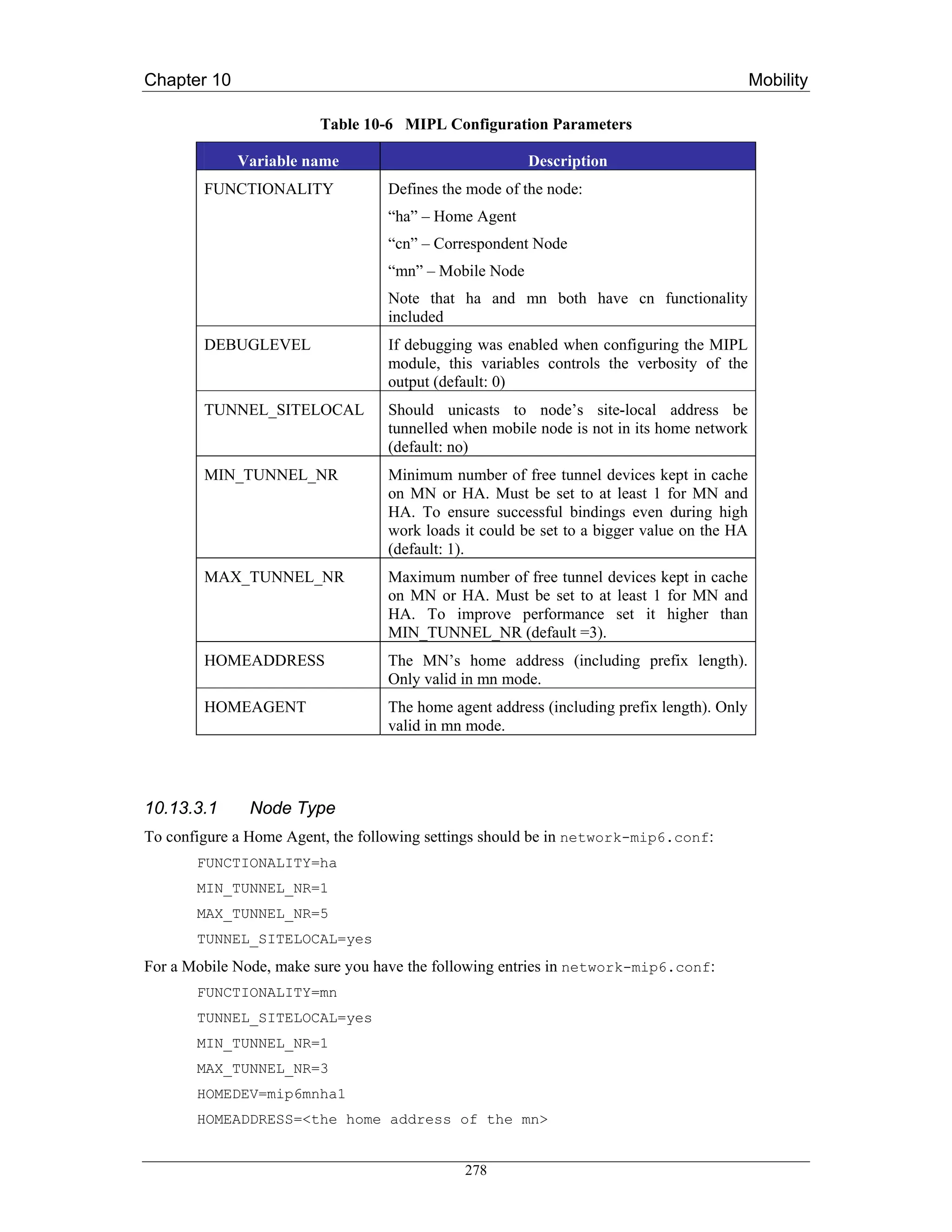
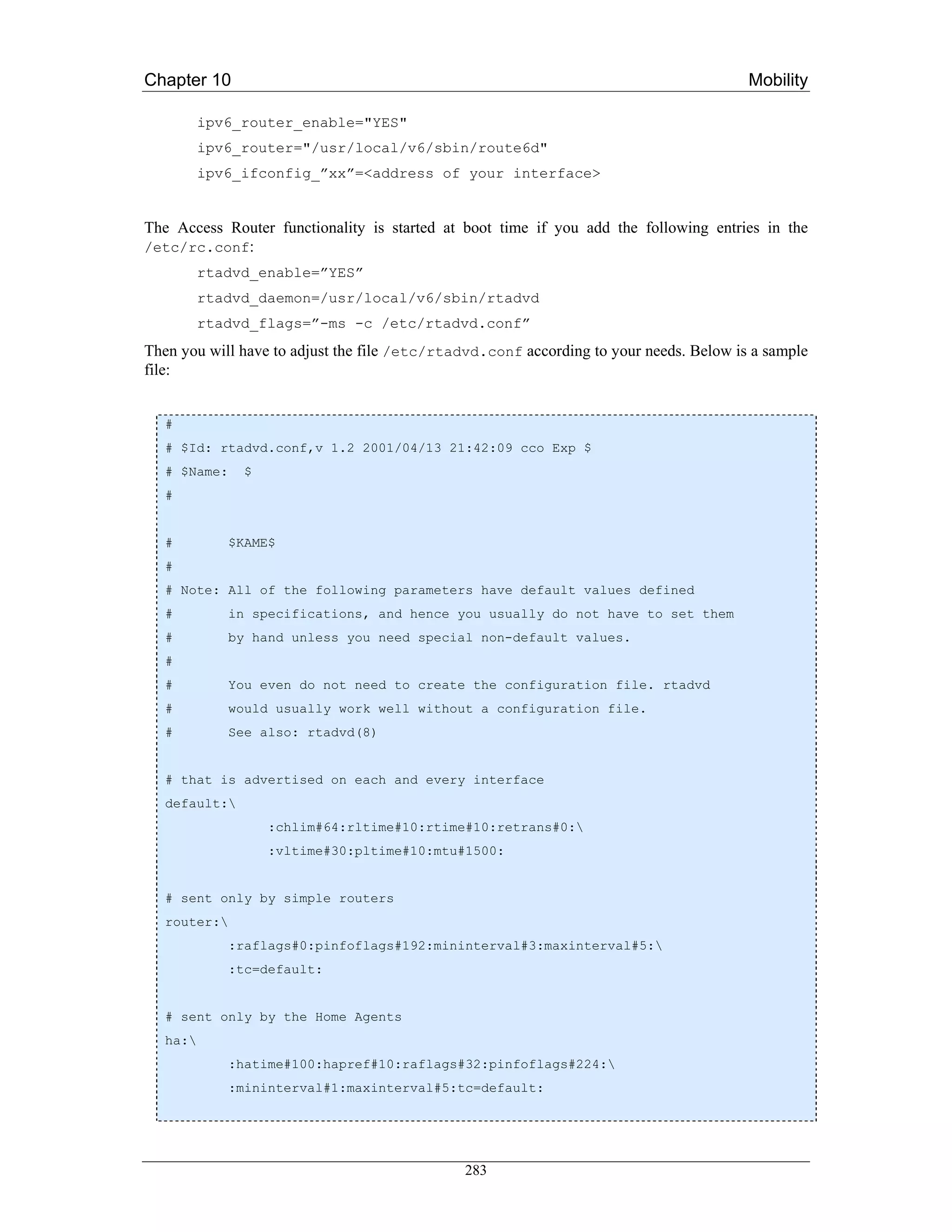
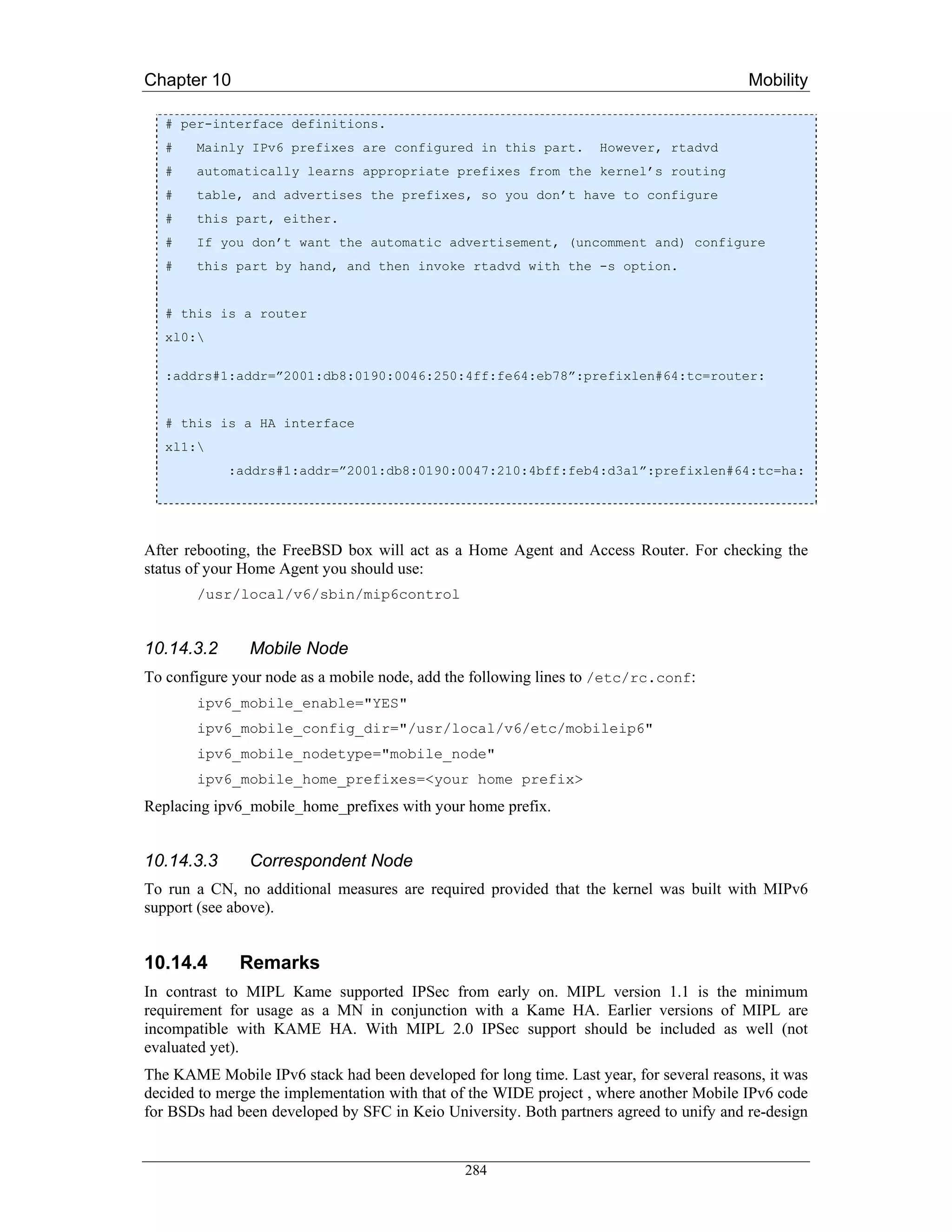
![Chapter 10 Mobility
their implementations. The resulting new MIP6 code is called shisa which confirmed its
interoperability during the latest ETSI IPv6 plugtest event.
The current shisa implementation is based on RFC 3775, RFC 3776 [RFC3776], RFC 3963
[RFC3963] and draft-wakikawa-mobileip-multiplecoa-04 [WUEN05]. It works on FreeBSD 4.10,
FreeBSD 5.3 and NetBSD 1.6.2. But note that FreeBSD 4.10 will not be supported in kame snap soon
as announced on snap-users mailing list.
285](https://image.slidesharecdn.com/ipv6deployment-guide-110112200202-phpapp01/75/IPv6-Deployment-Guide-299-2048.jpg)
![Chapter 11 Applications
Chapter 11
Applications
A number of middleware and user applications were developed or ported by the 6NET project. These
included the SIP-based telephony system (including a PSTN gateway), the AccessGrid conferencing
tool (including an IPv4-IPv6 gateway), IPv6 versions of the IBM WebSphere e-business applications,
an IPv6 version of the FLUTE multicast file transfer tool, and MIPv6-based video streaming for
PDAs. The 6NET project also created IPv6 versions of the Globus Toolkit (GT3.x) which is used to
develop Grid-aware applications (e.g., IPv6 WeatherStation and eProtein), and the Open H.323
Toolkit, used to develop an IPv6 version of GnomeMeeting. Other network management tools such as
NetSNMP, MRTG, OpenEye, Smokeping and Weathermap have been developed or ported for traffic
measurement and visualisation purposes.
Figure 11-1 Partial Screenshot of the Applications Database
Deliverable D5.1 [D5.1] of the 6NET project listed the applications initially identified as candidates to
run on the 6NET IPv6 network. Since the development and porting of applications to support IPv6 is
not a static activity, it is very difficult, if not impossible, to capture the ever-evolving status of the
different applications mentioned in a single document.
Therefore, the Applications workpackage of 6NET decided that the applications list and current status
would be in the form of a web page. This approach enables application owners to keep the status of
286](https://image.slidesharecdn.com/ipv6deployment-guide-110112200202-phpapp01/75/IPv6-Deployment-Guide-300-2048.jpg)
![Chapter 11 Applications
their porting effort up to date and additionally allows interested users to keep track of the status,
knowing that it is more up to date than a project deliverable downloaded from a web site or indeed,
this book.
The up-to-date list of 6NET applications is therefore available at the following address:
http://apps.6net.org/WP5Apps (Figure 11-1 shows a partial screenshot). This site also provides the
results of the trials performed on each application through Test Evaluation Forms (TEFs) according to
the methodology described in Deliverable D5.5 [D5.5].
Instead of listing those applications available on the above website, this chapter outlines the important
changes that IPv6 brings to network APIs in C and other programming languages. This will be of
interest to deployers of IPv6 looking to develop new or port existing applications for their
organisation.
11.1 The new BSD Sockets API
BSD Sockets is by far the most popular application programming interface (API). The name pays
tribute to its authors – it was created at the University of California in Berkeley, originally for BSD
Unix, but later it was ported to other branches of Unix and also to MacOS, MS Windows and even
PalmOS. Applications of BSD Sockets are not limited to IP, although other uses have been rare. It is
not an exaggeration to say that the application side of the Internet is built on this API.
It is well-known that to Unix, everything looks like a file. BSD Sockets API uses this paradigm for
communication between programs. Its fundamental program object – the socket – represents a
communication channel through which two programs can exchange data using standard file
descriptors.
Even though the original BSD Sockets API was designed as protocol-independent, the astronomical
size of IPv6 addresses was something that apparently exceeded even the wildest dreams of its
developers. Data structures of the original BSD Sockets left some space for protocol addresses longer
than the 32 bits of IPv4, not enough though to accommodate the quadruple of that size and other
information that is needed for IPv6. It was thus necessary to update and extend the API. The IPv6
working group at IETF utilised this opportunity for an overall consolidation and streamlining of the
API. Their most recent – and hopefully more or less final – result is RFC3493 [RFC3493]. The new
API enables the programmer to write applications for both IPv4 and IPv6 using a single programming
framework. In addition, the IPv6 working group defined an API for advanced IPv6 applications using
raw sockets [RFC3542] although the vast majority of TCP and UDP based applications will only
require the API defined in RFC 3493.
We are going to describe the data structures and function using the formalism of the C language, as
they appear in Unix header files. Equivalent APIs are available for most of the common programming
languages and we will show some examples at the end of this section.
A detailed explanation of BSD Sockets programming is outside the scope of this section, we will
mainly concentrate on the changes introduced by the new API for IPv6. Therefore, we assume the
reader has at least a basic idea about the original API, which has been covered, for example, in the
classic book “Unix Network Programming” [Ste97]. Other valuable sources of information are the
Unix on-line manuals.
11.1.1 Principles of the New API Design
Authors of the new API realised it was not sufficient to treat IPv6 as just another protocol family
supported by the socket API. First, since most application and services are common to IPv4 and IPv6,
287](https://image.slidesharecdn.com/ipv6deployment-guide-110112200202-phpapp01/75/IPv6-Deployment-Guide-301-2048.jpg)
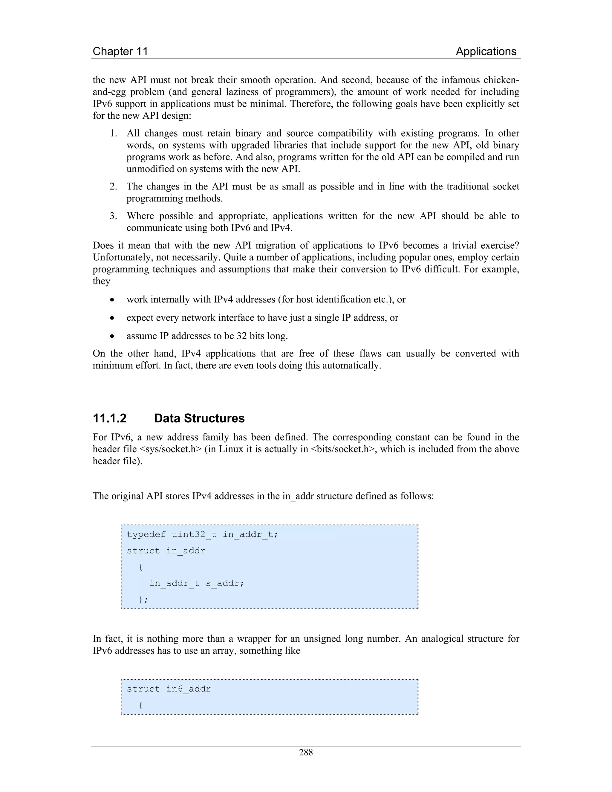
![Chapter 11 Applications
uint8_t s6_addr[16];
};
In reality, looking into the header file <netinet/in.h> we find the definition is more complicated. For
efficiency reasons, it uses an union of several variants which can be used to force word alignment for
all processor architectures. Normally this is nothing a user of the API should care about.
A more interesting situation is with socket addresses. The main functions of BSD Sockets are
universal across all protocol families. The socket addresses as parameters of those functions are in the
form of opaque pointers to an abstract structure sockaddr. Consequently, the pointers that are passed
as arguments must be properly typecast.
As we know, addresses of the classical IP sockets consist of the pair (IP address, TCP/UDP port). The
corresponding structure sockaddr_inis defined as follows:
struct sockaddr_in
{
unsigned short int sin_family; /* Address family */
uint16_t sin_port; /* Port number */
struct in_addr sin_addr; /* Internet address */
unsigned char sin_zero[8]; /* Padding */
};
The structure is padded to the size of the abstract structure sockaddr so that there is some space for
increasing the address size. However, for IPv6 addresses these eight spare bytes are not enough. IPv6
socket address thus uses a new structure:
struct sockaddr_in6
{
unsigned short int sin6_family; /* Address family */
uint16_t sin6_port; /* Port number */
uint32_t sin6_flowinfo; /* Traffic class and flow info */
struct in6_addr sin6_addr; /* IPv6 address */
uint32_t sin6_scope_id; /* IPv6 scope-id */
};
Beyond reserving the space for IPv6 addresses, two new members have been added as well:
• sin6_flowinfo contains data from two IPv6 header fields, traffic class and flow label.
• sin6_scope_id specifies network interfaces belonging to the same address scope as the address
in sin6_addr.
Needless to say, all multi-byte members of the structures (including the IPv6 address) must be stored
in the Network Byte Order (NBO), which is in the context of microprocessor architectures known as
289](https://image.slidesharecdn.com/ipv6deployment-guide-110112200202-phpapp01/75/IPv6-Deployment-Guide-303-2048.jpg)
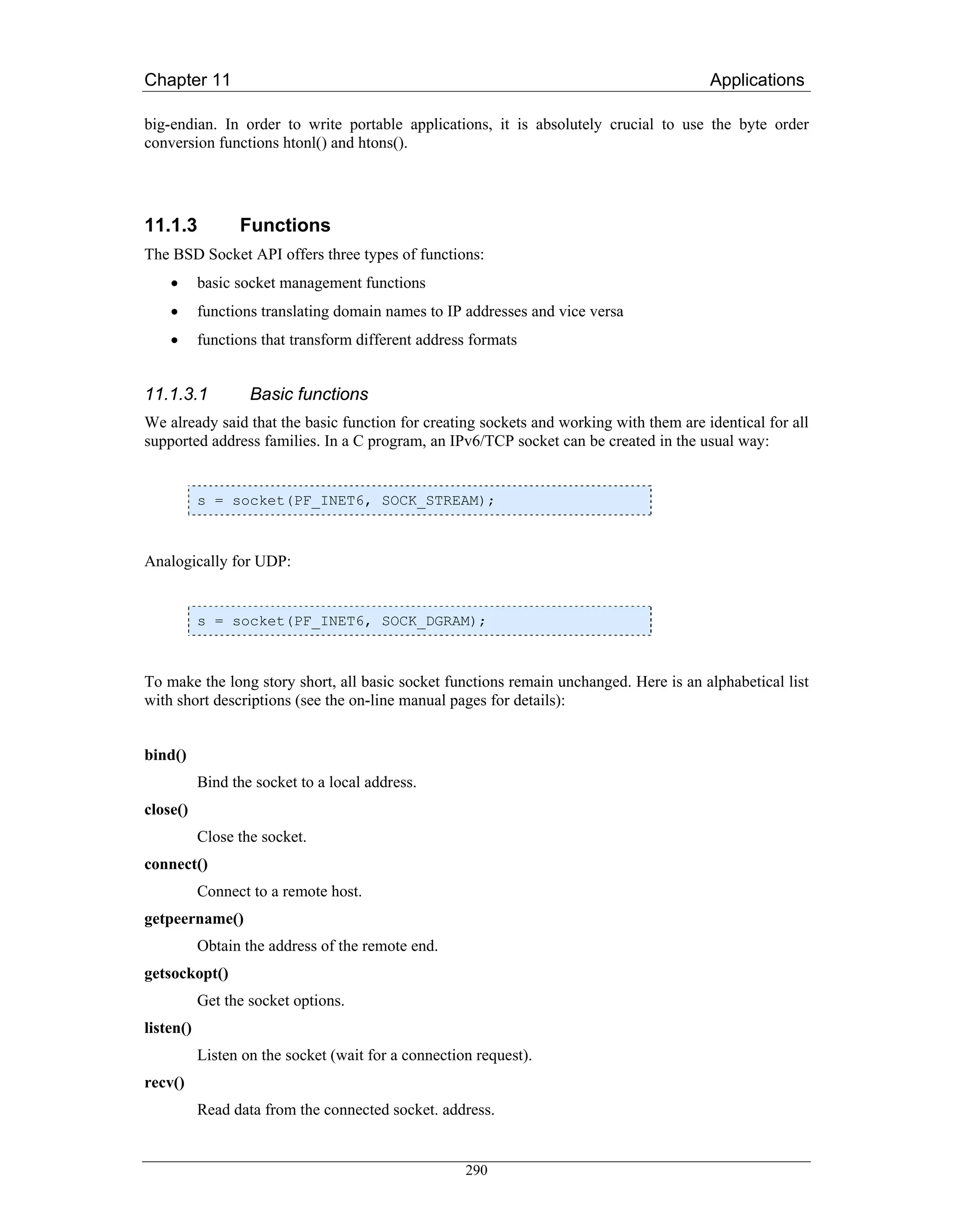
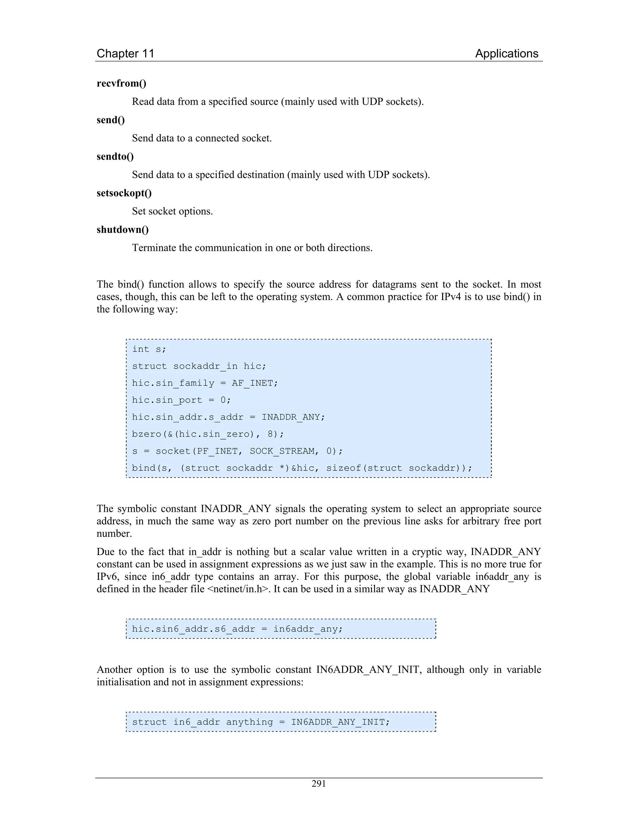
![Chapter 11 Applications
A similar issue arises in the case of the loopback interface whose address can be used as either source
or destination address. Again, for IPv4 we have the symbolic constant INADDR_LOOPBACK
corresponding to 127.0.0.1, whereas for IPv6 we have to choose one of the two alternatives:
• global variable in6addr_loopback
• symbolic constant IN6ADDR_ANY_INIT useful only for variable initialisation.
11.1.3.2 Name-address translations
Few network applications written for IPv4 can dispense with the use of the Domain Name System
(DNS) and, for that matter, function gethostbyname(). In the IPv6 context, though, this function is
useless. Every IPv6-enabled host is likely to have, apart from one or more IPv6 addresses, also an
IPv4 address and both A and AAAA records may belong to the same domain name. The
gethostbyname() function provides no option for specifying which record we are interested in, or
whether we want both. In 1999, RFC 2553 [RFC2553] thus came up with new functions for DNS
look-ups, namely getipnodebyname and getipnodebyaddr. Unfortunately, they turned out to have other
shortcomings (lack of support for address scopes). As a result, in RFC 3493 (which obsoletes RFC
2553) these two functions were deprecated. All in all, we have been left with just one function for
DNS look-ups, getaddrinfo(). This function has its origins in the IEEE POSIX standard 1003.1g and is
protocol independent. Along with gethostbyname(), it is also a replacement for the getservbyname()
function. The prototype looks as follows:
int *getaddrinfo(const char *nodename, const char *servname,
const struct addrinfo *hints, struct addrinfo **res);
The function returns either zero, which indicates success, or various error codes. The result of the
DNS query is passed to the calling program via the res argument, a pointer to a unidirectional list of
structures of the addrinfo type defined in <netdb.h> as
struct addrinfo
{
int ai_flags; /* Input flags. */
int ai_family; /* Protocol family for socket. */
int ai_socktype; /* Socket type. */
int ai_protocol; /* Protocol for socket. */
socklen_t ai_addrlen; /* Length of socket address. */
struct sockaddr *ai_addr; /* Socket address for socket. */
char *ai_canonname; /* Canonical name. */
struct addrinfo *ai_next; /* Pointer to next in list. */
};
The ai_next member points to the next item in the list (the last one has NULL here). Memory must be
allocated dynamically for this list and so we have to keep in mind (at least in C) to release this
memory when it is no more needed. This is done using the freeaddrinfo() function.
292](https://image.slidesharecdn.com/ipv6deployment-guide-110112200202-phpapp01/75/IPv6-Deployment-Guide-306-2048.jpg)
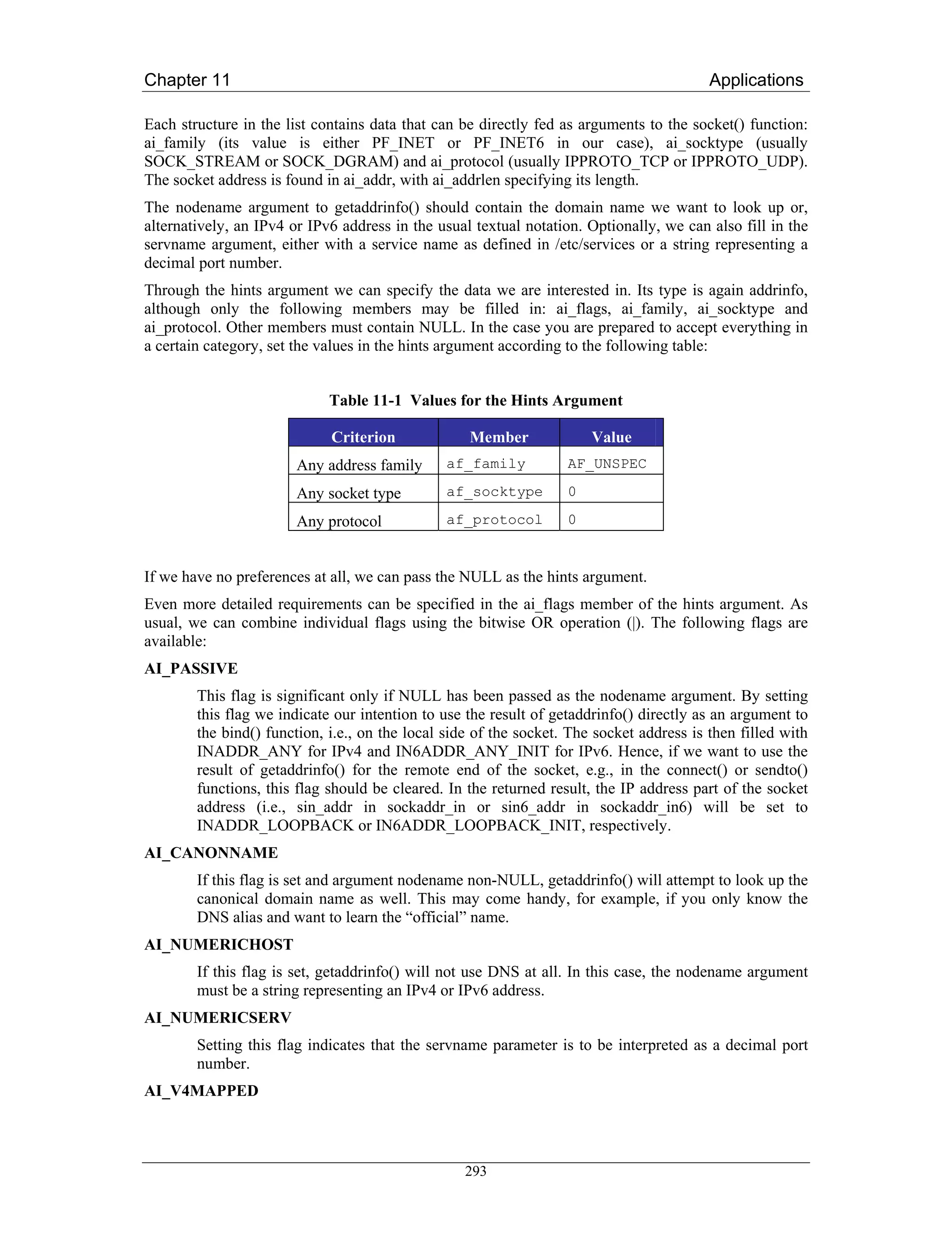
![Chapter 11 Applications
NI_NUMERICHOST
With this flag on, getnameinfo() will set *node to a string representing an IP address. To an
IPv6 address, a zone identifier may also be appended as described [RFC4007], for example
“fe80::1%eth0”.
NI_NUMERICSCOPE
If this flag is set together with the previous one, the zone within an address scope will be
expressed as a zone index (for example, an interface index) instead of a symbolic zone
identifier(e.g., eth0).
NI_NUMERICSERV
Similarly, with this flag on, the *service string will be filled with a decimal port number
instead of a symbolic service name, for example “80” instead of “www”.
NI_NAMEREQD
If this flag is set and no domain name can be found for the IP address in *sa, getnameinfo will
return a non-zero error code, instead of just copying the IP address into *node.
NI_DGRAM
This flag indicates a connectionless service (SOCK_DGRAM). By default, a connection-
oriented service (SOCK_DGRAM) is assumed.
11.1.3.3 Address format conversions
When working with IPv4 and IPv6 addresses, one often needs to convert their human-readable textual
representation into a binary numeric form and vice versa. The following two functions serve this
purpose:
int inet_pton(int af, const char *src, void *dst);
const char *inet_ntop(int af, const void *src,
char *dst, socklen_t size);
The inet_pton function converts the textual representation into binary and inet_ntop the other way
around. The binary form always uses the Network Byte Order.
The af argument specifies the address family (AF_INET or AF_INET6) and through the src and dst
arguments the functions are given two pointers – src points to the buffer with the input value and dst to
the buffer where the result is to be stored. Finally, the size argument of inet_ntop gives the size of the
buffer allocated for the result. This buffer should be long enough to store a textual representation of
any IPv4 or IPv6 address (depending on the chosen address family).
Function inet_pton returns 1 if the conversion was successful, 0 if the input value is considered wrong
and -1 in the case of an unknown address family. In contrast, inet_ntop signals a failure by returning
the NULL pointer, whereas if the conversion succeeds, the dst pointer is passed as the function return
value, too.
295](https://image.slidesharecdn.com/ipv6deployment-guide-110112200202-phpapp01/75/IPv6-Deployment-Guide-309-2048.jpg)
![Chapter 11 Applications
11.1.4 IPv4 Interoperability
Users of IPv6 certainly want too keep the same level of connectivity to the Internet they used to have
without IPv6. The application programmer can ensure, by means of the getaddrinfo() and
AI_V4MAPPED flag, that a DNS name resolves at least into an A record if no AAAA records are
available. An IPv6 application can also initiate the communication with an IPv4 node by using an
IPv4-mapped IPv6 address in the sockaddr_in6 structure. The library implementing BSD Sockets API
must then translate on the fly between IPv4 and IPv6 so that the IPv4 node receives only IPv4
datagrams and, conversely, translate the IPv4 datagrams coming from the IPv4 node into the IPv4-
mapped IPv6 addresses.
As a result, applications utilising IPv6 sockets usually do not have to distinguish between native and
IPv4-mapped IPv6 addresses. For those that do, the IN6_IS_ADDR_V4MAPPED macro is defined in
<netinet/in.h>.
11.2 Other Programming Languages
In the previous section we described the BSD Sockets API using the syntax of the C programming
language. However, the API is by no means limited to C, and most modern languages implement it as
well. In fact, many of them make socket programming considerably easier. In the following
subsections we demonstrate it on two popular interpreted languages – Python and Perl.
11.2.1 Python
Python implements the BSD Sockets API in the socket module in its basic system library. Python adds
an object-oriented interface that makes the API particularly easy to use. Otherwise, the
implementation follows RFC 3493 pretty closely. The module also defines all the constants specified
in RFC 3493 like AF_INET or AI_V4MAPPED. Documentation is available online as a part of the
Python Library Reference [Pyth-Lib].
As in C, sockets are created using the socket() function, which returns a socket object. Following the
object-oriented paradigm, all other socket functions are implemented as methods and applied to the
socket object via messages. This will be demonstrated in the example below.
Python implementation also uses a simpler form of socket addresses.:
• IPv4 sockets are represented as a pair (address, port)
• IPv6 sockets are represented as a four-tuple (address, port, flowinfo, scopeid), where flowinfo
and scopeid correspond to the sin6_flowinfo and sin6_scope_id members of the sockaddr_in6
structure.
Finally, the handling of error conditions was integrated into the Python system of exceptions. Instead
of signalling a failure by returning an error code, as in C, Python functions raise an exception that the
application can handle in a specific way.
The following example consists of two simple programs that demonstrate the Python way of using the
BSD Sockets API. They should work with Python version 2.2.1 or higher. The programs realise
connectionless communication using IPv6 and UDP. Both programs first execute the getaddrinfo()
function to obtain the socket address and create the socket. The sender application then periodically
sends a short message to a named peer using the sendto() function. The receiver binds the socket
address to the socket and thus starts listening on the predefined port 54321, and then enters an infinite
loop waiting for the data and printing them on the terminal.
296](https://image.slidesharecdn.com/ipv6deployment-guide-110112200202-phpapp01/75/IPv6-Deployment-Guide-310-2048.jpg)
![Chapter 11 Applications
A usual disclaimer applies here: real-life programs should also care about possible errors and define
appropriate exception handlers. Also, a more graceful termination might be recommended – our
programs must be abruptly terminated by pressing Ctrl-C.
11.2.1.1 Sender
from socket import *
import time
peer = “www.cesnet.cz”
port = 54321
af,styp,proto,cn,sa = getaddrinfo(peer, port,
AF_INET6, SOCK_DGRAM)[0]
s = socket(af,styp,proto)
while 1:
s.sendto(“IPv6 rocks!”, sa)
time.sleep(1)
11.2.1.2 Receiver
from socket import *
import time
maxlen = 512
port = 54321
af,styp,proto,cn,sa = getaddrinfo(None, port,
AF_INET6, SOCK_DGRAM,
0, AI_PASSIVE)[0]
s = socket(af,styp,proto)
s.bind(sa)
while 1:
recv = s.recvfrom(maxlen)
print “Node”, recv[1][0], “said:”, recv[0]
297](https://image.slidesharecdn.com/ipv6deployment-guide-110112200202-phpapp01/75/IPv6-Deployment-Guide-311-2048.jpg)


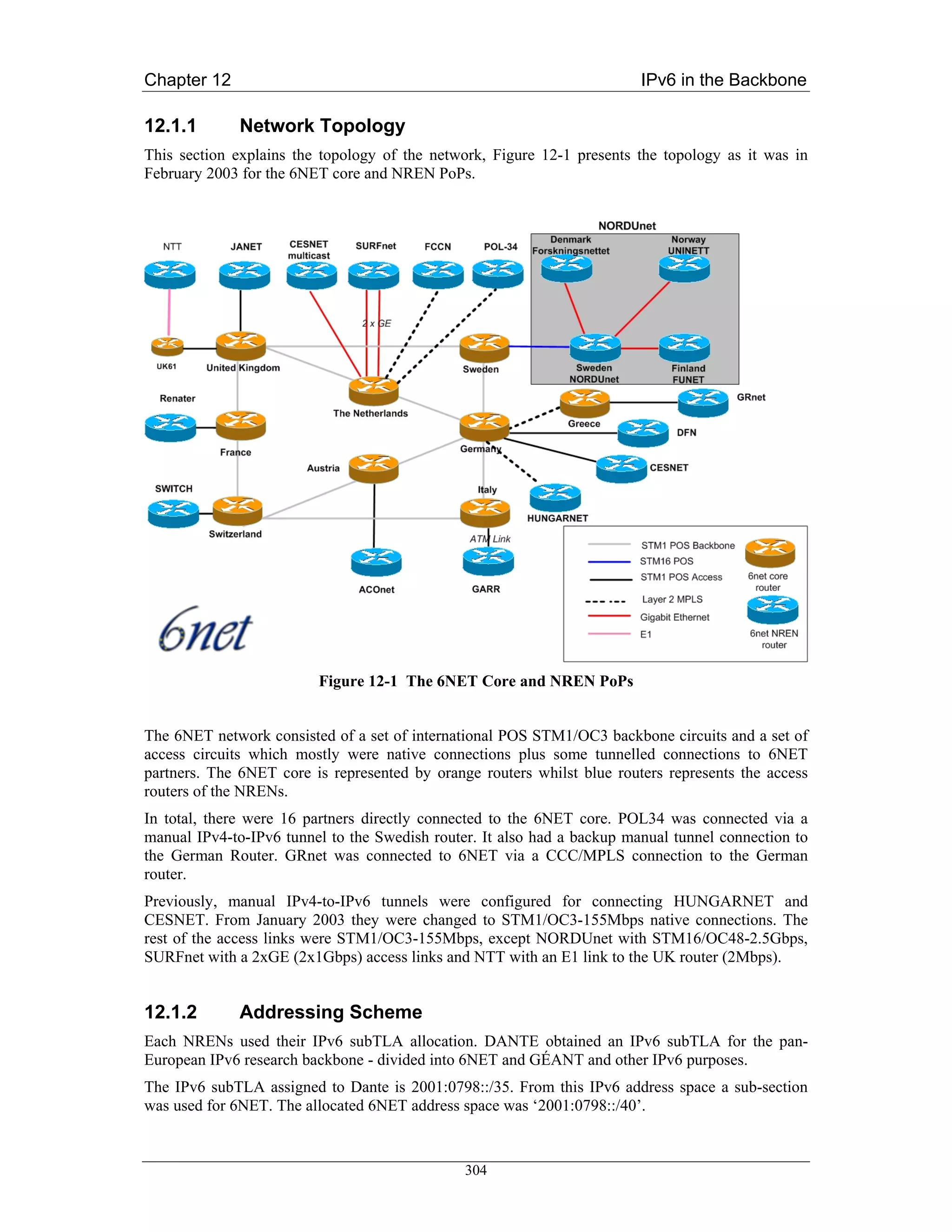
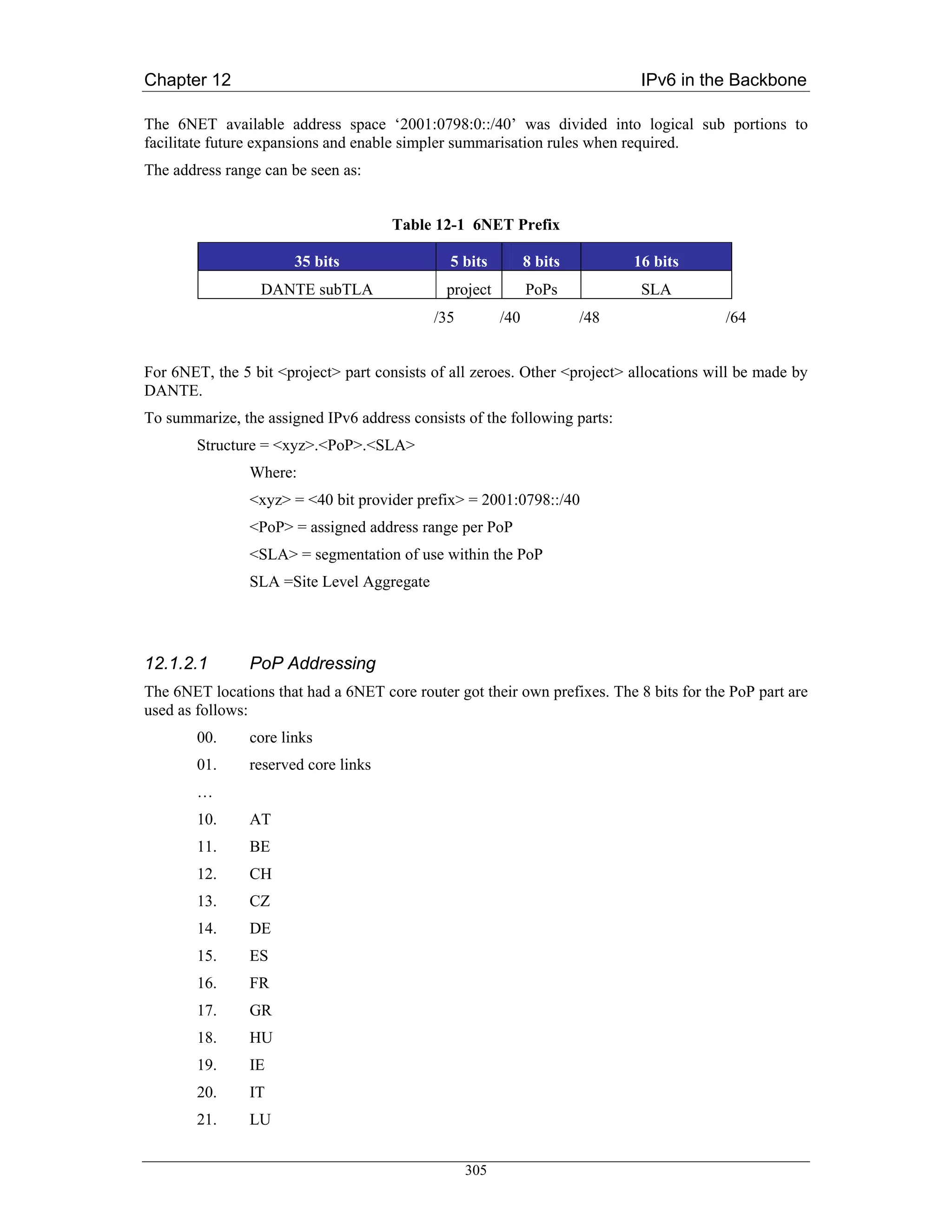

![Chapter 12 IPv6 in the Backbone
The potential future use of a /127 address space (or other address space) which initially seems to use
only minimal address range will not work in the long run. More study material can be found in RFC
3627 [RFC3627].
It is also possible to use /128 on point-to-point links. The drawback here is that in Cisco IOS you need
to add a static route to the remote side.
For Switzerland with <PoP>=12 this would give the following prefixes:
Table 12-4 Switzerland Prefixes
Use Prefix
Loopback addresses: 2001:0798:0012:0000::/56
Intra-PoP Point-to-points: 2001:0798:0012:0100::/56
Connections to NREN PoP: 2001:0798:0012:0200::/56
External 6NET connection: 2001:0798:0012:0300::/56
PoP LANs: 2001:0798:0012:0400::/56
12.1.2.2 Loopback Addresses
In networking environments, it is seen as good practice to give each device an IPv6 loopback address.
This is an IPv6 address that is not directly assigned to any physical interface and will typically be
reachable when the networking appliance (in this case a router) is up and running.
This loopback address is also used for operational and management actions on the equipment and for
routing protocols like eBGP, which use these addresses for terminating the peering sessions.
Loopback addresses typically have a prefix mask of /128. This avoids unnecessary unused addresses
although address conservation is not really an issue in IPv6.
In the initial 6NET core network, the 6NET PoP routers were the only pieces of equipment that needed
a loopback address. Below is a list which details the addresses used.
The <SLA> for the loopback addresses is ‘0000’.
Table 12-5 Loopback Addresses
6NET PoP location 6NET PoP address space IPv6 loopback address
2001:0798:<PoP>:<SLA= 0>::/64
Sweden 2001:0798:25::/64 2001:0798:25::1/128
Netherlands 2001:0798:22::/64 2001:0798:22::1/128
Germany 2001:0798:14::/64 2001:0798:14::1/128
Austria 2001:0798:10::/64 2001:0798:10::1/128
Italy 2001:0798:20::/64 2001:0798:20::1/128
Switzerland 2001:0798:12::/64 2001:0798:12::1/128
France 2001:0798:16::/64 2001:0798:16::1/128
United Kingdom 2001:0798:28::/64 2001:0798:28::1/128
Greece 2001:0798:17::/64 2001:0798:17::1/128
307](https://image.slidesharecdn.com/ipv6deployment-guide-110112200202-phpapp01/75/IPv6-Deployment-Guide-321-2048.jpg)
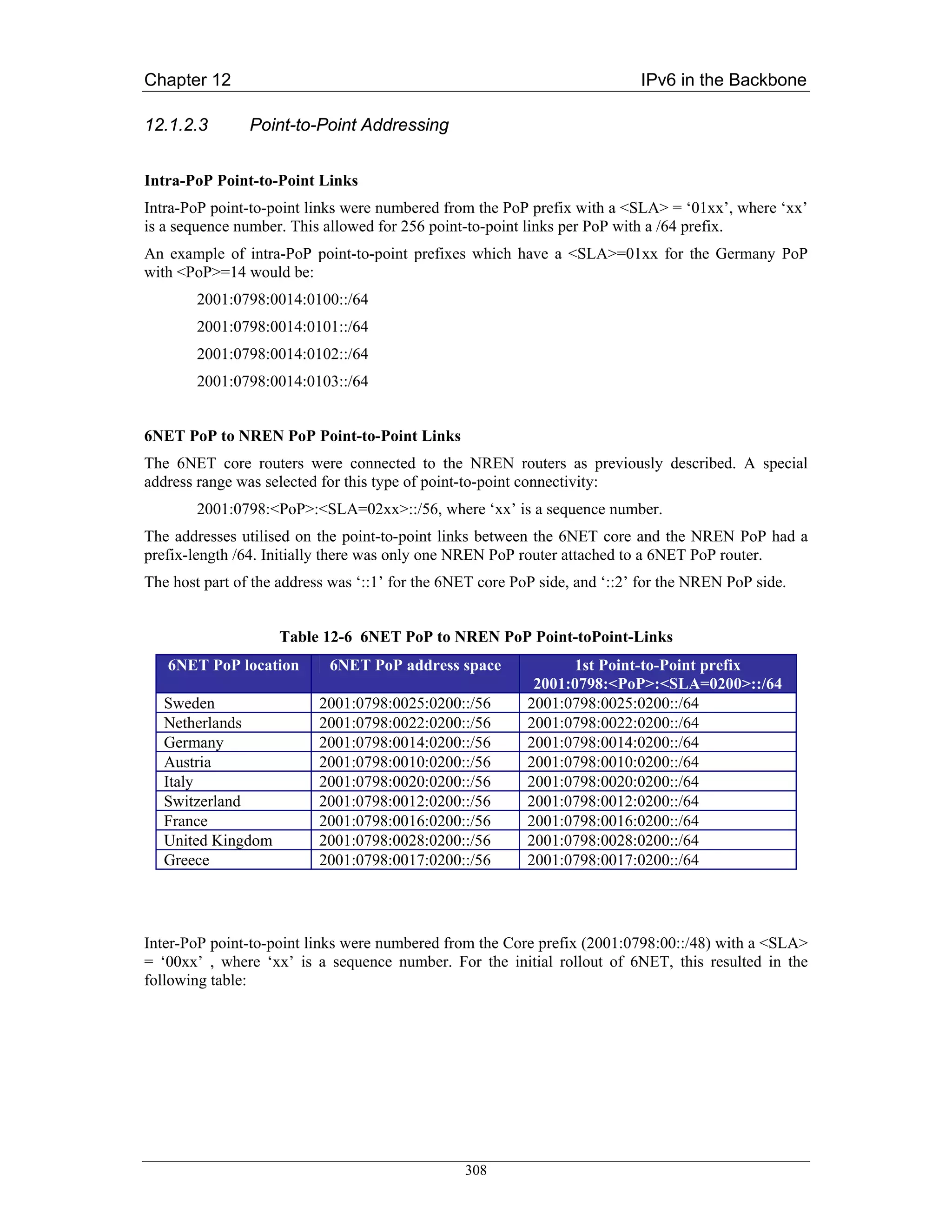
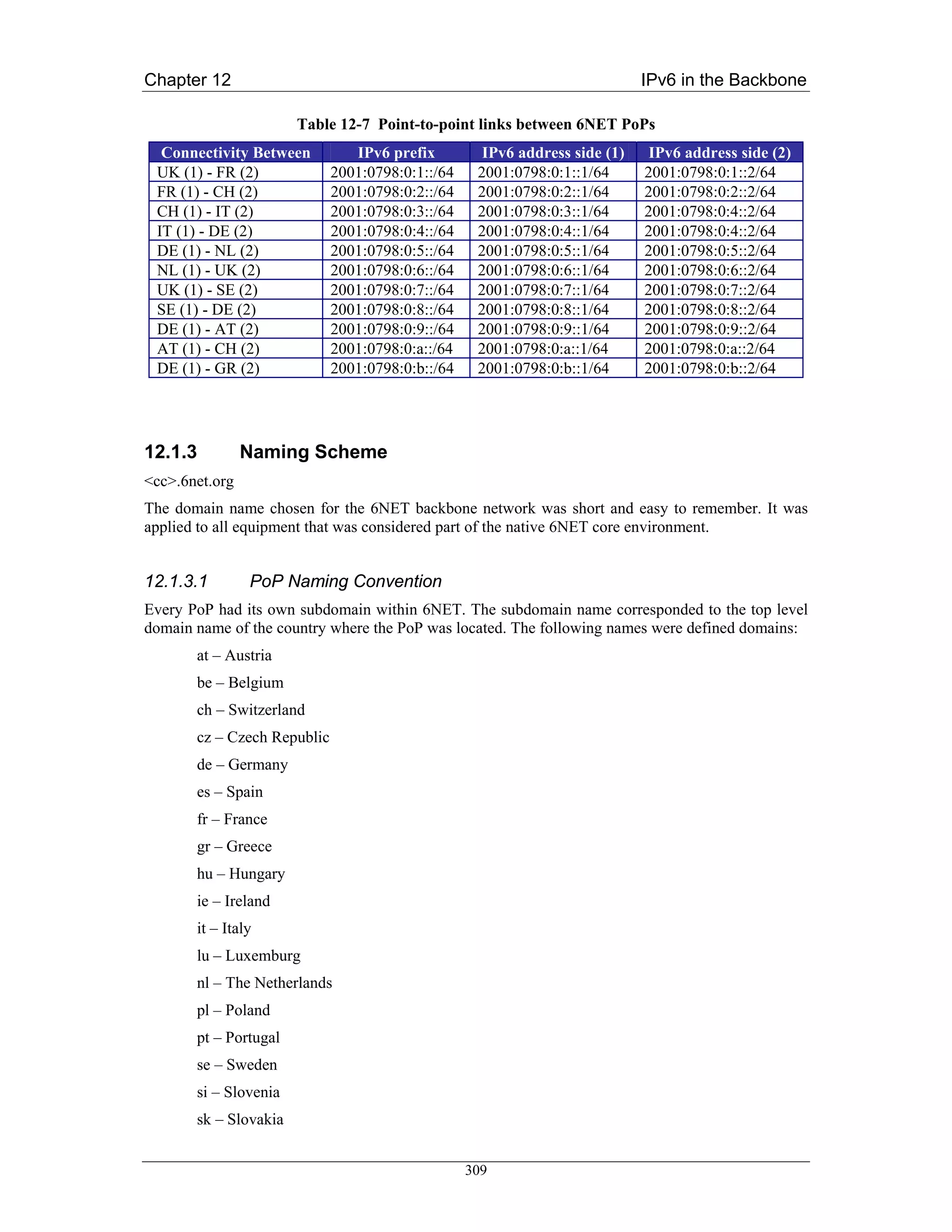
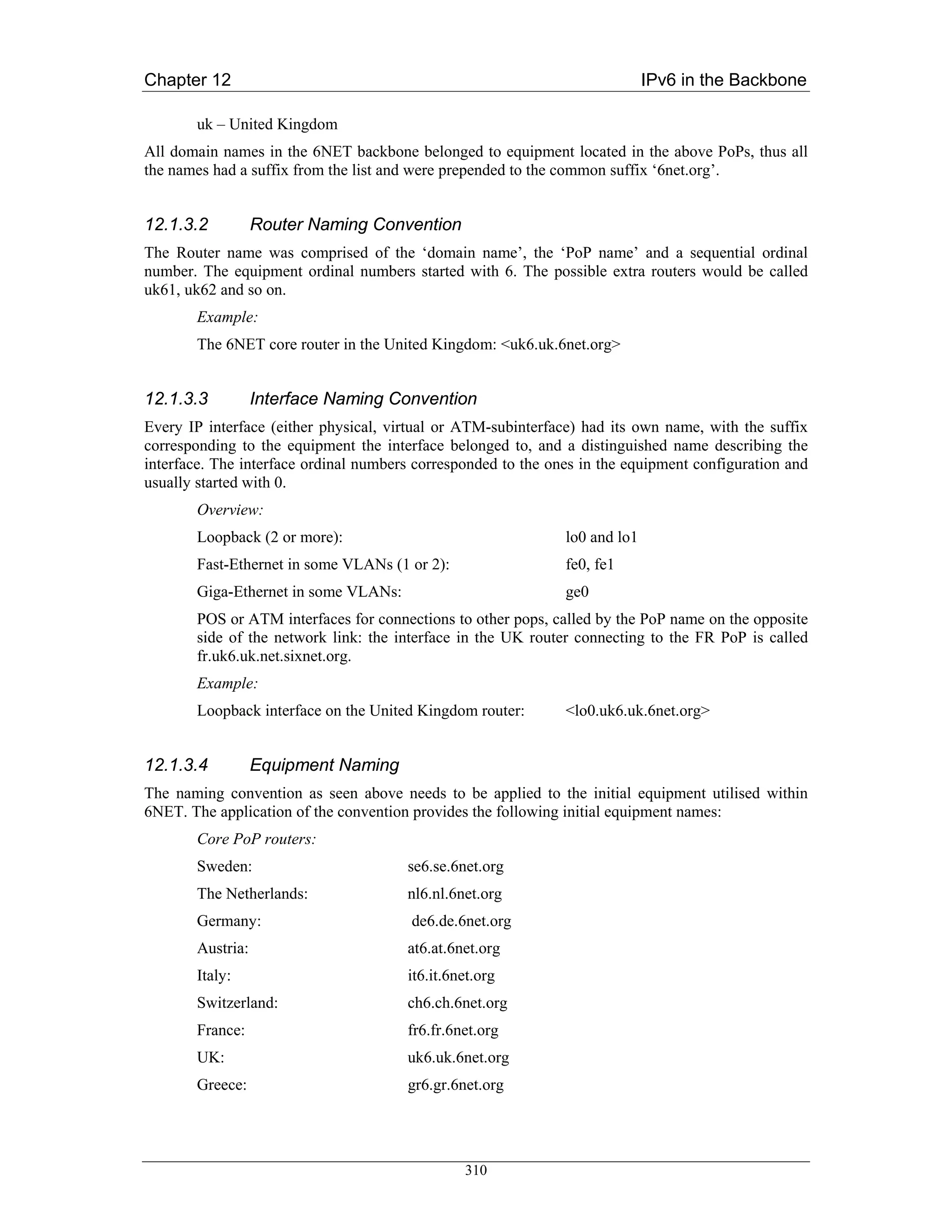
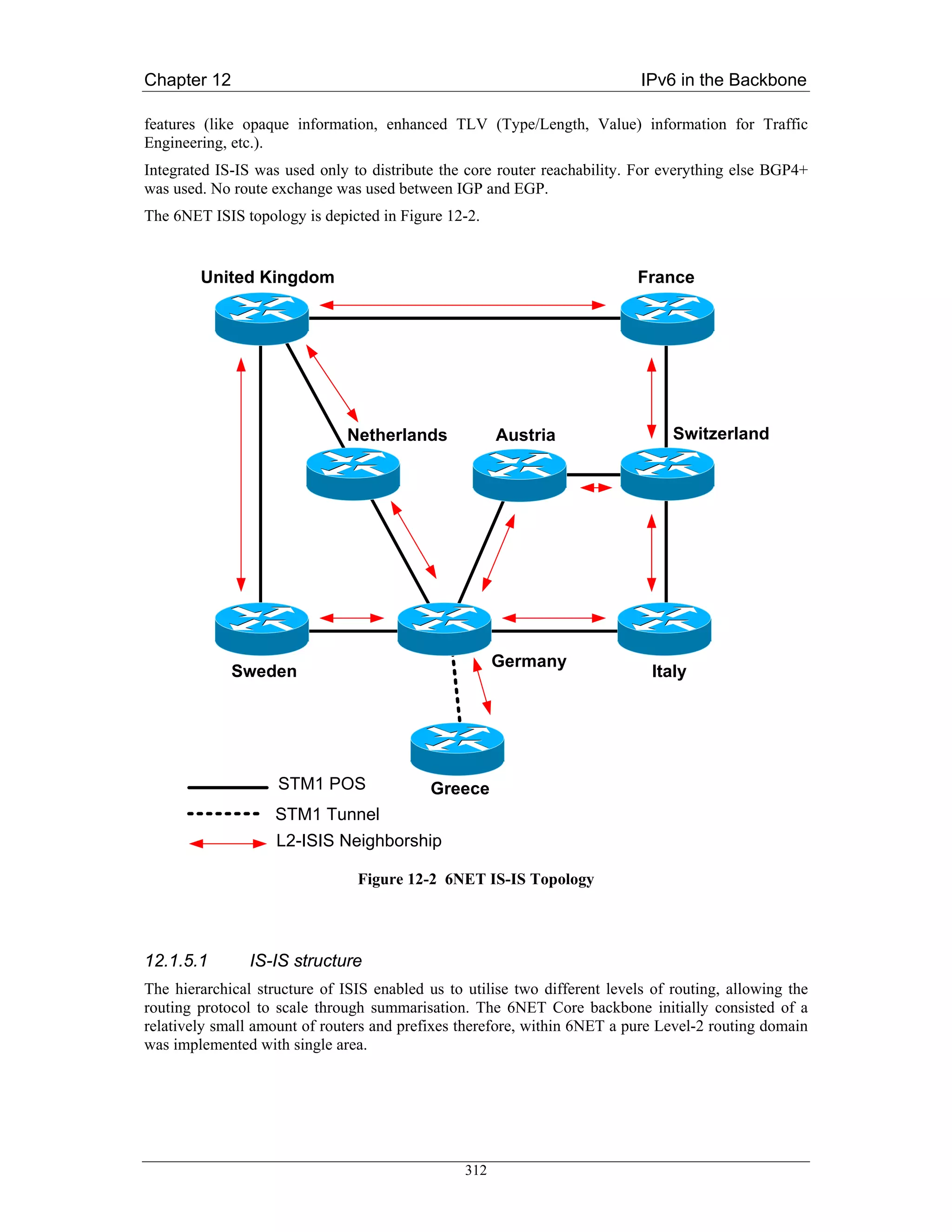
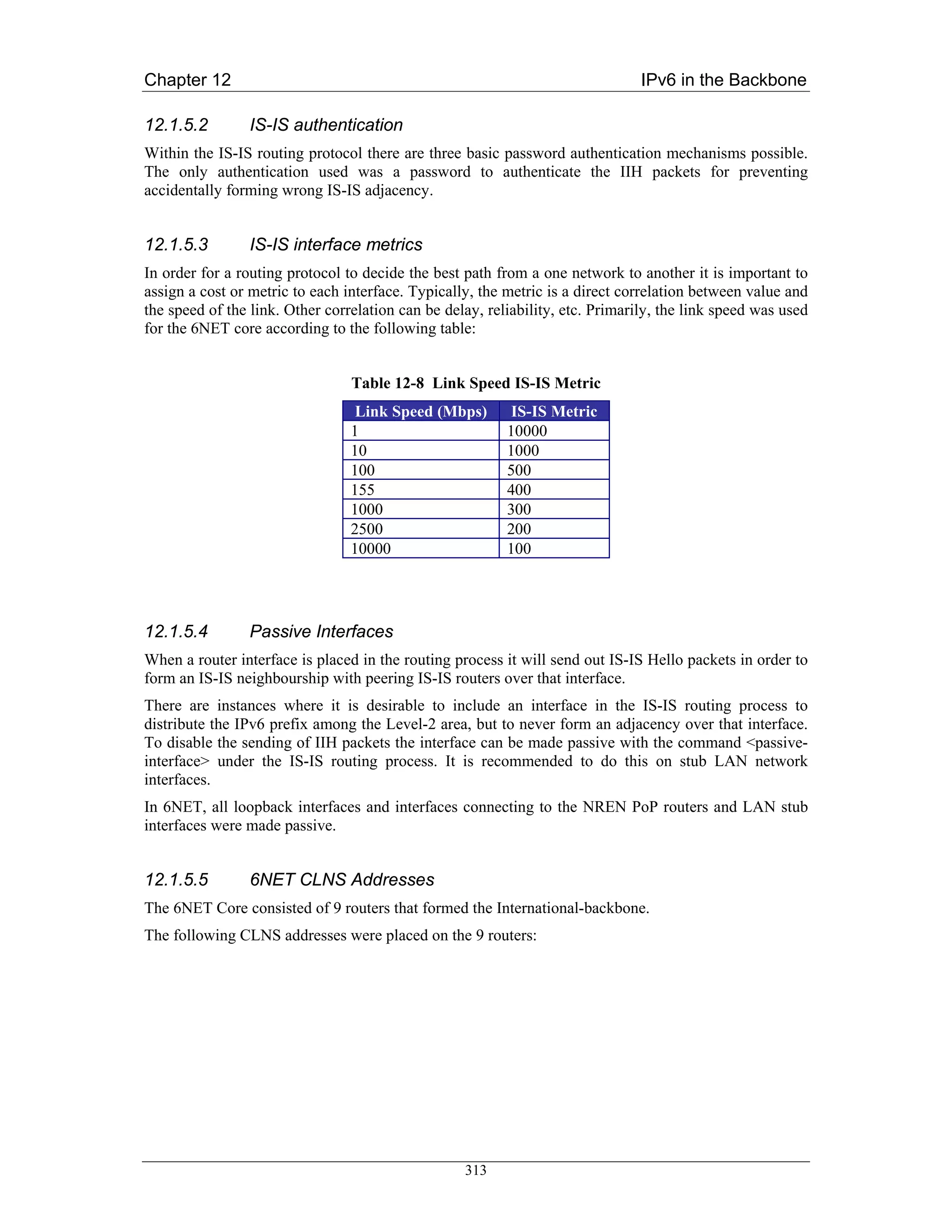
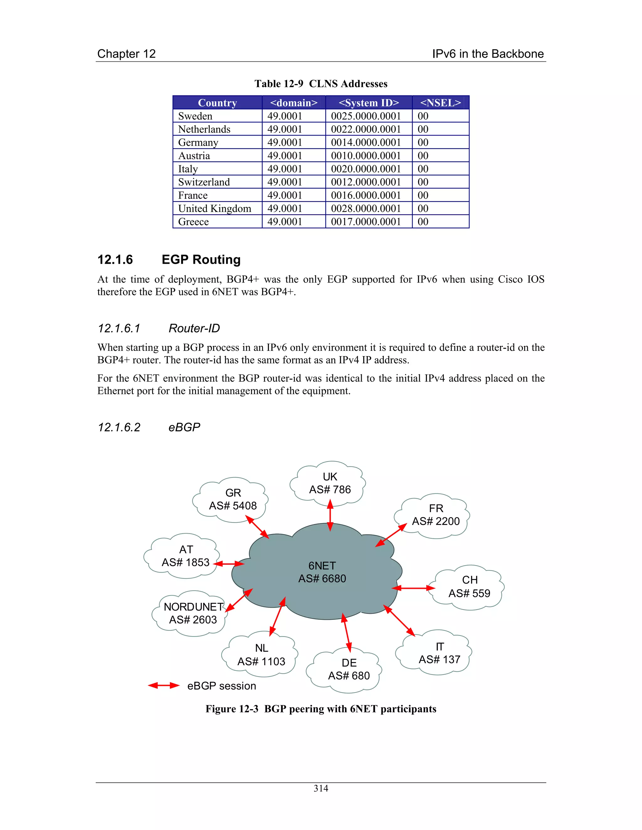
![Chapter 12 IPv6 in the Backbone
BGP4+ was used between 6NET core and participant NRENs, 6NET and other organisations. Each
NREN used their AS numbers. The 6NET core had a separate AS number from GÉANT as can be
seen in Figure 12-3:
Neighbours with the same update policies can be grouped into peer groups to simplify configuration
and to make updating more efficient.
Two initial peer groups were defined:
• Peer group for peerings between 6NET core PoP and NREN PoP:
o 6NET_EXTERNAL_NREN_PEER
• Peer group for peerings between 6NET core PoPs:
o 6NET_INTERNAL_6NET_PEER
12.1.6.3 iBGP
No Route-reflector was used due to the relatively small number of core routers. Instead full mesh BGP
peering was configured inside the core. BGP peerings were secured with TCP MD5 authentication
from the beginning to prevent the wrong peering by accident.
The external peers were grouped together to have same routing policy internally, with the groupname:
6NET_INTERNAL_NREN_PEER
The Next-hop-self functionality was not used in the 6NET rollout. The initial next-hop attribute
checking of the NLRI was based on the IPv6 address from the NREN to which 6NET was peering.
12.1.6.4 BGP filtering
The complete 6NET IPv6 address range could be aggregated to ‘2001:0798::/40’. However, due to the
aggressive filtering policies on the IPv6 Internet (see RFC 2772 [RFC2772]), initially the address
range was aggregated to ‘2001:0798::/35’. To do this type of aggregation in a controllable way, some
NLRI filtering was required. To enable the aggregation, 3 basic steps were required:
1. Configure static IPv6 route for ‘2001:0798::/35’ to the null0 interface
2. Redistribute the static summary route to the IPv6 BGP table (this required NLRI filtering in
order to redistribute only the summary prefix)
3. Use BGP NLRI filtering to the iBGP peers to exclude the summary prefix from being
exchanged.
315](https://image.slidesharecdn.com/ipv6deployment-guide-110112200202-phpapp01/75/IPv6-Deployment-Guide-329-2048.jpg)
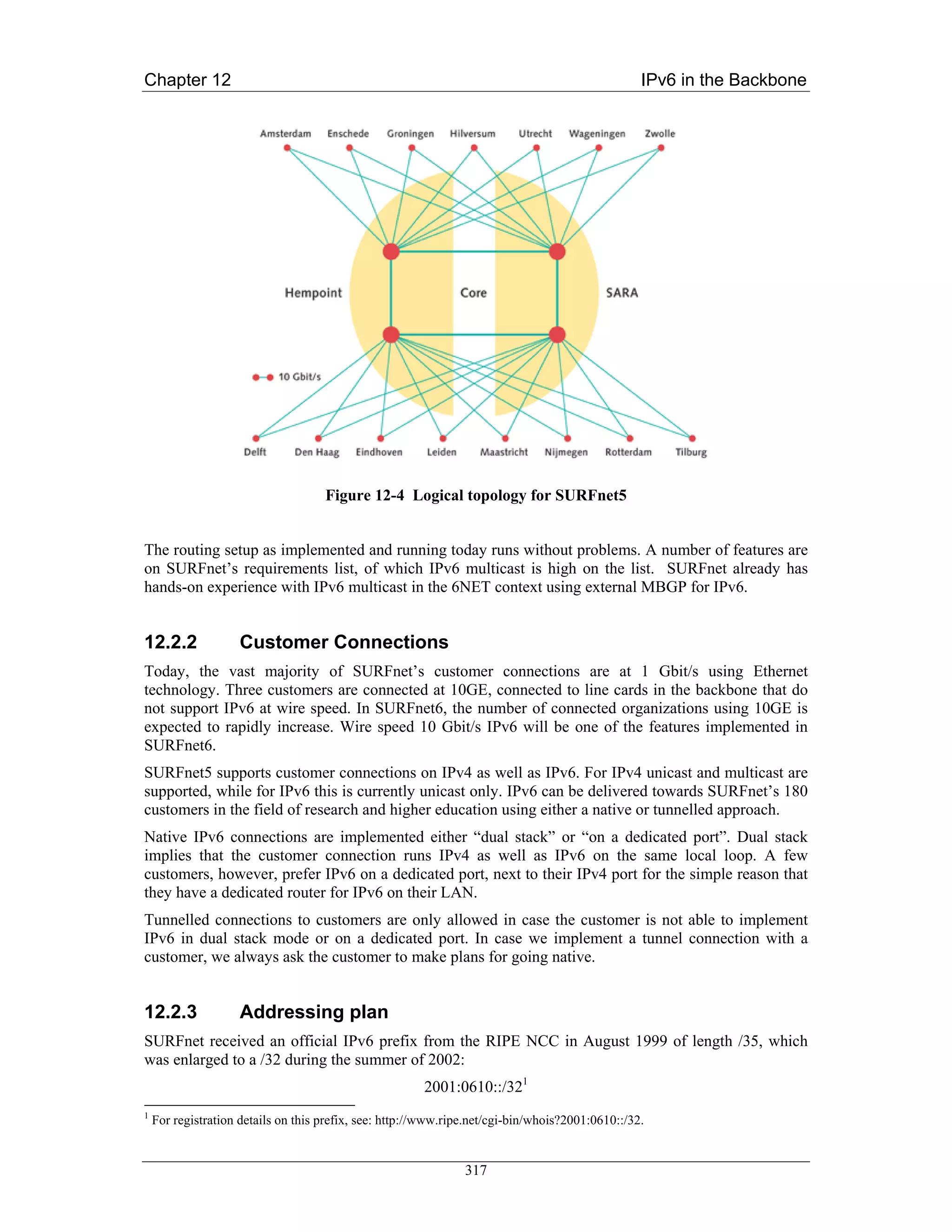
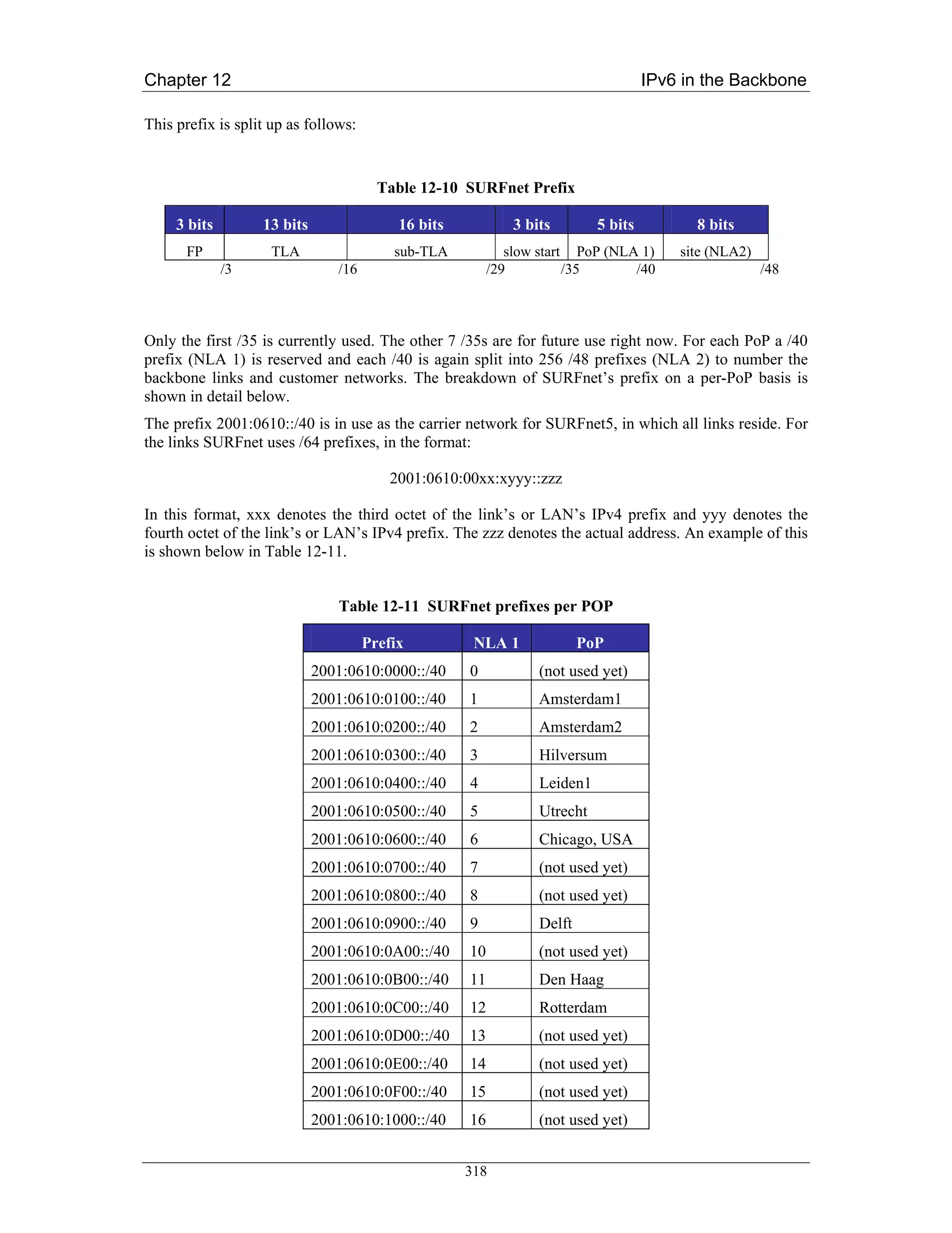
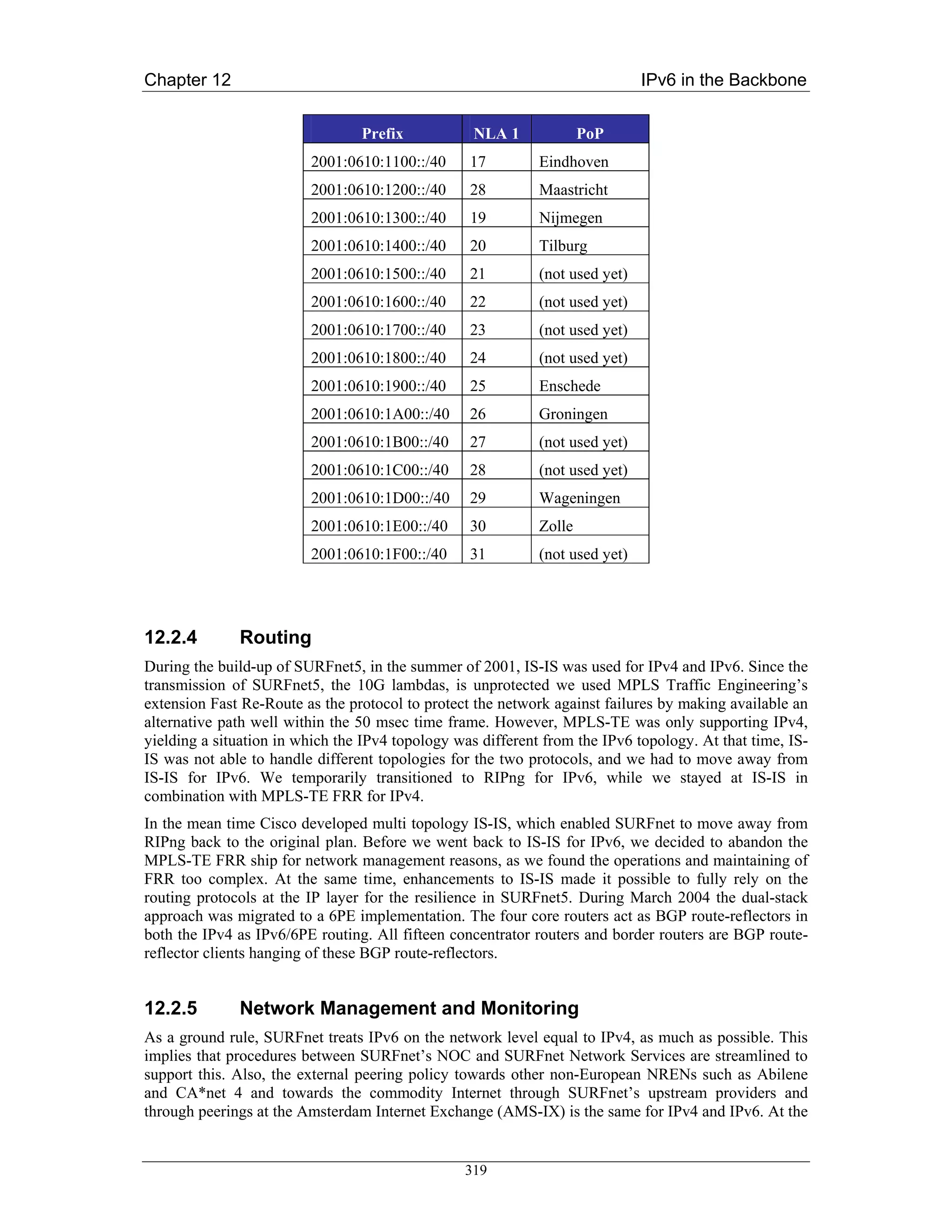
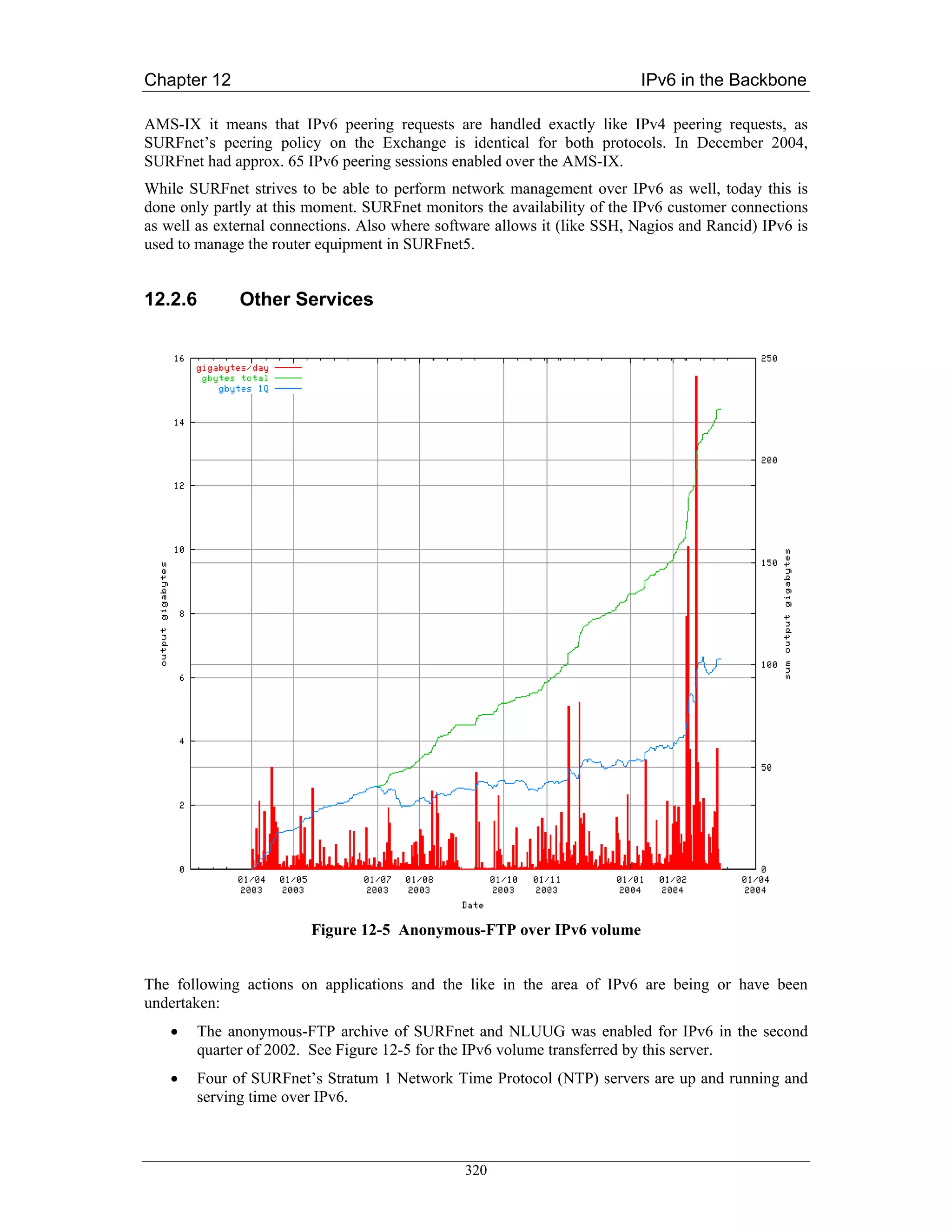
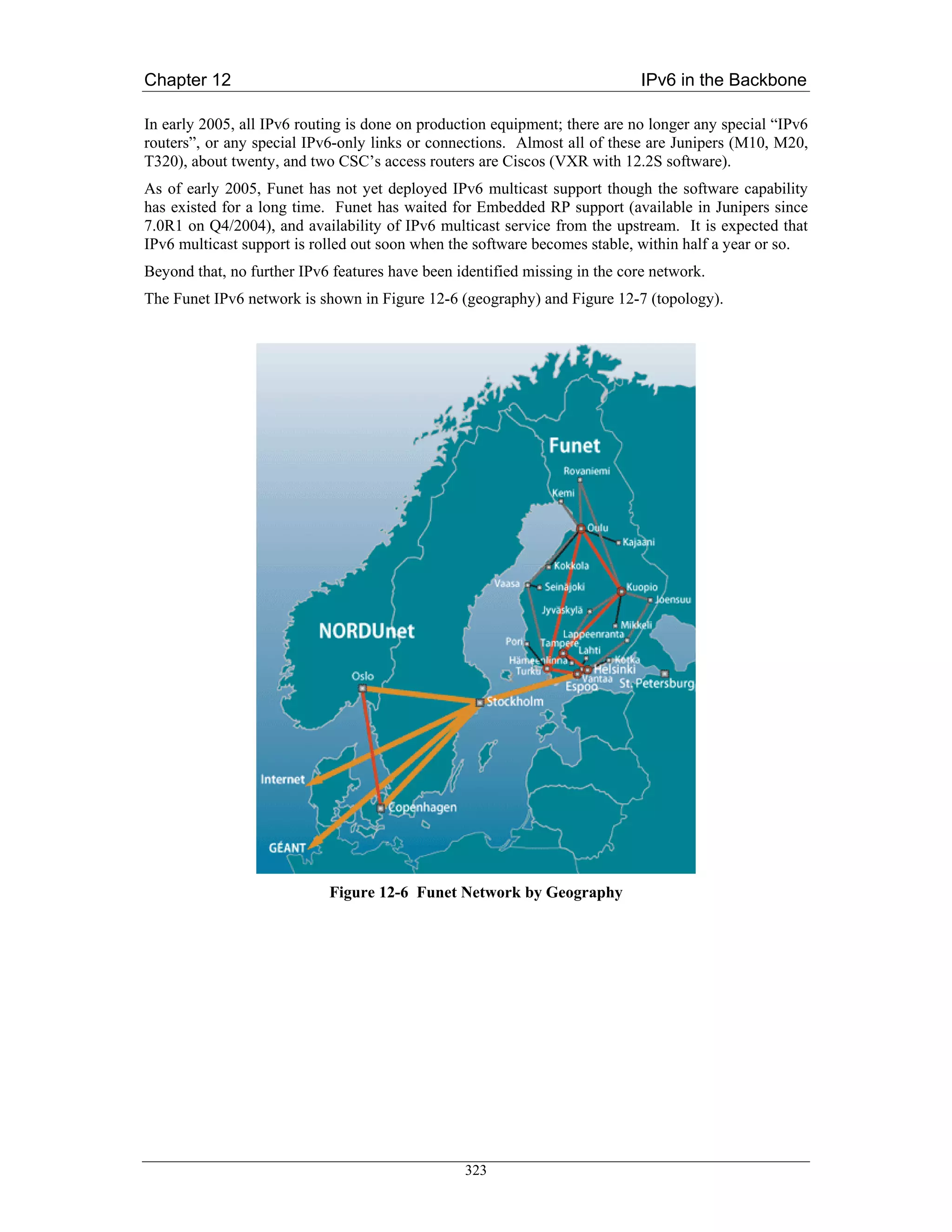
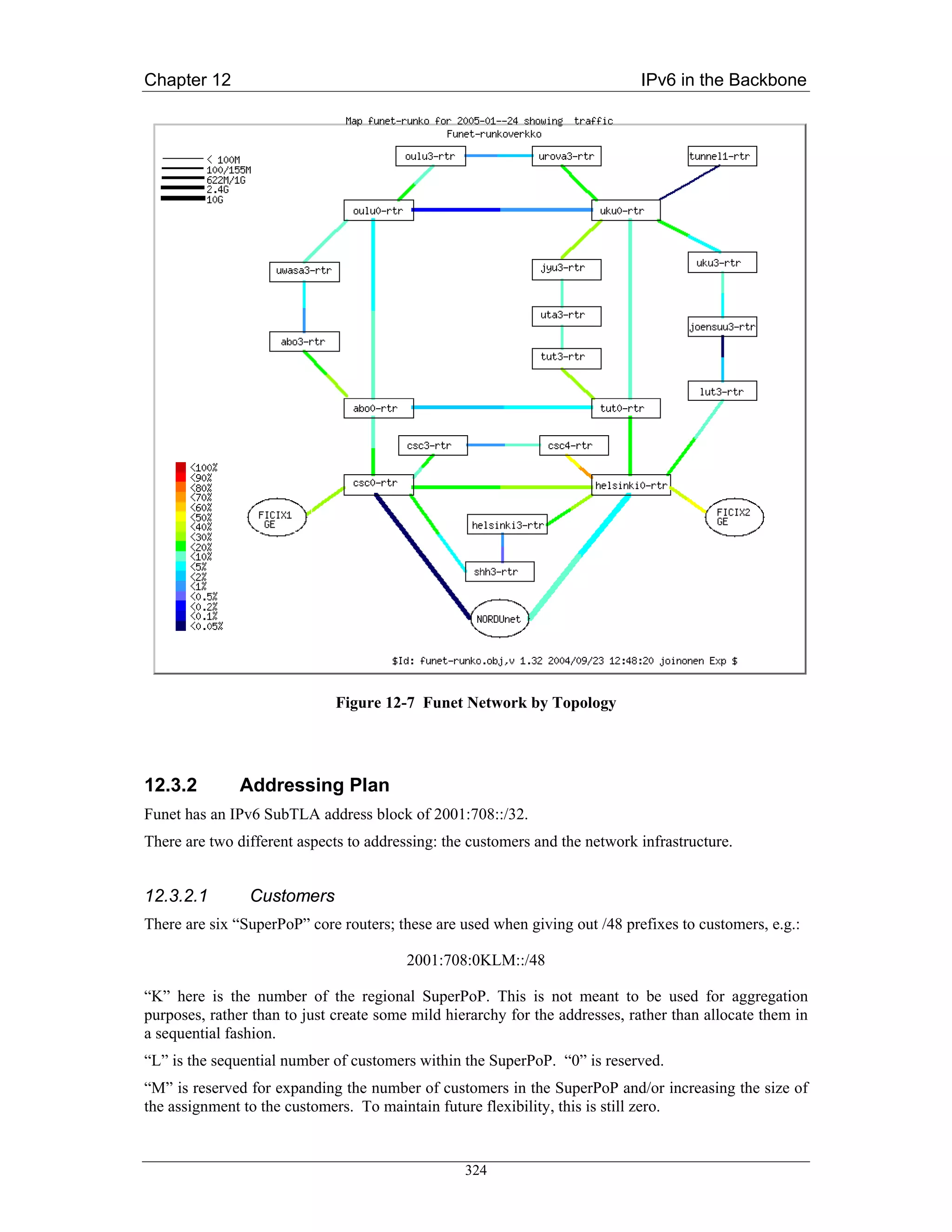
![Chapter 12 IPv6 in the Backbone
When assigning the prefix to the customers, Funet recommends they keep the first four bits (the first
nibble) zero for now.
An example of a customer assignment is 2001:708:510::/48.
12.3.2.2 Network Infrastructure
Here, “KLM” has a slightly different meaning. “K” still means the SuperPoP, “L” means the PoP
acting under the SuperPoP in an access network, and “M” is an identifier for the router in the PoP.
Loopback addresses are taken from the prefix:
2001:708:0:10:KLM::/112
So, a few loopback addresses will be:
tut0-rtr.funet.fi: 2001:708:0:10:300::1
tut1-rtr.funet.fi: 2001:708:0:10:301::1
uta3-rtr.funet.fi: 2001:708:0:10:313::1
These are configured using /128 prefix length. Note that the identifier of the router is also reflected in
the naming (“uta_3_-rtr”).
Point-to-point addresses in the core and the access networks are taken from one block - all addresses
come from under a single /64:
2001:708:0:F000::/64
In particular:
2001:0708:0:F000::klmn:KLMm:z/112
klm and KLM identify the routers at the end of the point-to-point links, taken from the loopback
addresses; in above, these would have been “300”, “301”, and “313”. SuperPoP’s or the smallest
number goes first as klm. “n” and “m” are sequential numbers, used when necessary - for example if
there are multiple links between routers which need to be numbered - defaulting to zero. “z” is the
end-point of the point-to-point link: always “1” or “2”. The same SuperPoP or smallest first rule
applies here too. So, in consequence, the addressing becomes like:
uku0-jyu3: 2001:708:0:F000::4000:3230:[12]/112
uku0-oulu0: 2001:708:0:F000::4000:5000:[12]/112
uta3-jyu3: 2001:708:0:F000::3130:3230:[12]/112
The point-to-point links toward customers are always numbered from the customer’s addresses, due to
simplicity and policy reasons.
For peerings and miscellaneous use, a block of:
2001:708:0:F001::/64
is reserved.
In addition, some special use addresses are used inside 2001:708::/48, for example 2001:708::{1,2}
(for a few routers), 2001:708::123 (NTP), 2001:708::53 (DNS) etc.
12.3.3 Routing
As was already noted, Funet network uses (as of Q1/2005) OSPFv2 for IPv4 and IS-IS (for IPv6 only)
for IPv6. IPv4 infrastructure uses BGP with multiple (private) autonomous systems. Due to the
325](https://image.slidesharecdn.com/ipv6deployment-guide-110112200202-phpapp01/75/IPv6-Deployment-Guide-339-2048.jpg)
![Chapter 12 IPv6 in the Backbone
(relatively) low number of IPv6 customers and traffic, the same kind of BGP topology has not been
built for IPv6. Instead, IPv6 BGP has only been set up at the border routers, and the rest use IS-IS.
A longer term idea has been to switch from OSPFv2 to using IS-IS for both IPv4 and IPv6, but this
has been a low priority task, and as of this writing, has not been done yet. At the same time, the same
kind of BGP topology would probably be built.
12.3.4 Configuration Details
In this section, core and customer (edge) configuration examples are listed.
12.3.4.1 Configuring the Core
The configuration of the Juniper routers is given below.
interfaces {
lo0 {
unit 0 {
family iso {
address 49.0001.1931.6600.5180.00; "IS-IS address from IPv4"
}
family inet6 {
address 2001:708:0:BB:eeee:ffff:0000:1111/128; "Loopback"
}
family inet {
[...]
}
}
}
so-X/X/X {
unit 0 {
[...]
family iso; "For IS-IS"
family inet6 {
address 2001:708:0:BB:aaaa:bbbb:cccc:dddd/112; "Core"
}
family inet {
[...]
}
}
}
}
protocols {
326](https://image.slidesharecdn.com/ipv6deployment-guide-110112200202-phpapp01/75/IPv6-Deployment-Guide-340-2048.jpg)
![Chapter 12 IPv6 in the Backbone
isis {
no-ipv4-routing;
export ipv6-to-isis;
level 1 disable;
interface so-X/X/X.0 { "Core connections"
level 2 metric 2;
}
interface lo0.0 {
passive;
}
}
}
policy-options {
policy-statement ipv6-to-isis {
from {
protocol [ direct local static isis ];
family inet6;
}
then {
accept;
}
}
}
And respectively on Cisco:
interface POSX/Y
[...]
ipv6 address 2001:708:0:BB:aaaa:bbbb:cccc:dddd/112
ipv6 router isis
isis circuit-type level-2-only
isis metric 2
!
router isis
passive-interface Loopback0
!
address-family ipv6
redistribute static
redistribute connected
no adjacency-check
exit-address-family
327](https://image.slidesharecdn.com/ipv6deployment-guide-110112200202-phpapp01/75/IPv6-Deployment-Guide-341-2048.jpg)
![Chapter 12 IPv6 in the Backbone
is-type level-2-only
net 49.0001.1931.6600.5181.00
metric-style transition
log-adjacency-changes
!
As can be seen, the model is such that all the routes of the router are redistributed in the IS-IS. An
alternative approach would be to include all the interfaces in the IS-IS as passive interfaces.
This is not considered to have serious drawbacks, as none of these redistributed routes are advertised
outside the autonomous system: the advertisement includes the aggregates only.
12.3.4.2 Connecting the Customers (edge)
Customers are connected using static routes. The configuration is very simple, like the below on
Juniper:
interfaces {
fe-X/X/X {
unit Y {
[...]
family inet6 {
rpf-check fail-filter RPF_FAIL_IPV6;
address 2001:708:KLM:xxxx::2/64; # from the customer
}
}
}
}
routing-options {
rib inet6.0 {
static {
route 2001:708:KLM::/48 next-hop 2001:708:KLM:xxxx::1;
}
}
}
firewall {
family inet6 {
filter RPF_FAIL_IPV6 {
term DEFAULT {
then {
count count-rpf-fail-ipv6;
log;
discard;
}
328](https://image.slidesharecdn.com/ipv6deployment-guide-110112200202-phpapp01/75/IPv6-Deployment-Guide-342-2048.jpg)
![Chapter 12 IPv6 in the Backbone
}
}
}
}
And on Cisco this could look like:
interface Fa0/0
[...]
ipv6 address 2001:708:KLM:xxxx::2/64
!
ipv6 route 2001:708:KLM::/48 2001:708:KLM:xxxx::1
12.3.5 Monitoring
The addresses of all loopback and point-to-point addresses are entered into DNS in a special format.
A script configured to allow zone-transfer of “ipv6.funet.fi” zone fetches this information and digs out
the IP addresses which should be in use. The pinger periodically (once in five minutes) checks that
the links (including the links to customers and the peers) are up and responding; if not, it sends an
alert.
BGP and IS-IS adjacencies are also monitored using a tool which collects syslog warnings sent from
routers to a central syslog server. If adjacencies or sessions flap, this can be noted in the monitoring
page.
All routers and links are collected to a custom network map/monitoring tool, where the traffic levels
and similar can be monitored easily.
A challenge in the dual-stack infrastructure is getting a feel how much traffic on the links is IPv4 and
how much IPv6. As of this writing, there are no good mechanisms to get that. When IPv6 MIBs are
complete and are implemented, getting such measurements may be easier.
The performance has not been rigorously tested, as the Junipers include a hardware IPv6 forwarding
capability. When Cisco’s performance issues were noticed, and CEFv6 was tested, Funet also briefly
tested the backbone network’s IPv6 forwarding capabilities; a PC with Gigabit Ethernet interface
could not send enough traffic to cause any impact on the network, which was indeed what was
expected.
12.3.6 Other Services
Funet has been using and advertising a 6to4 relay to everywhere (openly) since late 2001. This
includes the advertisement of 2002::/16 and 192.88.99.0/24. The router in question is a FreeBSD
system running zebra OSPF and BGP routing protocols.
IPv6 multicast has also been tested using separate infrastructure and tunnels, but this has been shut
down as of Q1/2005, pending the upgrade of the core network to support IPv6 multicast.
A TCP/UDP relay (faith in FreeBSD) is used on server-side to experimentally enable IPv6 access to a
few IPv4-only services.
An IPv6 newsfeed service is IPv6-enabled, and is generating 30+ Mbit/s of steady IPv6 traffic. Also,
ftp.ipv6.funet.fi is also IPv6-operational.
329](https://image.slidesharecdn.com/ipv6deployment-guide-110112200202-phpapp01/75/IPv6-Deployment-Guide-343-2048.jpg)

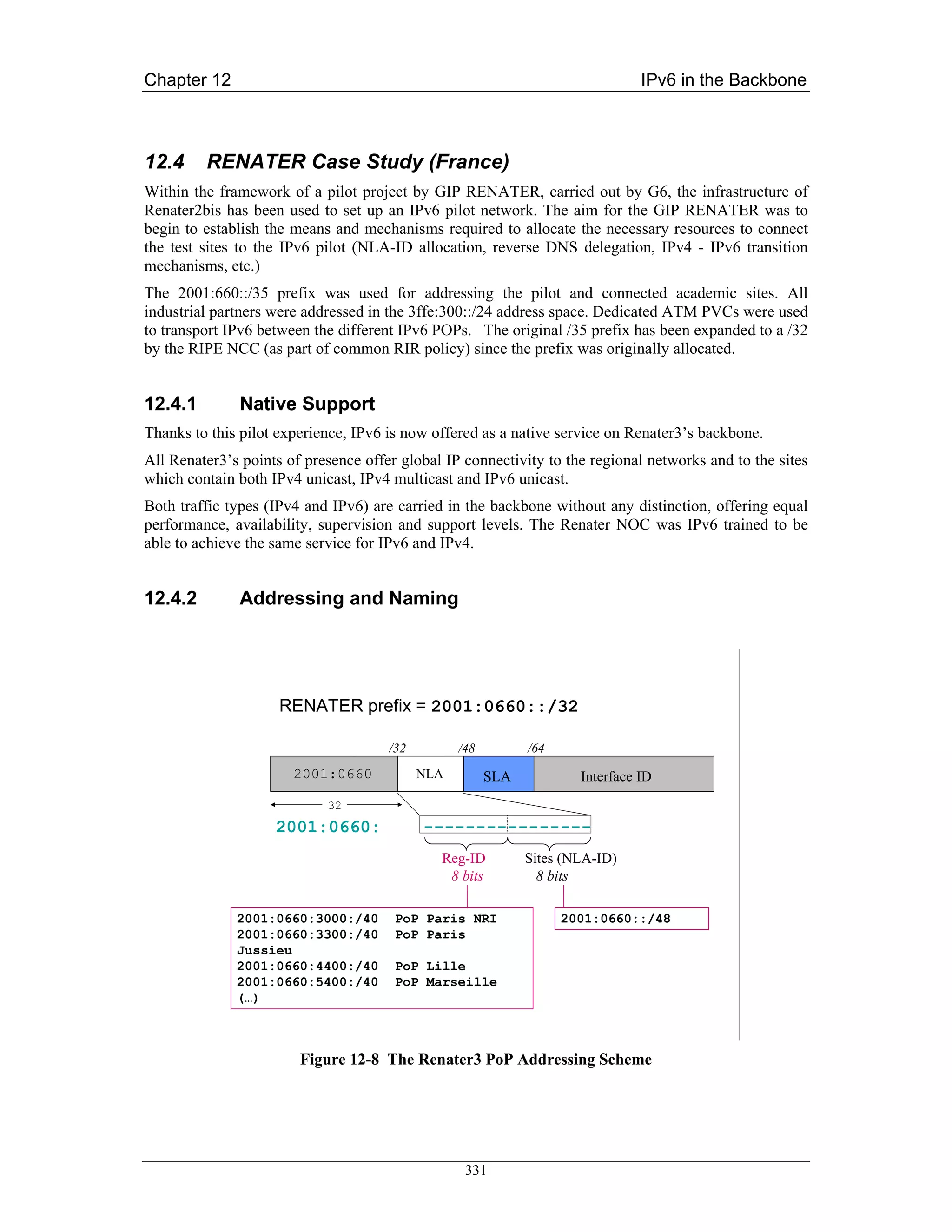
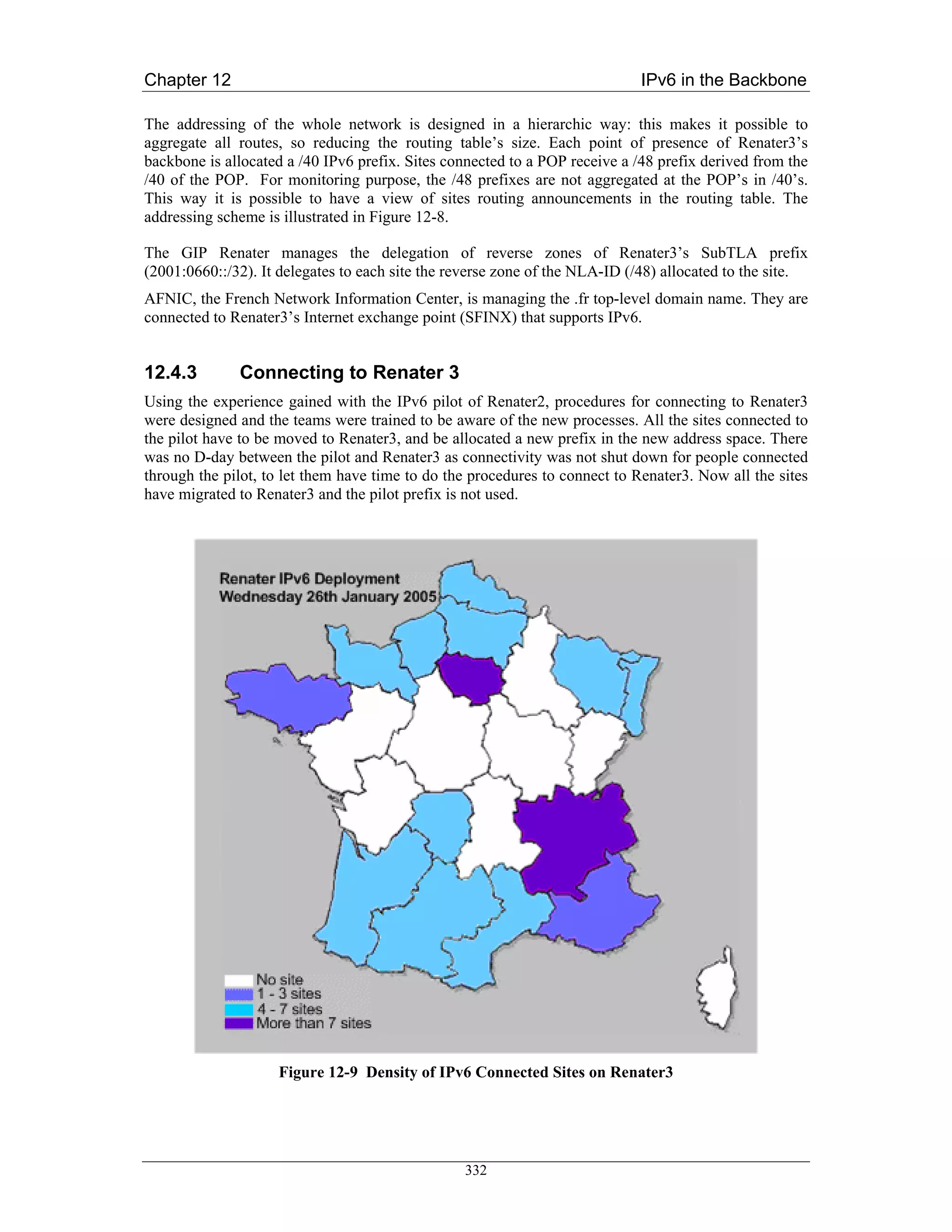
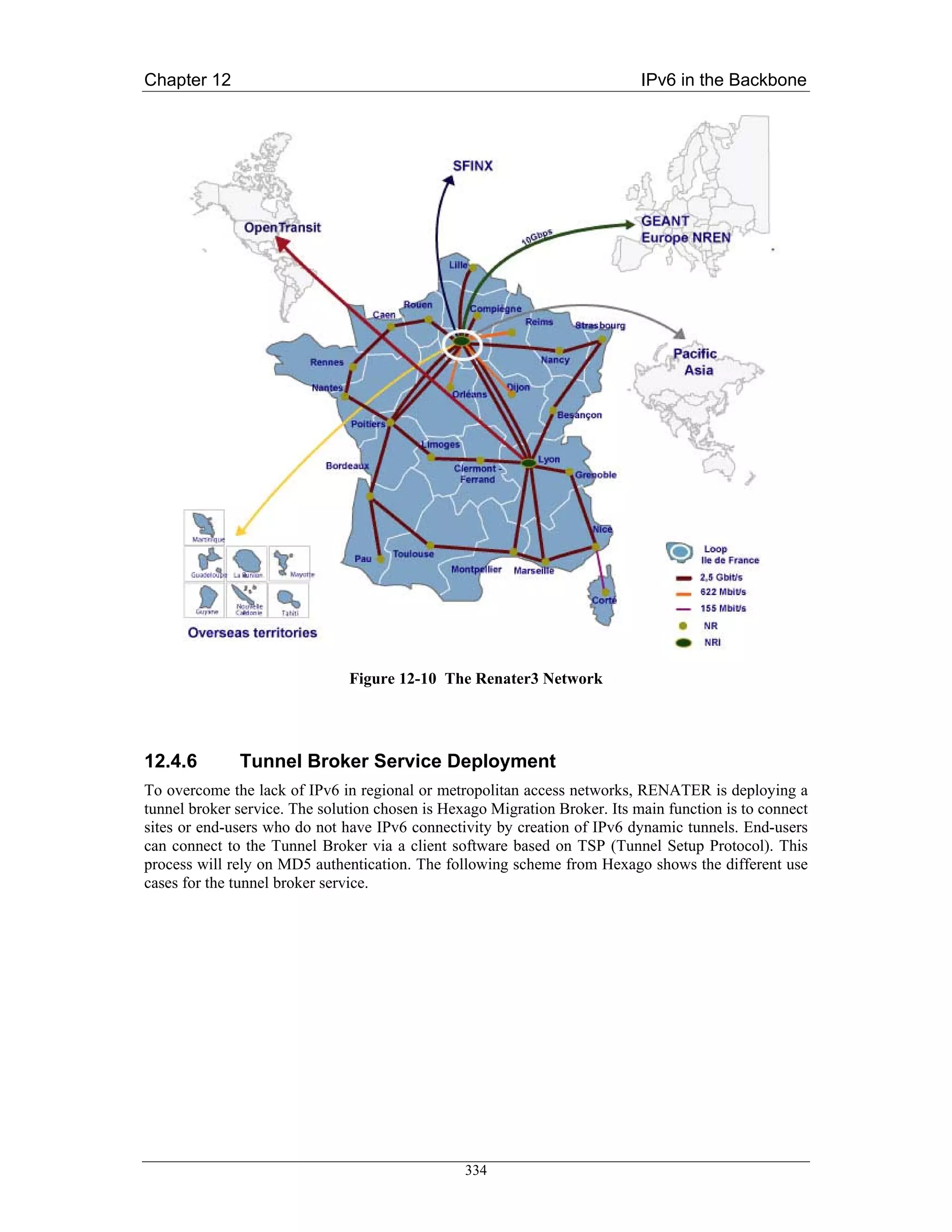
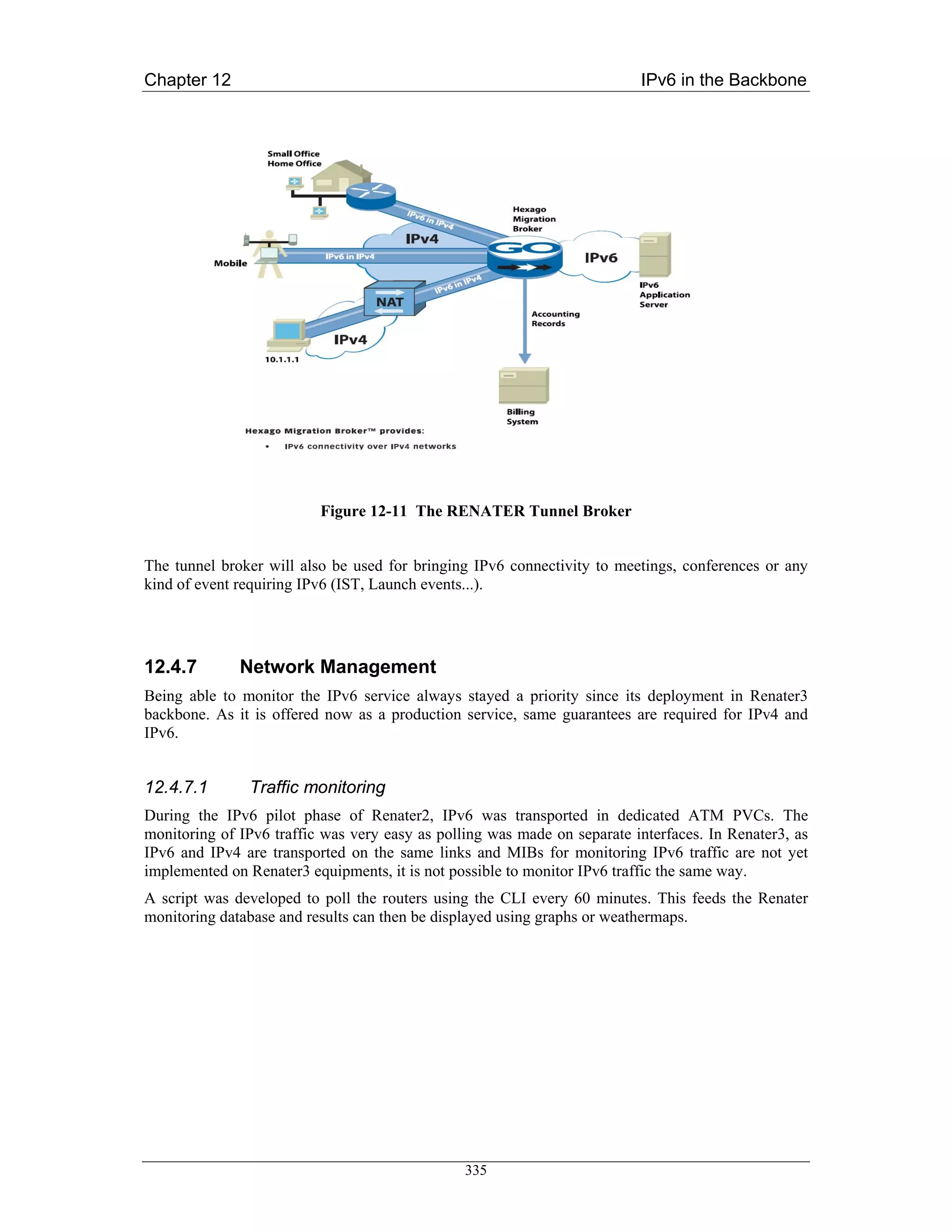
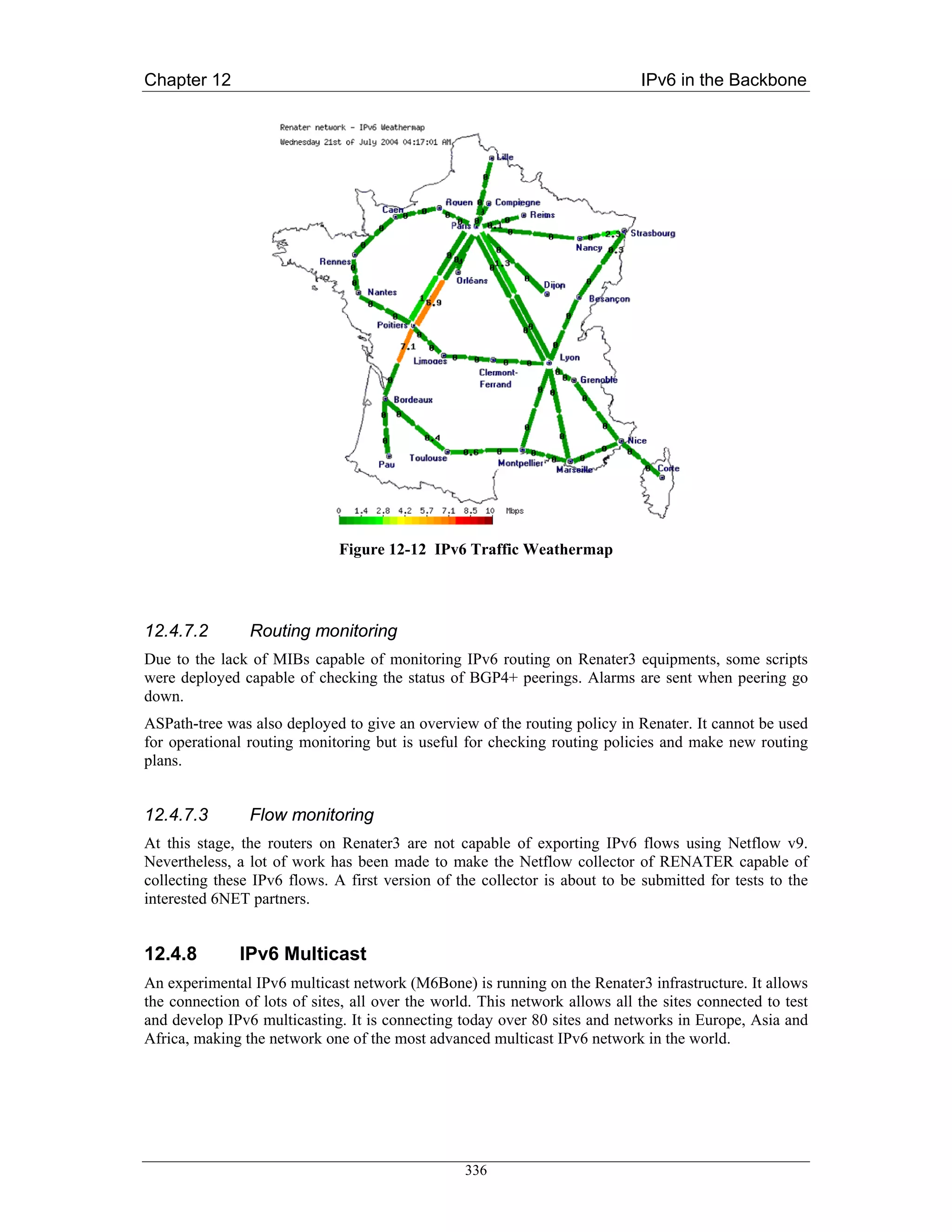
![Chapter 12 IPv6 in the Backbone
12.5 SEEREN Case Study (GRNET)
The South East European Research and Education Networking (SEEREN) infrastructure interconnects
the Research and Education Networks (NRENs) of Albania, Bosnia-Herzegovina, Bulgaria, FYR of
Macedonia, Greece, Hungary, Romania and Serbia-Montenegro amongst themselves and to the
European backbone network. In this respect, it constitutes the South-Eastern European segment of the
multi-gigabit pan-European Research and Education network, GÉANT.
The SEEREN infrastructure was officially inaugurated in January 2004, with first IPv4 services
provided in November 2003. Since then, the project has been developing several services and tools on
top of the infrastructure, including a virtual network operations centre and a one-stop-shop for the
management tools [SEEREN]. The deployment of IPv6 services has been planned since Spring 2004.
12.5.1 SEEREN Network
The SEEREN physical and logical network topologies are depicted in Figure 12-13 and Figure 12-14,
respectively. The MPLS-enabled core network infrastructure, which is provided by a consortium of
operators in SE Europe, has Points of Presence (PoPs) in all the SE European capital cities.
Interconnection between the SEEREN NRENs is achieved with the Carrier supporting Carrier (CsC)
technique (see Figure 12-15), which enables an MPLS VPN-based service provider, called the carrier
provider, to allow other IP (or MPLS) service providers, called customers carriers (SEEREN
NRENs1), to use a segment of its backbone network.
Figure 12-13 SEEREN Physical Network Topology
The access links of SEEREN NRENs range from 2Mbps up to 34Mbps, while connectivity is achieved
by using diverse technologies from ATM to Ethernet over PPP (EoPPP). The SEEREN primary
connection to GÉANT is a 95Mbps ATM PVC crossing GRNET. A secondary (backup) 34Mbps
1
Each SEEREN NREN has deployed and manages one border router for its international connectivity. These routers consist
of a “virtual” customer provider network.
337](https://image.slidesharecdn.com/ipv6deployment-guide-110112200202-phpapp01/75/IPv6-Deployment-Guide-351-2048.jpg)
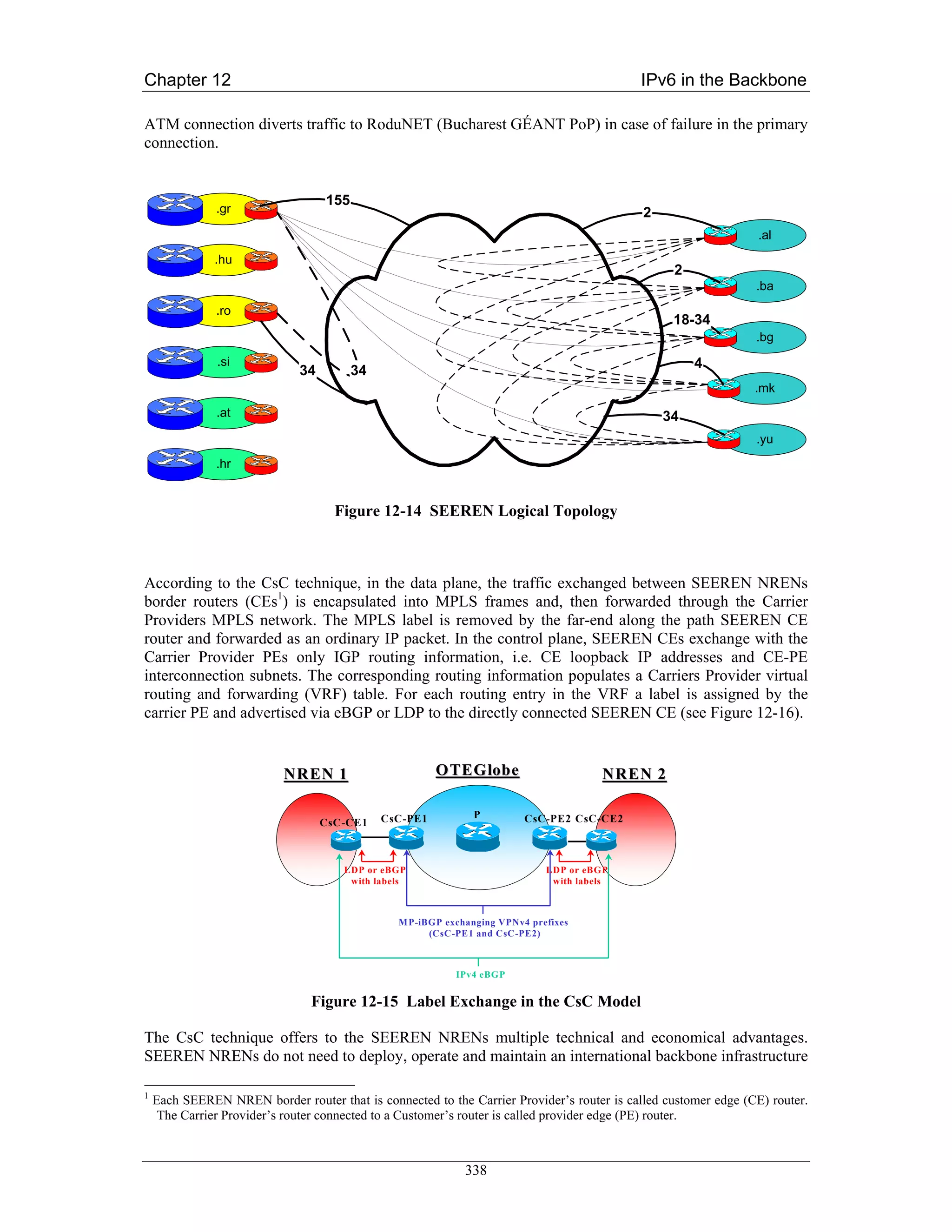
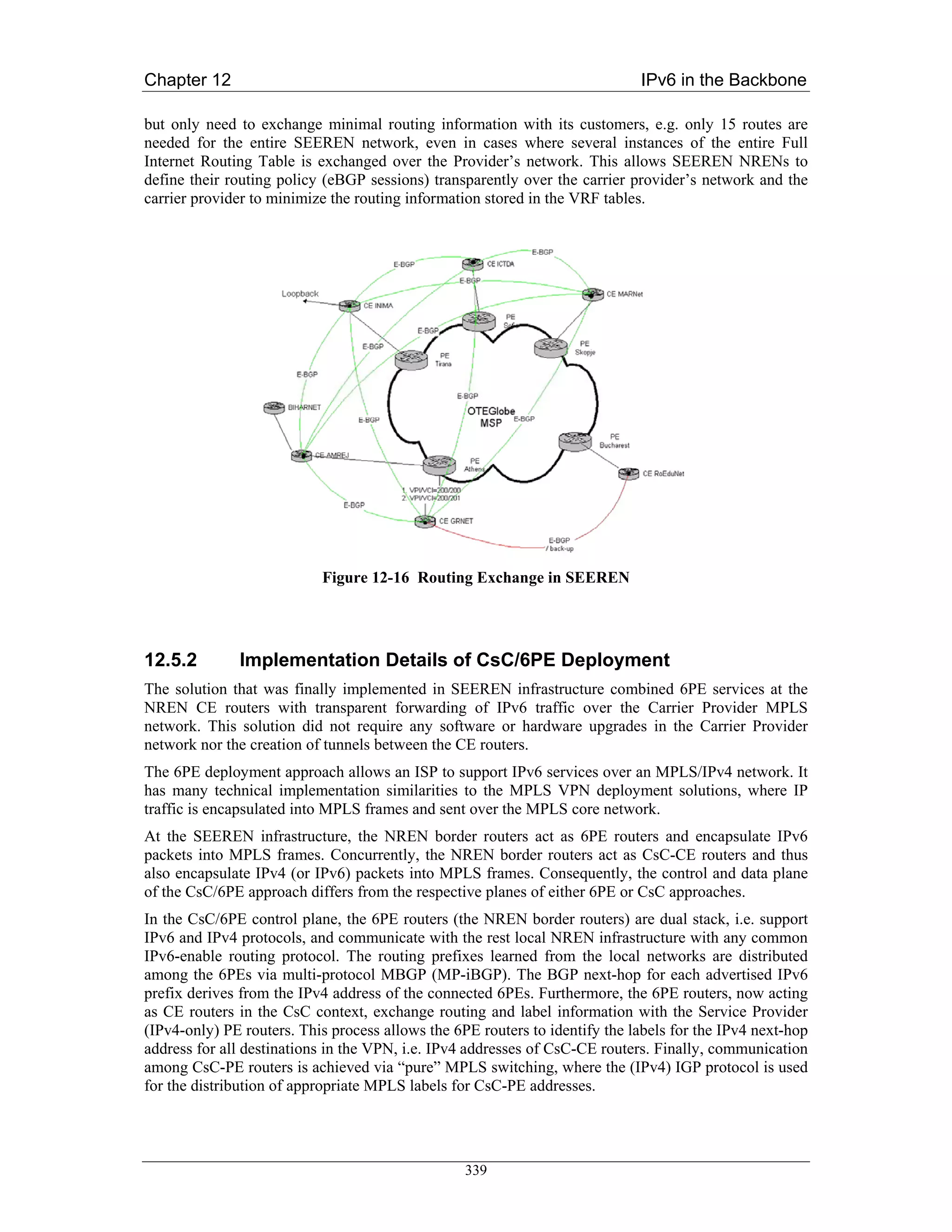
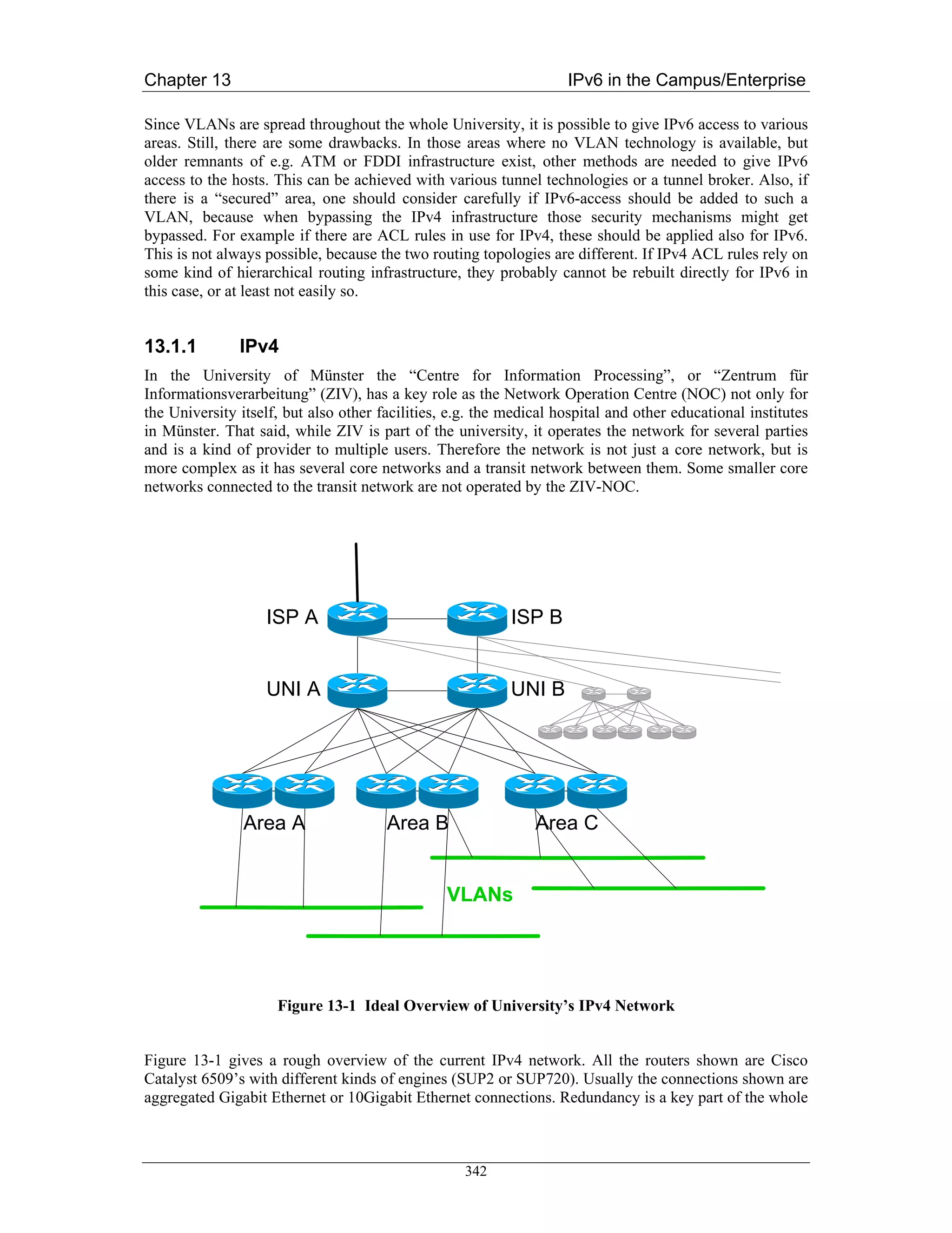
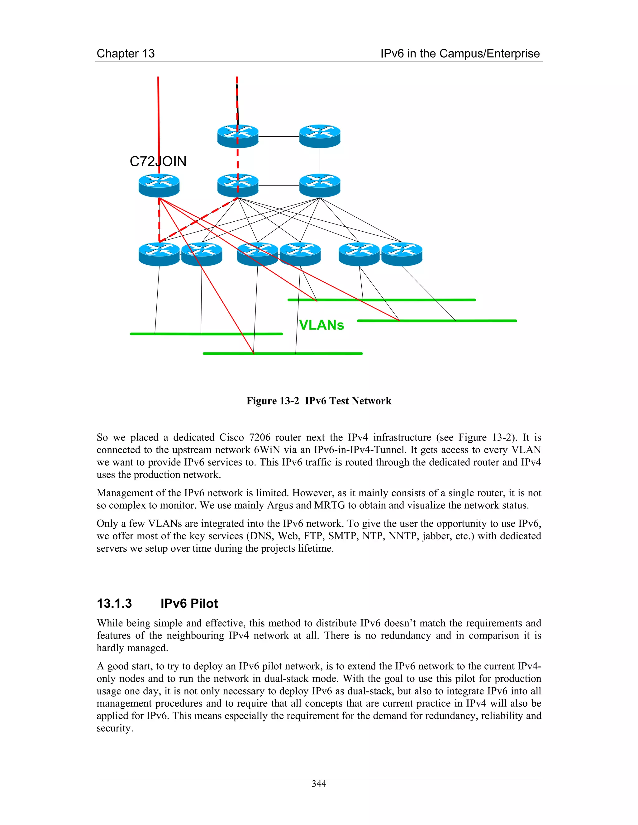
![Chapter 13 IPv6 in the Campus/Enterprise
Usage of SubnetID
As recommended for any enterprise site, the University of Münster received a /48 prefix from its
provider DFN. We discussed a lot how to use the available address space and the SubnetID with the
technical personnel of ZIV-NOC, based on our own discussion paper.
We came to the conclusion that a single /48 prefix is insufficient for our needs. There are multiple
reasons. In the first place our University is very large and has ten thousands of students and personnel.
Then the ZIV is not only giving connectivity to the University but is also managing the network and is
giving broadband access to other parties, like the medical facilities and e.g. the Fachhochschule.
Thus ZIV-NOC is more a provider than just a University’s NOC. Finally ZIV-NOC offers all students
and personnel Internet access via ISDN. Following the rules in RFC 3177 [RFC3177] we should
allocate a /48 to most of these users. With more than 50,000 students we would need more than a /32
prefix to achieve this. Something similar applies for VPN customers using the IPv6 tunnel broker
system.
We tried to obtain more address space from our provider DFN. After lengthy discussions with DFN
and RIPE, DFN was not able to fulfil our needs. The solution was to become a RIPE member, an LIR,
and apply for our own /32 prefix. This way we would be allocated enough address space and
additionally solve any multihoming issues, by having what amounts to Provider Independent (PI) IPv6
address space (we would be the provider).
At the time of writing, we have become RIPE members, but haven’t been allocated a prefix so far.
Therefore we will use the standard IPv6 documentary prefix 2001:db8::/32 (see RFC 3849
[RFC3849]) for examples in this section.
Usage of the provider /32 prefix
We split the 16 bit provider address range from bit 33 to 48 into four large chunks and defined a
Format Prefix (FP) for each address range:
< 2 bits Format Prefix >< 14 bits free for use >
The Format Prefix is used in this way:
FP 00: 2001:db8:0000::/48 - 2001:db8:3fff::/48: Standard broadband customer allocations
FP 01: 2001:db8:4000::/48 - 2001:db8:7fff::/48: VPN access, e.g. OpenVPN tunnelbroker
system
FP 10: 2001:db8:8000::/48 - 2001:db8:bfff::/48: Remote Access Service (RAS), e.g. ISDN
dial-in customers
FP 11: 2001:db8:c000::/48 - 2001:db8:ffff::/48: Reservation for RAS or other
Usage of the last three blocks is hopefully very simple. Except for the first block, prefixes will become
allocated consecutively starting with Zero (of each block). Currently we have about 8,000 RAS
customers and about 15 OpenVPN tunnel broker customers. While the amount of RAS customers rises
slowly, we expect a significant increase in the OpenVPN tunnel broker customers, once the tunnel
broker system is integrated in the management plane of ZIV-NOC and we are able to give production
IPv6 access via that system. The FP 11 block can be used for further RAS users if the FP 10 is ever
exceeded or for any other usage if it arises. The only Format Prefix block that needs further
subdividing is FP 00.
At least the addressing plan of the University’s /48 prefix is very tight and it is highly likely that it will
be exhausted at some point in time in the future. So instead of addressing consecutively like in the
other three Format Prefix blocks, making reservations makes sense. Instead of making sparse
reservations we choose to be generous here, as we do not expect to see that many broadband users for
348](https://image.slidesharecdn.com/ipv6deployment-guide-110112200202-phpapp01/75/IPv6-Deployment-Guide-362-2048.jpg)

![Chapter 13 IPv6 in the Campus/Enterprise
13.2 Small academic department, IPv6-only (Tromsø, Norway)
This section describes what has been done by Telenor Research in cooperation with the University of
Tromsø and Invenia Innovation.
13.2.1 Transitioning Unmanaged Networks
This section has its focus on transitioning so-called unmanaged networks. Unmanaged networks are
relatively small and simple networks that are not administered by competent technical personnel.
Instead, such networks are setup and administered by their users. An example of an unmanaged
network is the network in the home of a private person. Another example is the network of a small
business. Such an unmanaged network typically consists of a single subnet connecting the equipment
of the user. This subnet is connected via a small dedicated router to an Internet Service Provider. This
router (also known as gateway) is normally not actively managed and it has been supplied and initially
configured by the ISP. In some cases, however, the ISP may actively manage the gateway. In this
setting, the home user has no control over the gateway. The user neither supplies nor configures nor
manages the gateway that connects his network to the ISP. This restriction on the user may result in
that the user adds an additional router between his home network and the gateway supplied by the ISP
in order to gain control or add additional functionality. In the remainder, we will use the term gateway
to refer to the router/gateway supplied by the ISP that provides the user with upstream connectivity.
Unmanaged networks were discussed by the last of the so-called deployment teams within the IETF
v6ops working group. This deployment team has identified application requirements and relevant
scenarios for transitioning unmanaged networks in “Unmanaged Networks Transition Scope”. Their
work meanwhile reached information standard status and was published as RFC 3904 [RFC3904].
This is a short summary:
The main application requirements with regards to introducing IPv6 in an unmanaged network can be
summarized by:
1. Applications running fine over IPv4 should continue to run fine after IPv6 is introduced in the
network.
2. New applications that are hard to realize over IPv4 should be able to benefit from the
introduction of IPv6 in the network.
3. Deploying new IPv6 applications should be simple and not create problems.
The unmanaged network topology includes 3 parts: the ISP, the gateway and user equipment. Each of
these can either support IPv4, both IPv4 and IPv6 or can support IPv6 only. This gives 27 (3*3*3)
combinations of IPv6 support in unmanaged networks. The IETF deployment team selected 4 out of
these 27 scenarios for further consideration:
A. Gateway supports IPv4 only.
B. ISP and gateway support IPv4 and IPv6, i.e. they are dual-stack.
C. Gateway supports IPv6, but the ISP supports only IPv4.
D. ISP supports IPv6 only.
We refer to the draft for a more elaborate description of these scenarios.
354](https://image.slidesharecdn.com/ipv6deployment-guide-110112200202-phpapp01/75/IPv6-Deployment-Guide-368-2048.jpg)
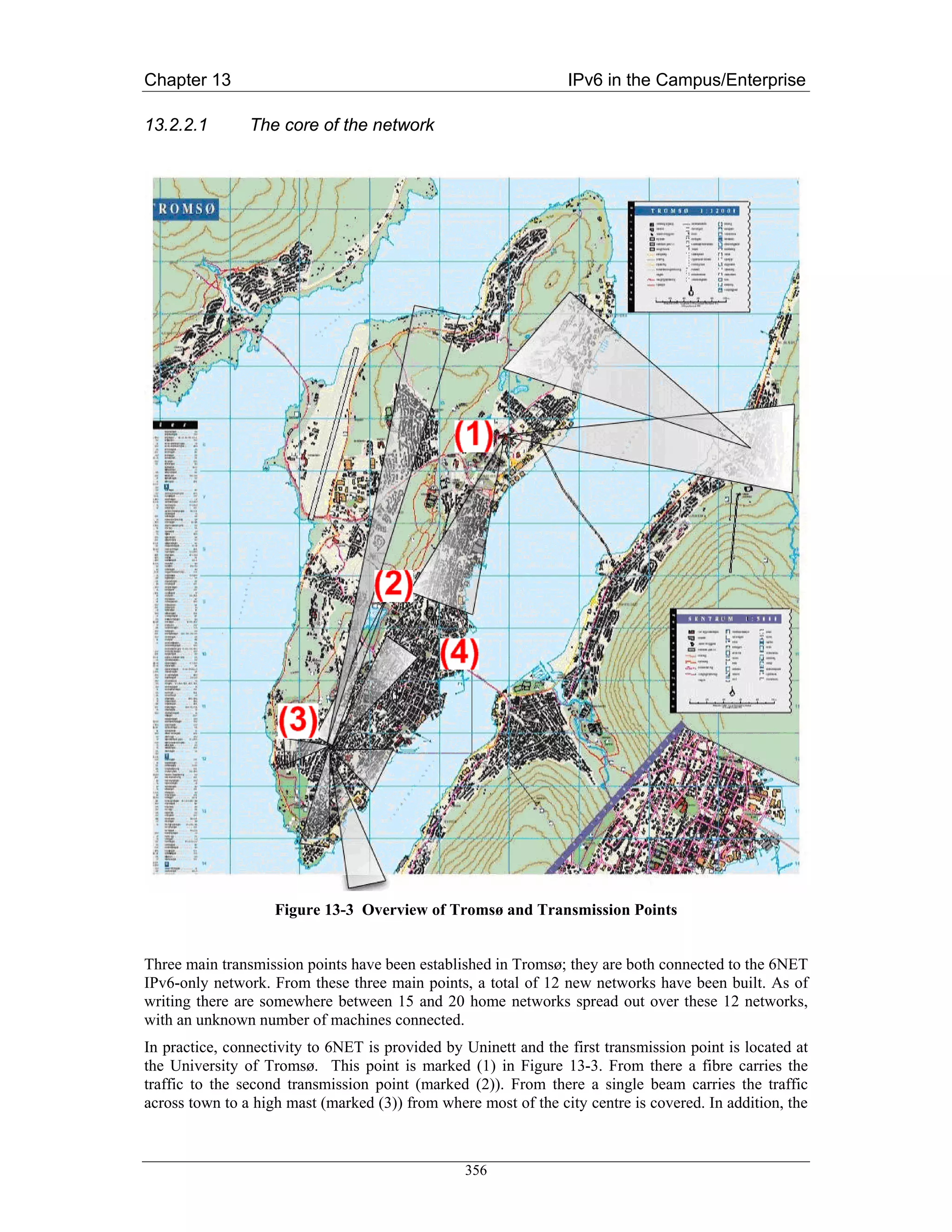
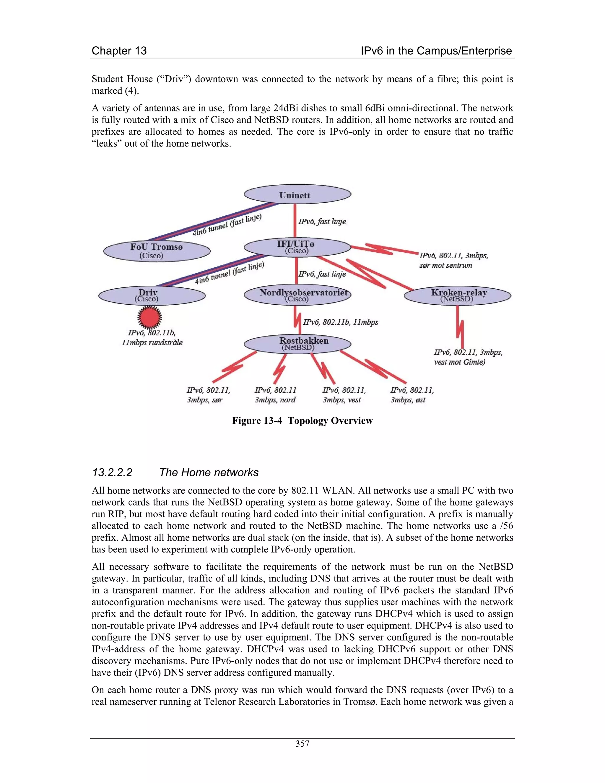
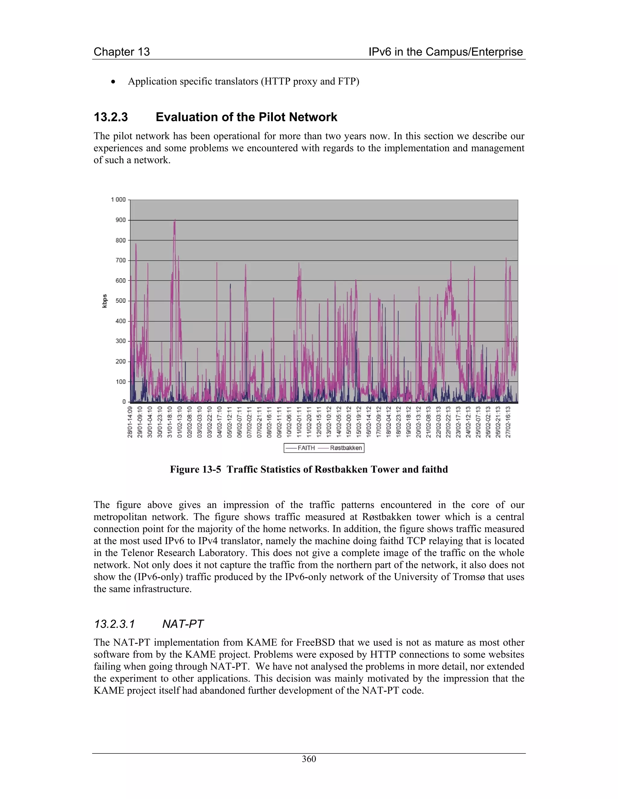

![Chapter 13 IPv6 in the Campus/Enterprise
13.3 Large Academic Department (University of Southampton)
In this section we begin by describing the systems components in this scenario of a large
“departmental” network (1,500+ users with around 1,000 hosts) that wishes to transition to support
IPv6. We describe the elements that need to be considered for the transition.
Southampton has been running IPv6 since 1996, but has only in the last two years adopted IPv6 as a
production service in its network.
This scenario assumes no IPv6 is deployed beforehand, although in reality the transition at
Southampton is already underway, in fact it is at the time of writing in a reasonably advanced stage.
Thus after a review of the systems components, we present an overview of the status to date, current
plans and next steps, and also the major remaining obstacles that have been identified.
Our motivation to deploy was in support of teaching, research projects, and communication with IPv6
networks (including those used by overseas students), while also encouraging innovation from staff
and students – indeed already we have seen new streamed radio (Surge/Virgin1) and multicast video
services (ECS-TV2) emerge.
This work has contributed to the IETF v6ops WG enterprise scenario descriptions and analysis. We
have documented our campus experience in an Internet Draft [Cho04a] and also documented the IEEE
802.1q VLAN approach to introducing IPv6 [Cho04b] that has also been used at Muenster (see
above). The [Cho04a] draft was built from a similar analysis as appears here.
13.3.1 Systems Components
The components fall into the following categories:
• Network components
• Address allocation components
• Services
• Host and device platforms
• User tools
We discuss these categories below.
In the light of the IETF v6ops WG activity on studying IPv6 network renumbering [RFC4192], we
also cite components where hardcoded IP(v4) addresses may be found, that may need consideration in
IPv6 networks. Further renumbering reporting can be found in D3.6.1 [D3.6.1] and D3.6.2 [D3.6.2].
13.3.1.1 Network
Physical connectivity (Layer 2)
The technologies used are:
• Switched Ethernet
• Gigabit Ethernet
• Wireless networking (802.11b)
1
http://www.ipv6.ecs.soton.ac.uk/virginradio
2
http://www.ecstv.ecs.soton.ac.uk
364](https://image.slidesharecdn.com/ipv6deployment-guide-110112200202-phpapp01/75/IPv6-Deployment-Guide-378-2048.jpg)
![Chapter 13 IPv6 in the Campus/Enterprise
Specific tools for remote host communications include:
• X11
• VNC
• PC Anywhere
13.3.2 Transition Status
Having described the components, we now outline the steps already taken towards transition at the
site. The focus here is to provide increasing IPv6 functionality in a dual-stack environment, with the
goal of allowing IPv6-only devices to be introduced and to operate successfully using only IPv6
transport (that does not mean they have to interoperate with all ‘legacy’ services, but they should be
able to use DNS, NTP, SMTP and similar basic services).
Because the Alcatel switch/router equipment does not route IPv6, an alternative method was required
to deliver IPv6 on the wire to existing IPv4 subnets. To enable this, IPv6 router advertisements were
delivered using a parallel IPv6 routing infrastructure. These IPv6-only routers support IEEE 802.1q
VLAN tagging; the BSD routers can inject a different IPv6 prefix onto each IPv4 subnet, using
congruent VLANs. The router tags the packets travelling towards the internal network with a
configured VLAN ID depending on the destination IPv6 prefix/link. This VLAN method is described
by the authors in [Cho04b], and illustrated in Figure 13-6.
Figure 13-6 Use of IPv6 VLANs at Southampton
As traffic in the site grows, multiple routers can be dedicated to this task for internal routing, or a
router with multiple interfaces. We currently have four routers with quad Fast Ethernet interfaces.
BSD allows multiple-VLAN tagging per interface, so in light traffic conditions the interface count can
370](https://image.slidesharecdn.com/ipv6deployment-guide-110112200202-phpapp01/75/IPv6-Deployment-Guide-384-2048.jpg)
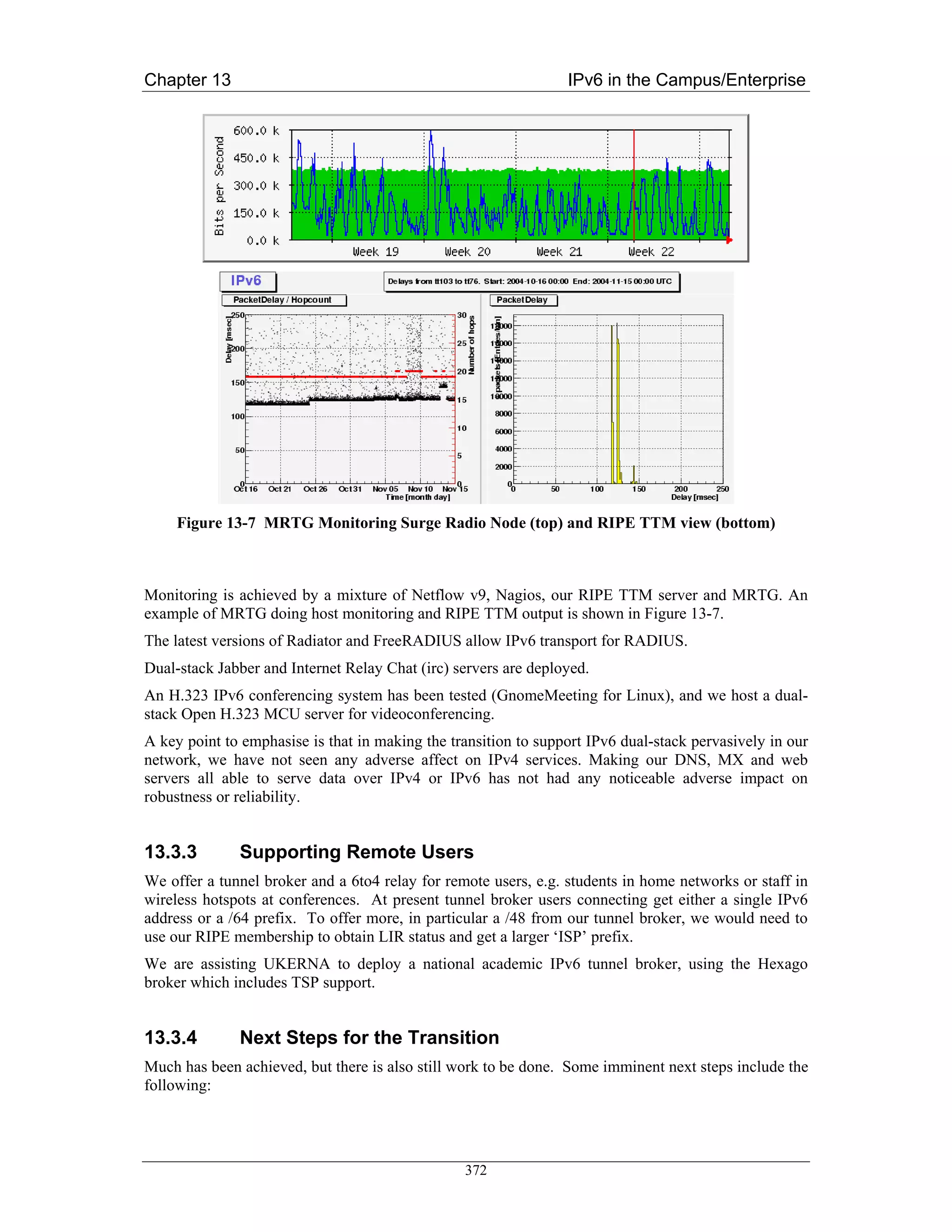
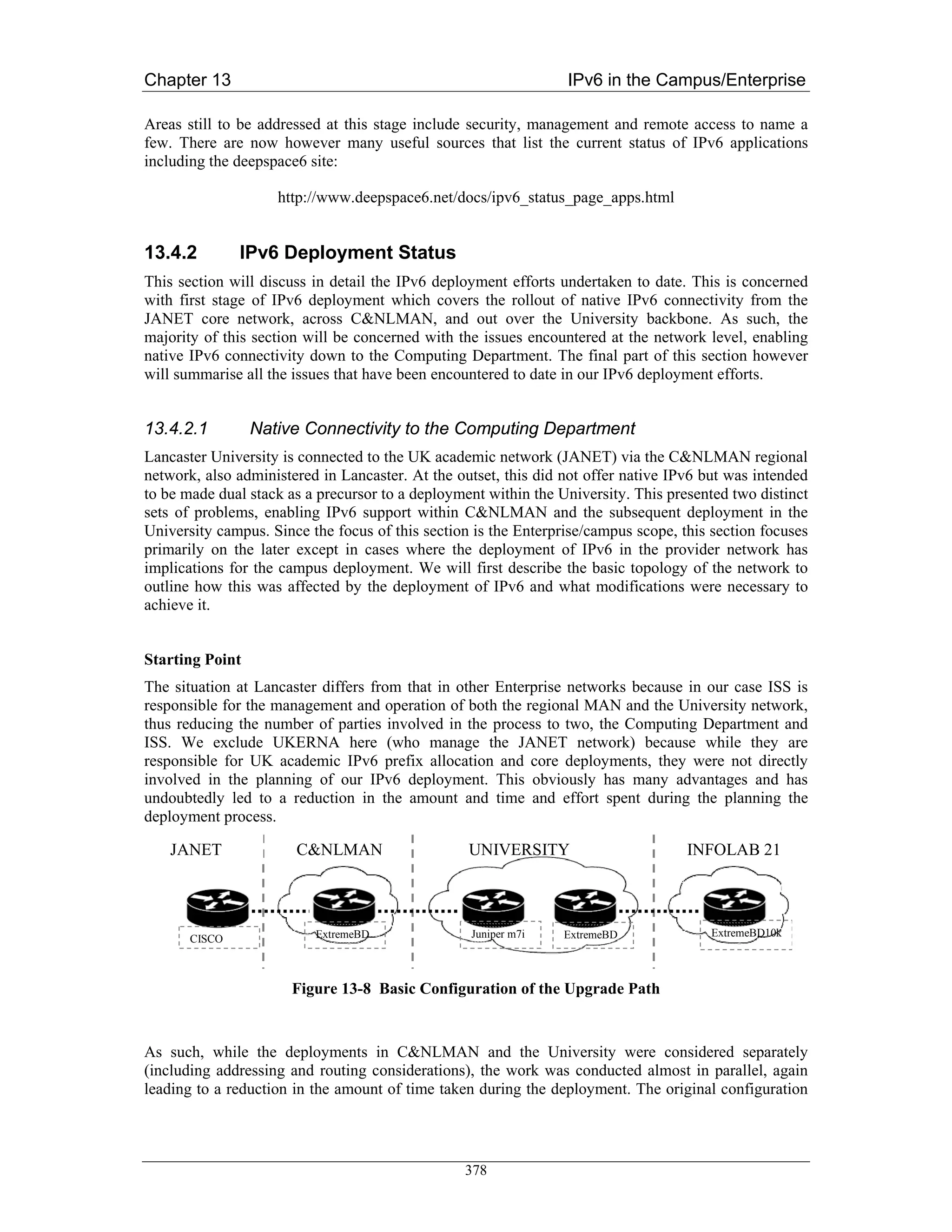
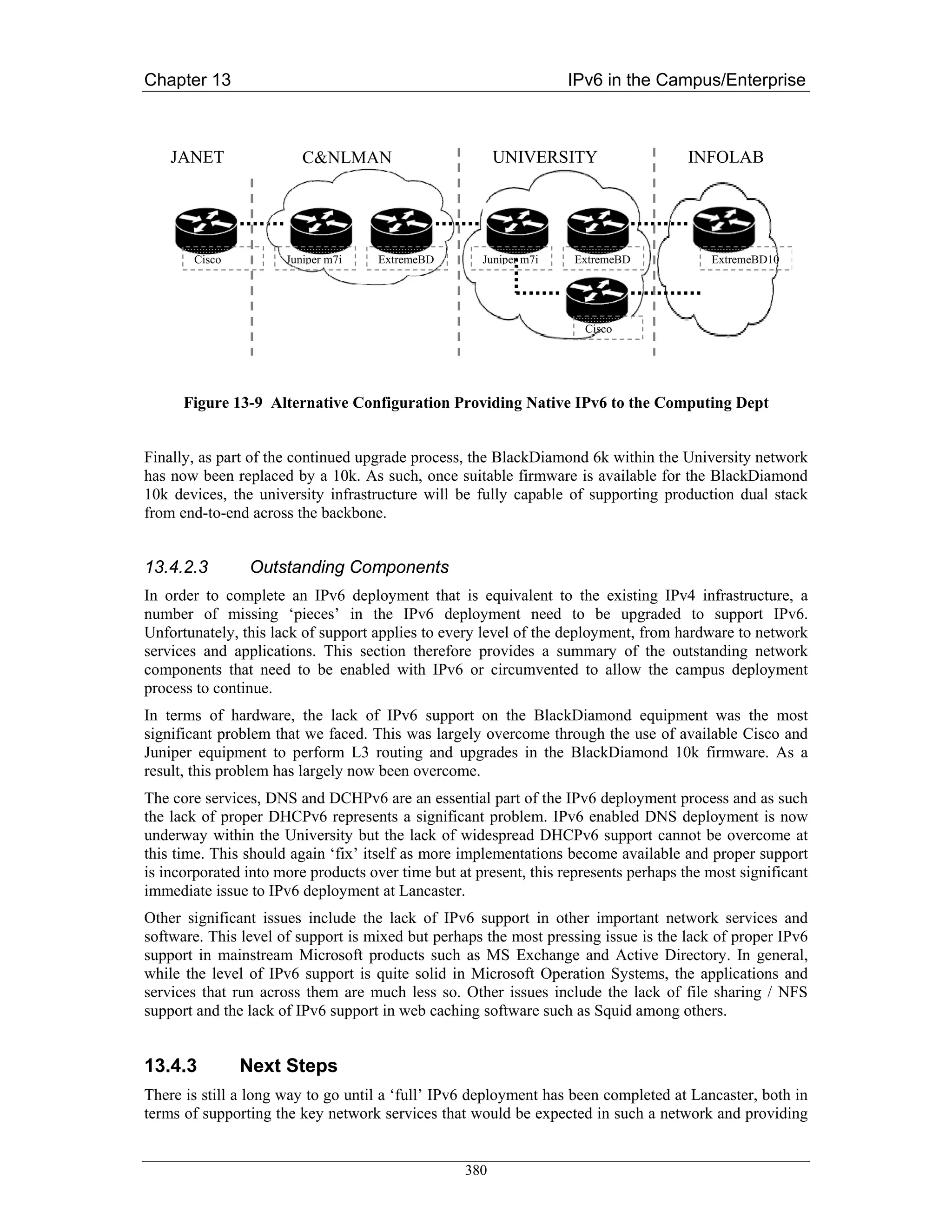
![Chapter 13 IPv6 in the Campus/Enterprise
13.5.2 School Deployment of IPv6 to Complement IPv4+NAT
This scenario has been covered in depth by the 6NET report on the IPv6 Deployment in the Greek
School Network [D5.14]. Here, IPv6 with global addressing is adding new possibilities to an
infrastructure previously focused on IPv4 + NAT.
13.5.3 IPv6 Access for Home Users
Here we consider home user networks (staff, students) wanting connectivity, possibly behind a NAT,
possibly with just a single machine, possibly with a dynamic IPv4 address.
The solutions available include
• Teredo
• Tunnel broker
• 6to4
Some tunnel broker implementations, especially with TSP, can support IPv4 NAT traversal and/or
dynamic IPv4 addresses. As described above, 6to4 can have reliability issues dependent on the relay
location (but is strong when used to connect just to other 6to4 sites, e.g. other home networks using it).
Teredo is a method of ‘last resort’, designed for use behind IPv4 NATs. The broker or 6to4 would
generally be preferred to Teredo.
13.6 Summary of Unexpected Results and Unforeseen Difficulties
The case studies above discuss the general scenarios and deployment procedures that were followed in
each case. In each case, the challenges in deployment were generally technical but understood, rather
than ‘exploratory’. Thus very few, if any, unexpected results or difficulties were encountered. Quite
the opposite – the deployments described have gone very well and have been very positive.
Here we repeat a small summary of the unforeseen issues captured in the scenarios above:
• A surprising level of fear, uncertainty and doubt (FUD) about the IPv6 technology by certain
administrators that we had to interact with.
• The fact that if you want to run a tunnel broker service to your staff or students, a /48 prefix is
not big enough for a campus unless the broker users only get a /64 prefix, which is not ideal.
• Lack of VLAN capability where it was desired, preventing the VLAN method being used
where desired in all cases.
• Variable performance in software driven VLAN tagging; Southampton’s BSD routers hit a
forwarding limit with the specific DLINK cards used.
• A desire by network administrators (managers) to use DHCPv6 even when IPv6 supports
stateless autoconfiguration. Sites seem used to managing their IP address assets.
• A desire to disable IPv6 Privacy Addresses to make management and monitoring simpler
(device identification simpler).
• Unexpected impact on IPv4 security when IPv6 is turned on. This happened in the Lancaster
case, but is resolved via a firmware upgrade
• The relative high performance of DSTM versus NAT-PT.
385](https://image.slidesharecdn.com/ipv6deployment-guide-110112200202-phpapp01/75/IPv6-Deployment-Guide-399-2048.jpg)
![Chapter 13 IPv6 in the Campus/Enterprise
• Various issues with totd at Tromso – interactions with certain DNS implementations, with use
of IP literals, and systems with AAAA records that do not offer all services over IPv6
transport.
• Some hardware problems to run IPv6 in old PCs, caused by lack of required multicast support
in old Ethernet cards. These can be replaced cheaply.
• Abuse of some transitioning relay services. The spammers will find you.
Although these have been overcome, they may represent generic issues that may resurface in similar
situations.
For a discussion of issues and challenges remaining for IPv6 deployment, see [D2.5.3].
13.7 Summary of tradeoffs made in solutions chosen
Many tradeoffs are related to the desirable properties of the mechanisms being chosen from, for
example:
• Which IPv4 and IPv6 functionality/connectivity is required?
• The cost of deploying dual-stack, versus IPv6-only with translation to communicate with IPv4
devices
• The cost to ‘the Internet architecture’ of a certain method, e.g. are relays expected to be
deployed by every ISP, or even every site? How do these relays interact?
• Security requirements – is the method open to relay abuse?
• Ease of management – how is the transition mechanism managed?
• Whether dynamic IPv4 addresses on the client need to be handled
• Whether IPv4 NAT traversal is needed from the client
• Whether just hosts or networks need to be connected
• How the solution scales – is there just one point of failure? Is load-sharing or balancing
supported?
• Resilience in the solution
• Who owns the transition components (ISP or end site)
• How the service is discovered or configured, if ‘plug and play’ is desirable
• Whether specific services are enabled, like multicast
• How optimal the routing is (or isn’t), e.g. whether there is any route optimisation method
• What performance penalty is suffered from encapsulation/translation methods
• Whether reverse DNS lookups are available for the method
• Accountability – how is usage reported and monitored, or identified?
There is no single, ‘best’ solution for all scenarios. Factors such as those listed above will determine
which is best for which scenario.
386](https://image.slidesharecdn.com/ipv6deployment-guide-110112200202-phpapp01/75/IPv6-Deployment-Guide-400-2048.jpg)
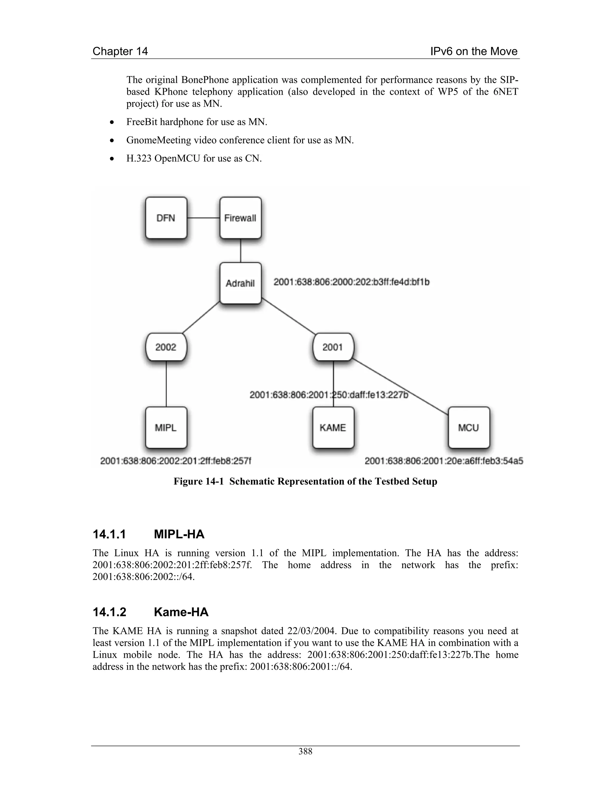
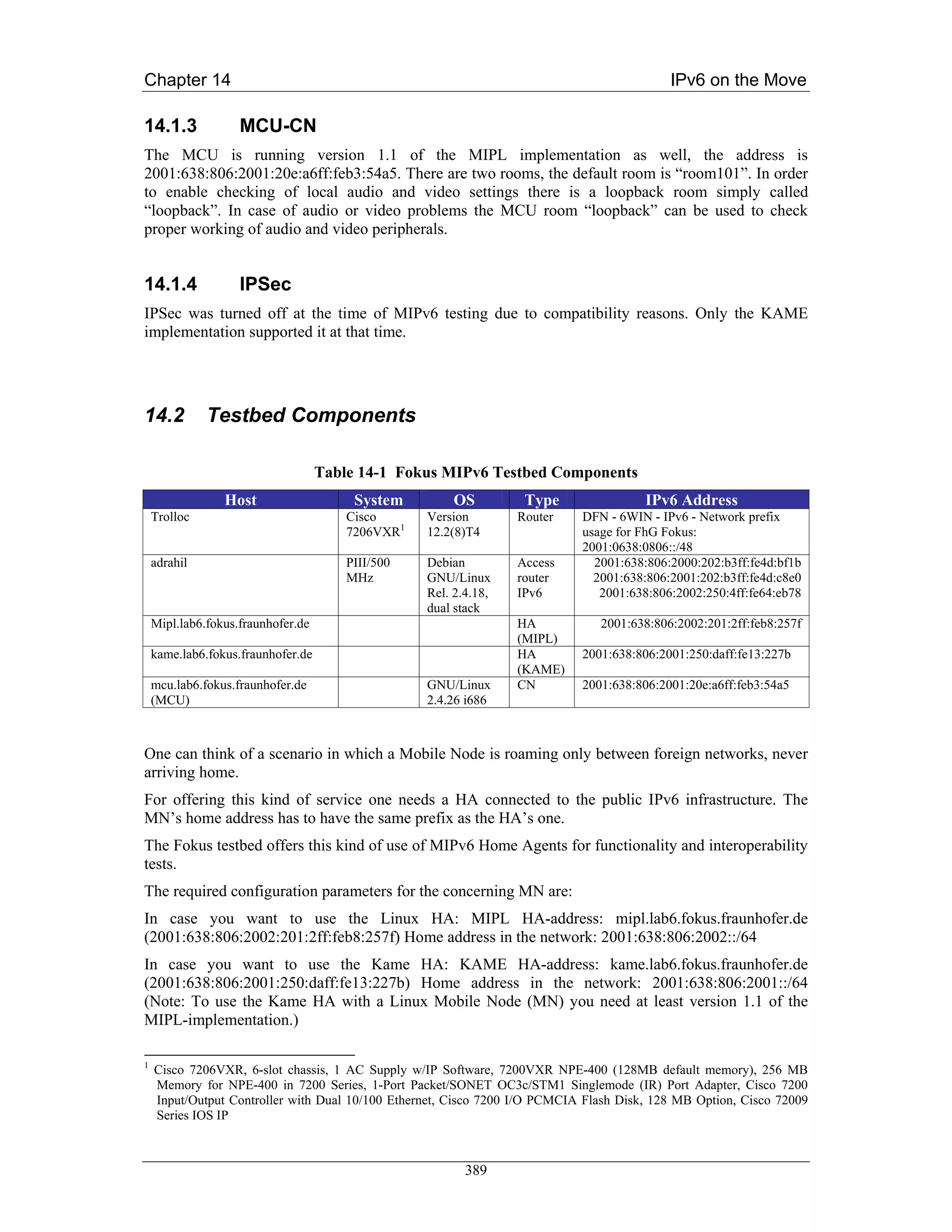

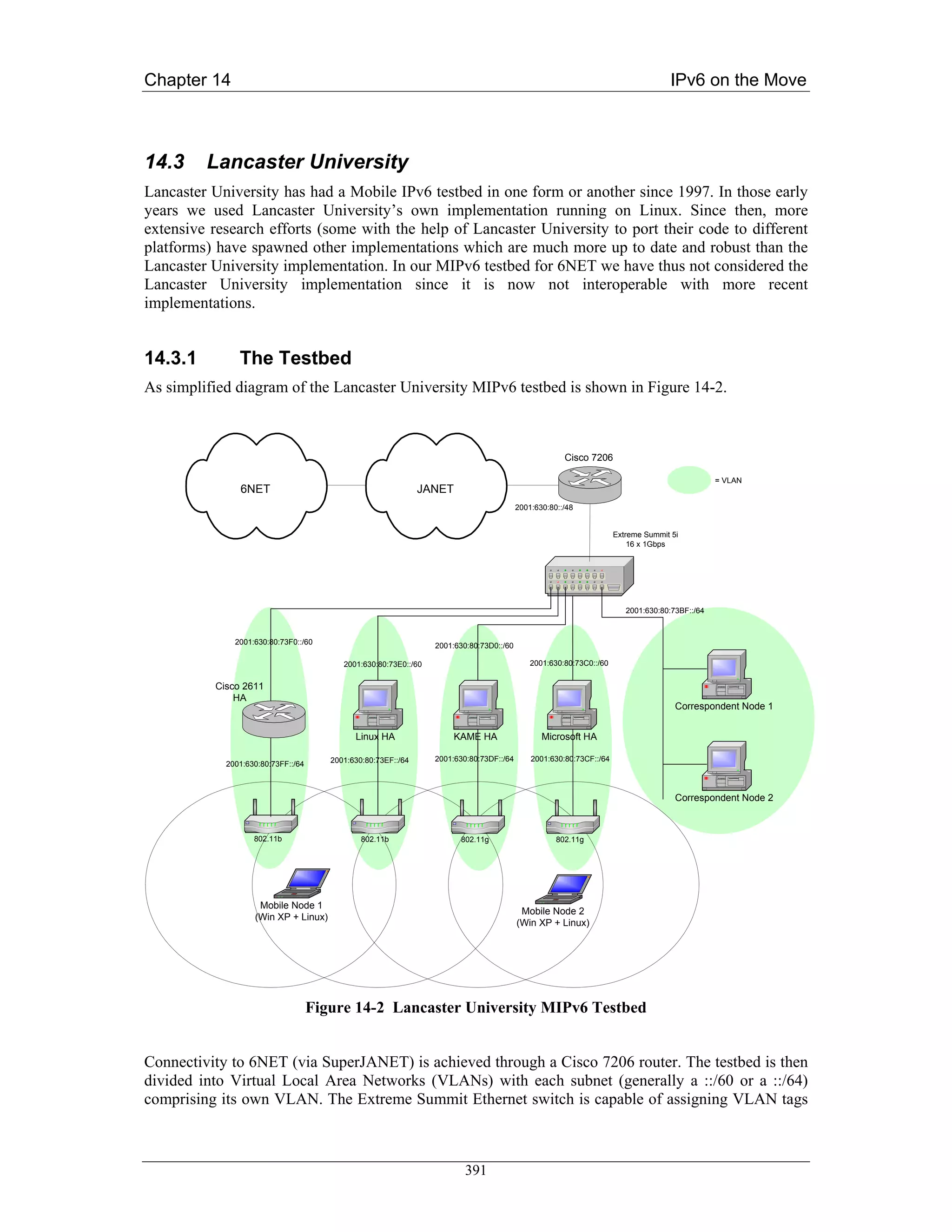
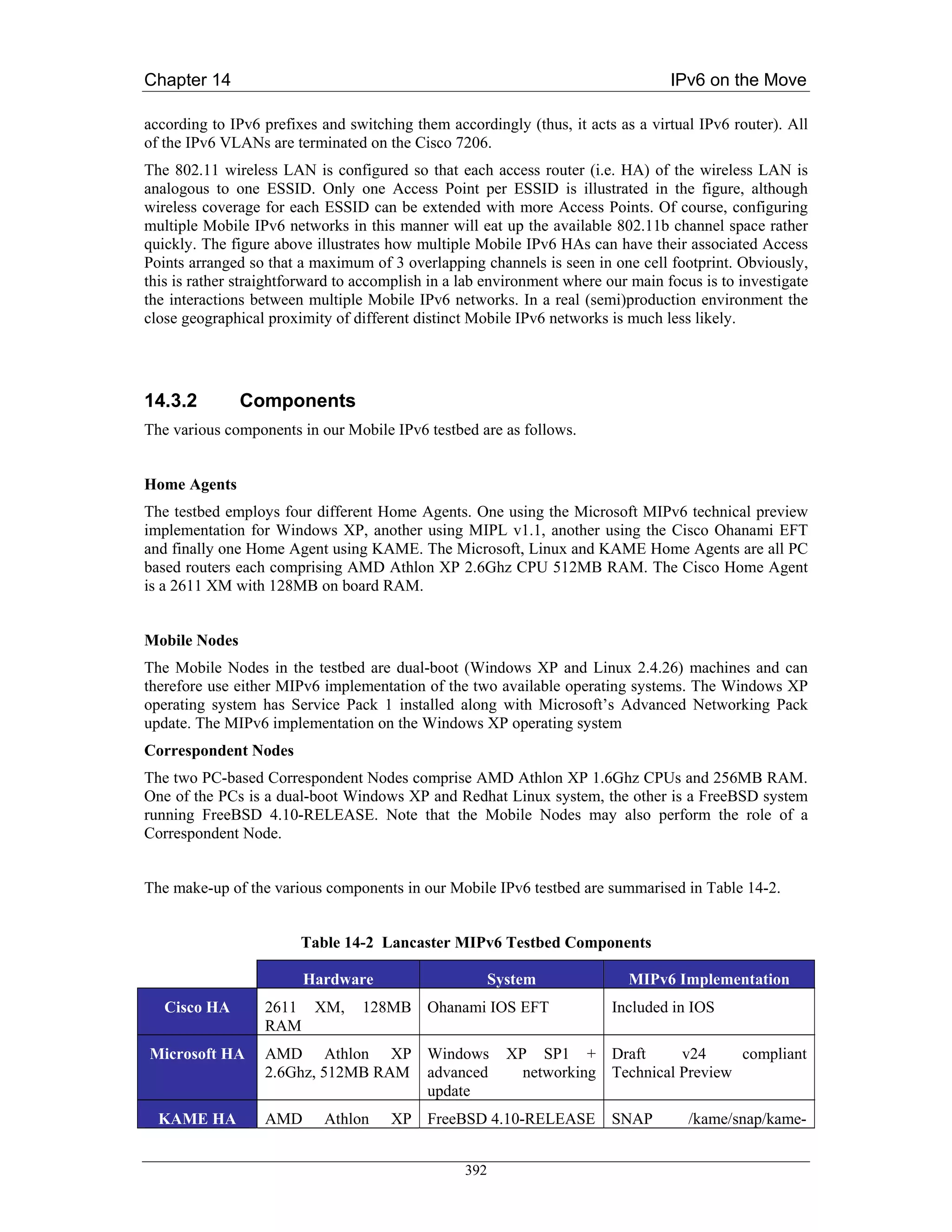
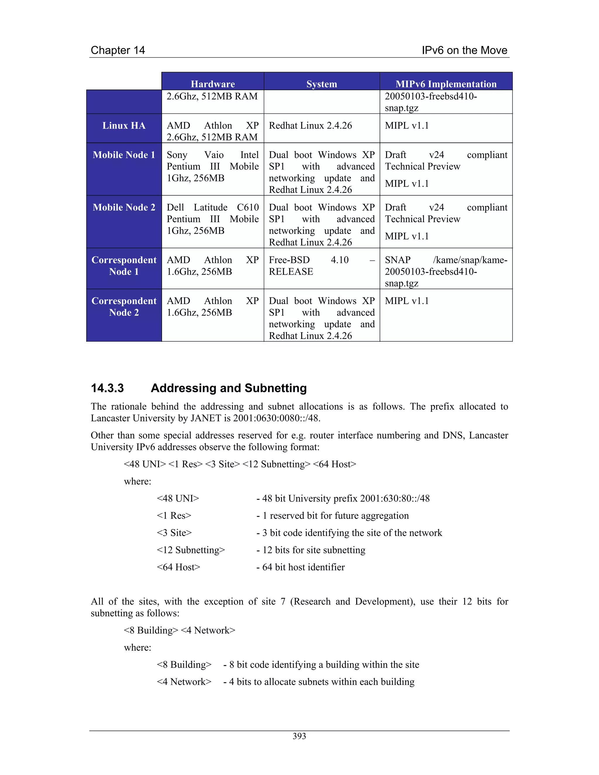
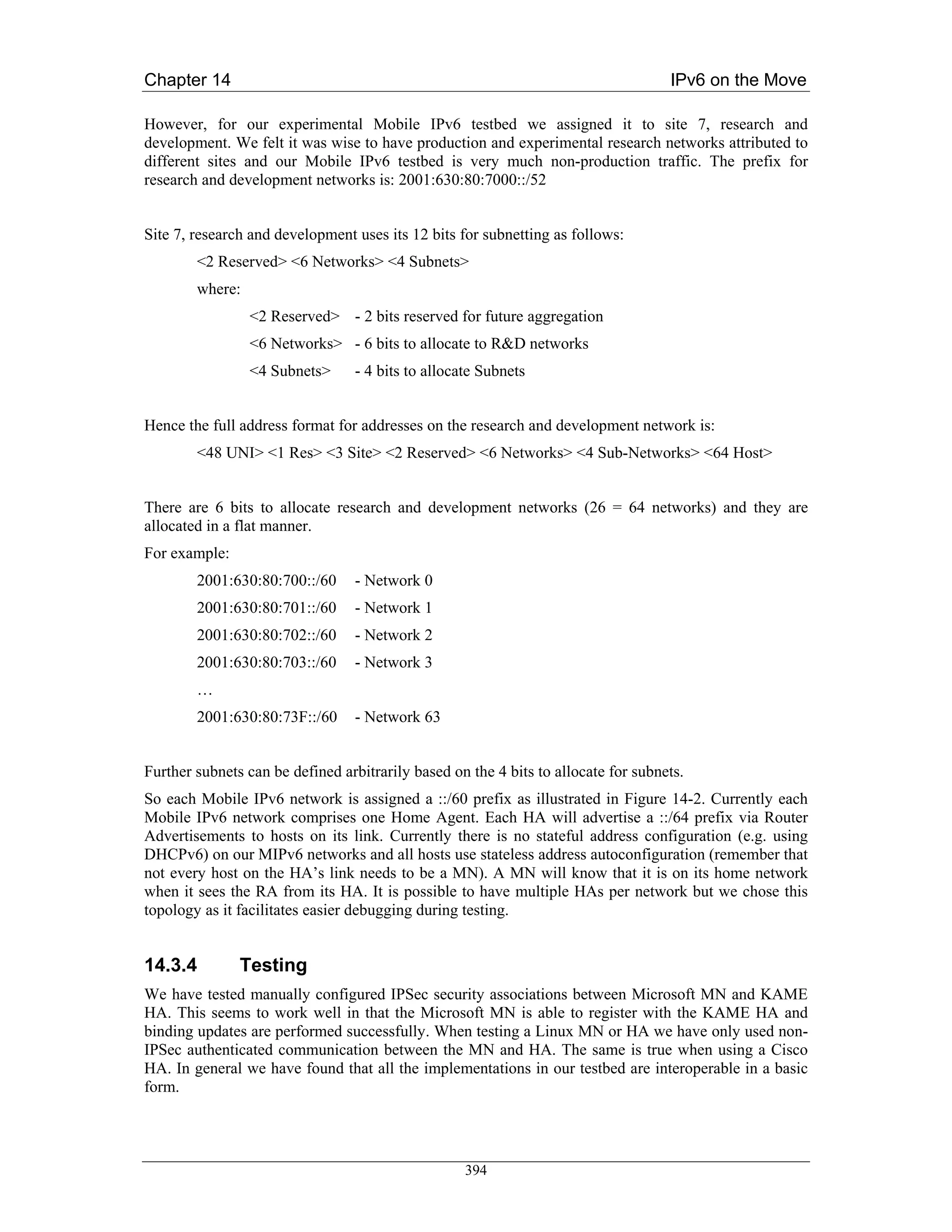
![Chapter 14 IPv6 on the Move
For obvious reasons we do not employ any AAA or access control mechanisms when performing
handover latency tests. This is especially important when using any streaming applications as the
delay incurred when waiting for network access to be granted can result in a considerable number of
lost packets. We have found that using IPerf [IPERF] between the CN and MN is a very useful tool for
discovering the extent of packet loss during handovers when comparing different network and
different tunings of the RA intervals.
Since each Home Agent also acts as the default router on its respective link as shown in Figure 14-2
we configure each Home Agent to announce unsolicited Router Advertisements at more frequent
intervals than the default. In general, we use a Router Advertisement interval of 1 second which is
sufficient for most adaptable TCP applications such as email, web, ftp etc. However, we have noticed
considerable (i.e. unpleasant) disruption when using a 1 second interval when streaming video and/or
audio. Reducing the interval to around 300ms seems to be fair benchmark to set for supporting
streaming media. Although it is possible to reduce the interval even further, in most tests we did not
observe enough improvement in the stream disruption to justify the extra link bandwidth and Home
Agent CPU cycles being used.
Initially, the most simple way of testing the operation of the MIPv6 testbed is by testing basic
connectivity between the Mobile Node and Correspondent Node with a stream of ping requests from
the Correspondent Node to the Mobile Mode while the Mobile Node moves between its home network
and a foreign network. In a correctly configured Mobile IPv6 testbed, the ping requests should
continue to be answered as the Mobile Node moves. Sometimes we observe one ping timing out as the
packet is lost. This can occur if the ping request is sent just as the Mobile Node becomes unreachable
in its original location but has not yet completed the binding update procedure to be reachable at its
new location. However, on a properly configured testbed we rarely observe more than one ping
timeout.
For testing that TCP connections survive movement of the Mobile Node, a simple test is to run telent
or similar (using the client and server in either combination of Mobile Node and Correspondent Node)
and observe that the session remains active after movement. You should not observe any noticeable
effects (save some possible interruption in character echo on the terminal) if all is configured
correctly.
Beyond these basic tests some users may want to experiment with the TAHI compliance test suite
described at [TAHI].
14.3.4.1 Handover Latency Tests
Figure 14-3 shows the small MIPv6 testbed used for performing the handover tests. A MN running
MIPL v1.1 is away from home (the HA also running MIPL v1.1) and can attach to one of two
networks represented by the SSIDs ‘roam1’ and ‘roam2’. We decided to conduct handover tests from
one foreign network to another (e.g. rather than from home network to foreign network) as the nature
of mobility implies that when one is mobile, one is very rarely located at the home network.
Handovers from one network to another were forced by turning off one of the APs so that the MN
would immediately associate with the other AP and thus receive different RAs than on the previously
connected network.
The handover times were measured from the point at which the AP is switched off (link down
notification) to when the Binding Acknowledgement is received from the Correspondent Node with
each event being timestamped in the relative logs. Note that the Return Routability protocol was
enabled for Route Optimisation.
395](https://image.slidesharecdn.com/ipv6deployment-guide-110112200202-phpapp01/75/IPv6-Deployment-Guide-409-2048.jpg)
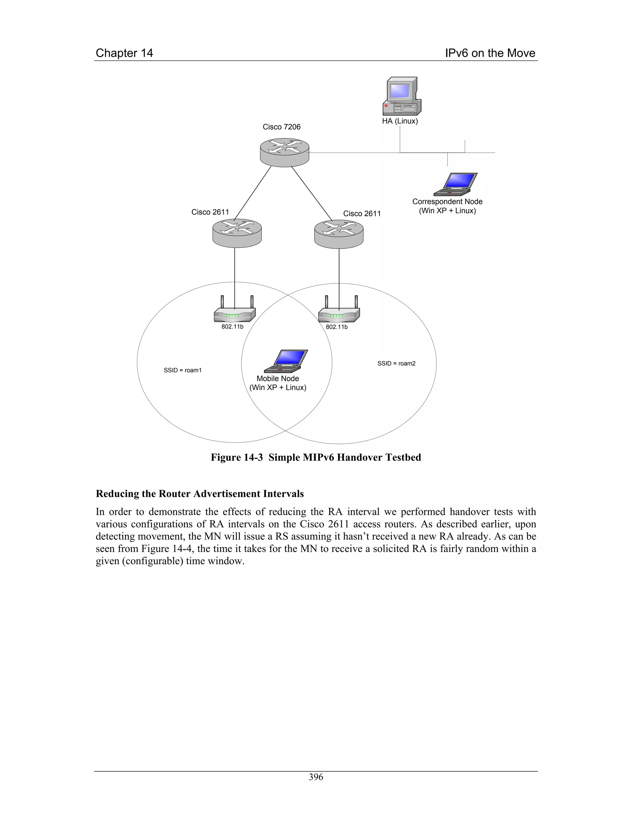
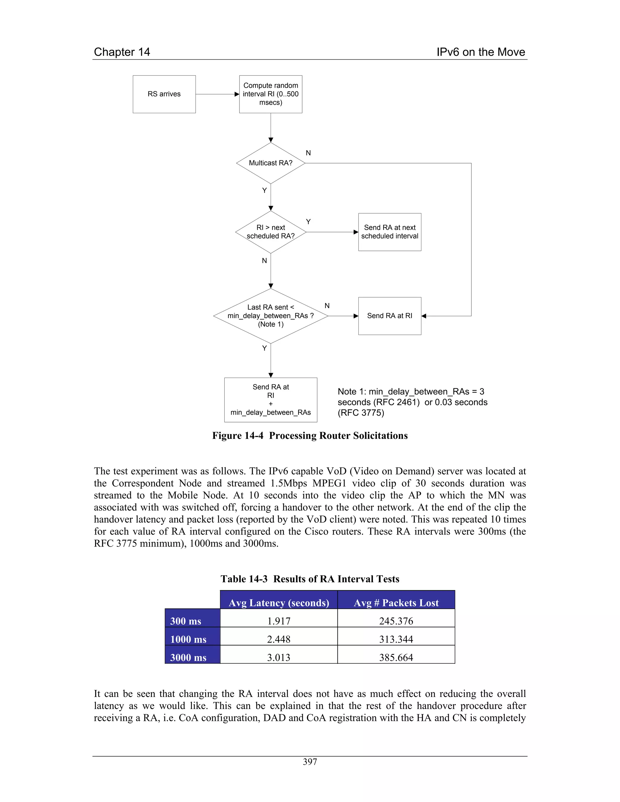
![Chapter 14 IPv6 on the Move
unaffected by reducing the RA interval. One can also see the number of packets lost in the video
stream. On the client playback the stream would recover itself after handover but the break in the
video and audio seemed about 1 or 2 seconds longer than the handover latency reported in the logs. It
is easy to conclude that even tuning the RA interval to the lowest possible value will not suffice for
real-time voice and video applications in a mobile environment.
Unicasting Solicited RAs
Another possible trick is to change the default behaviour of neighbour discovery so that a Router
Solicitation is answered with a unicast RAs rather than the default multicast RA. In the standard
algorithm depicted in Figure 14-4 it can be seen how a unicast RA only incurs the random delay
interval and is not affected by the configured RA interval parameter (since this only applies to
multicast RAs). To see what effect this would have on handover latency we had to replace a 2611
router with a linux PC based equivalent (since we were unable to configure the IOS accordingly).
Table 14-4 Using Unicast RAs
Avg Latency (seconds) Avg # Packets Lost
Unicast RA 2.072 265.216
From the table we can see that the results are slightly worse than the best we can get from configuring
the RA interval. However, since the random interval is between 0 and 500 ms (the
MAX_RA_DELAY_TIME constant in [RFC2461], we are unable to reduce this parameter further.
Eliminating DAD / Optimistic DAD
By removing the DAD procedure altogether we can reduce the handover latency even further
(potentially by a second or so). However, removing this check altogether is not a realistic option both
in terms of ratification by the IETF or by tuning an implementation’s configuration. Thus, we are left
with the option of fine tuning the DAD procedure in some way that reduces the time it takes for a MN
to be able to use its CoA. A procedure called ‘Optimistic DAD’ which modifies [RFC2461] and
[RFC2462] is proposed in [Moo05], which essentially allows a CoA to be used before it has
completed DAD. The CoA is marked as ‘optimistic’ as opposed to ‘tentative’ before completing DAD
and is marked as ‘preferred’ once DAD is complete.
Unfortunately, we have not been able to source a suitable implementation of Optimistic DAD with
which to test. An implementation will soon be made available from Monash University, but this will
appear too late for the lifetime of the 6NET project.
Conclusions
Our tests have demonstrated that even with fine tuning the parameters of routers for optimum MIPv6
handover performance, we still do not approach anywhere near good enough handover times for real-
time voice/video applications.
We must therefore conclude that MIPv6, in its current form is not by itself sufficient to be the de-facto
mobility management model in the mobile IPv6 Internet. Further optimisations relating to handover
performance must be made in order to support interactive and real-time IPv6 applications in a mobile
context.
398](https://image.slidesharecdn.com/ipv6deployment-guide-110112200202-phpapp01/75/IPv6-Deployment-Guide-412-2048.jpg)
![Chapter 14 IPv6 on the Move
We have examined the fast handover protocol for MIPv6, FMIPv6 [RFC4068]. This aims to improve
handover latency by eliminating IPv6 configuration latency and also prevents packet loss by the use of
a bi-directional tunnel while physical movement and MIPv6 CoA registration are taking place.
To the best of our knowledge no implementation has yet been developed for us to perform handover
tests. Yet this does not prevent us from reasoning that FMIPv6 will indeed reduce handover latency in
almost all cases. In some cases, e.g. predicted handovers and relatively infrequent movement FMIPv6
promises to be sufficient for the real-time applications, most notably the killer mobile application
VoIP. However, without being able to perform real tests it would be rather hasty to take this for
granted.
399](https://image.slidesharecdn.com/ipv6deployment-guide-110112200202-phpapp01/75/IPv6-Deployment-Guide-413-2048.jpg)
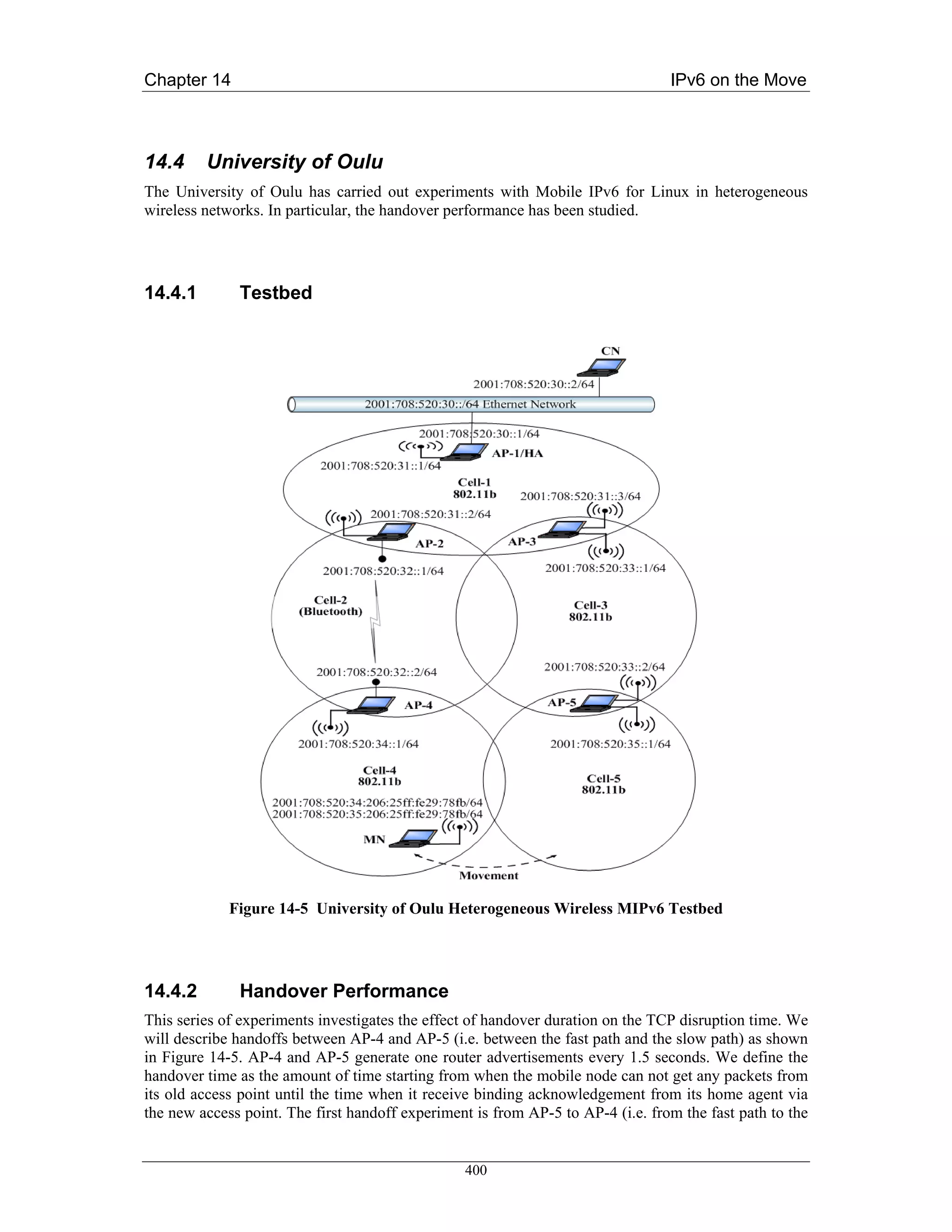
![Chapter 14 IPv6 on the Move
slow path). The MN starts sending TCP traffic to the CN using AP-5 and moves towards AP-4. Figure
14-6 shows the time sequence number plot of the TCP connection including the handover time. We
found that it takes around 4.9 seconds to handoff from AP-5 to AP-4. The TCP disruption time was
found to be 10.5 seconds. As illustrated in the figure, the TCP goes through 4 consecutive timeouts
and retransmissions. Because of TCP exponential backoff mechanism, TCP doubles the size of its
timeout interval each consecutive timeouts. Following the handover, the TCP waits for the last timeout
to elapse before starts sending data using the new care-of-address. This result demonstrate that the
handover duration contribute approximately 40% of the TCP disruption time. The remaining time
delay is due to TCP congestion control mechanism. The average handover duration and TCP
disruption time are shown in Table 14-5.
Table 14-5 Handover Duration and TCP Disruption Time
Average handover Average TCP disruption time
duration [seconds] [seconds]
From fast to slow path 3.94 8.40
From slow to fast path 1.49 3.91
Figure 14-6 TCP Packet Trace During Handover from AP-5 to AP-4
401](https://image.slidesharecdn.com/ipv6deployment-guide-110112200202-phpapp01/75/IPv6-Deployment-Guide-415-2048.jpg)
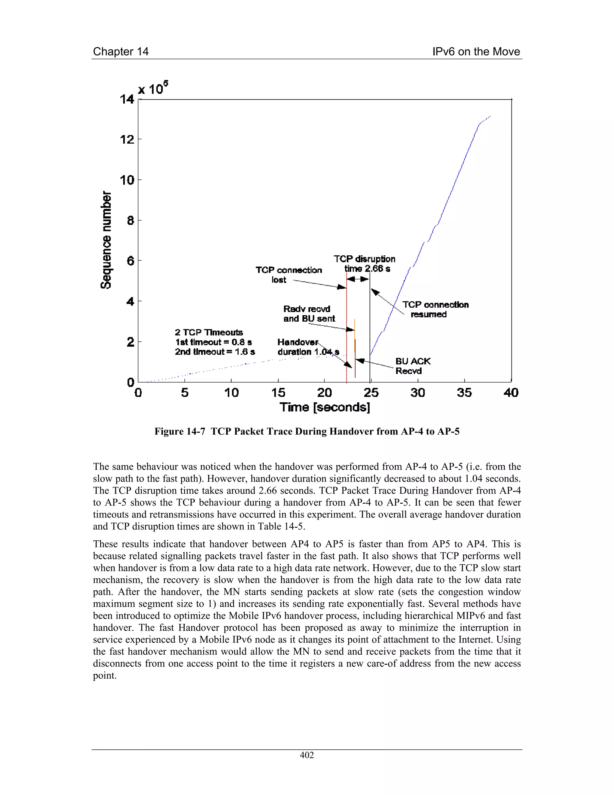
![Bibliography
Bibliography
[8021x] LAN MAN Standards Committee of the IEEE Computer Society, “Port Based Network
Access Control”, IEEE Standard 802.1x, June 2001.
[AD05] C. Aoun, E. Davies, “Reasons to Move NAT-PT to Experimental”, IETF Internet Draft
draft-ietf-v6ops-natpt-to-exprmntl-01.txt (work in progress), January 2005.
[BCKR05] T. Bates, R. Chandra, D. Katz, Y, Rekhter, “Multiprotocol Extensions for BGP-4”, IETF
Internet Draft draft-ietf-idr-rfc2858bis-07.txt, August 2005.
[Bel57] R. Bellman, “Dynamic Programming”, Princeton University Press, 1957.
[BG92] D. Bertsekas, R. Gallagher, “Data Networks”, Second edition, Prentice Hall, 1992, ISBN
0-13-200916-1.
[BP02] M. Blanchet, O. Medina, F. Parent, “DSTM Tunnel Setup using TSP”, IETF Internet Draft
draft-blanchet-ngtrans-tsp-dstm-profile-01.txt, July 2002.
[BP05] M. Blanchet , F. Parent, “IPv6 Tunnel Broker with the Tunnel Setup Protocol (TSP)”,
IETF Internet Draft draft-blanchet-v6ops-tunnelbroker-tsp-03.txt (work in progress),
August 2005.
[Bou05] J. Bound, “Dual Stack IPv6 Dominant Transition Mechanism (DSTM)”, IETF Internet
Draft draft-bound-dstm-exp-03.txt (work in progress), June 2005.
[Cho04a] T. Chown, “IPv6 Campus Transition Scenario Description and Analysis”, IETF Internet
Draft draft-chown-v6ops-campus-transition-01.txt, October 2004.
[Cho04b] T. Chown, “Use of VLANs for IPv4-IPv6 Coexistence in Enterprise Networks”, IETF
Internet Draft, draft-chown-v6ops-vlan-usage-02.txt, October 2004.
[Cla05] B. Claise, “IPFIX Protocol Specification”, IETF Internet Draft draft-ietf-ipfix-protocol-
19.txt, September 2005.
[D1.1] 6NET Deliverable 1.1, “Design and Implementation of the Testbed Infrastructure”, April
2002.
[D1.2] 6NET Deliverable 1.2, “Operational Procedures to be Followed by 6NET NOC”, April
2002.
[D2.2.4] 6NET Deliverable 2.2.4, “Final IPv4 to IPv6 Transition Cookbook for Organisational/
ISP (NREN) and Backbone Networks.”, February 2005.
[D2.3.4] 6NET Deliverable 2.3.4, “Final IPv4 to IPv6 transition cookbook for end site networks/
universities”, June 2005.
[D2.4.2] 6NET Deliverable 2.4.2, “Final report on IPv6-specific implications for Wireless
LAN/MAN transition to IPv6”, September 2003.
[D2.5.3] 6NET Deliverable 2.5.3, “Issues for IPv6 deployment (missing pieces for IPv6
deployment and IPv6-only operation)”, June 2005.
[D3.1.1] 6NET Deliverable 3.1.1, “IPv6 Routing Plan for the 6NET Network”, March 2002.
[D3.1.2] 6NET Deliverable 3.1.2, “IPv6 cookbook for routing, DNS, intra-domain multicast, inter-
domain multicast, security”, November 2004.
[D3.2.1] 6NET Deliverable 3.2.1, “IPv6 DNS service for the 6NET network”, March 2002.
403](https://image.slidesharecdn.com/ipv6deployment-guide-110112200202-phpapp01/75/IPv6-Deployment-Guide-417-2048.jpg)
![Bibliography
[D3.2.3] 6NET Deliverable 3.2.3, “DHCPv6 implementation and test report”, January 2003.
[D3.4.1] 6NET Deliverable 3.4.1, “IPv6 Intra-domain multicast service”, December 2002.
[D3.4.2] 6NET Deliverable 3.4.2, “Inter-domain Multicast”, December 2004.
[D3.5.1] 6NET Deliverable 3.5.1, “Secure IPv6 Operation: Lessons learned from 6NET”, January
2005.
[D3.6.1] 6NET Deliverable 3.6.1, “Cookbook for IPv6 Renumbering of SOHO and Backbone
Networks”, June 2005.
[D3.6.2] 6NET Deliverable 3.6.2, “Cookbook for IPv6 Renumbering of ISP and Enterprise
Networks”, June 2005.
[D4.1.3] 6NET Deliverable 4.1.3, “Mobile IPv6 Handovers: Performance Analysis and
Evaluation”, June 2005.
[D4.1.4] 6NET Deliverable 4.1.4, “Final Mobile IPv6 Support Guide”, February 2005.
[D4.1.5] 6NET Deliverable 4.1.5, “Multicast with mobile hosts: analysis and performance
evaluation”, January 2005.
[D4.2.1] 6NET Deliverable 4.2.1, “IPv6 Wireless LAN Access Issues”, July 2002.
[D4.2.2] 6NET Deliverable 4.2.2, “Framework for the Support of IPv6 Wireless LANs, Version 2”,
October 2004.
[D4.3.3] 6NET Deliverable 4.3.3, “Evaluation report on the advantages demonstrated from use of
IPv6 dynamic VPNs over different technologies”, March 2005.
[D4.4.2] 6NET Deliverable 4.4.2, “Final Report on IPv6 QoS tests”, April 2005.
[D4.5.3] 6NET Deliverable 4.5.3, “Evaluation of Multihoming Solutions”, February 2005.
[D5.1] 6NET Deliverable 5.1, “Specification of IPv6 applications to be developed within the
project”, May 2002.
[D5.5] 6NET Deliverable 5.5, “Definition of generic framework for IPv6 applications trials and
evaluation”, March 2003.
[D5.14] 6NET Deliverable 5.14: “IPv6 Deployment in the Greek School Network”, June 2005.
[D5.15] 6NET Deliverable 5.15, “Final report on applications development and evaluations
(including descriptions of the demonstrators of WP5), and PoP deployment”, June 2005.
[D6.1.2] 6NET Deliverable 6.1.2, “Management Architecture Specifications”, January 2003.
[D6.2.2] 6NET Deliverable 6.2.2, “Operational procedures for secured management with
transition mechanisms”; February 2003.
[D6.2.4] 6NET Deliverable 6.2.4, “Final report on IPv6 management tools, developments and
tests”, September 2004.
[D6.3.3] 6NET Deliverable 6.3.3, “Final report on IPv6 management and monitoring architecture
design, tools, and operational procedures. Recommendations.”, October 2004.
[DHJNZ04] S. Deering, B. Haberman, T. Jinmei, E. Nordmark, B. Zill, “IPv6 Scoped Address
Architecture”, IETF Internet Draft draft-ietf-ipv6-scoping-arch-02.txt (work in progress),
August 2004.
[DKS05] E. Davies, S. Krishnan, P. Savola, “IPv6 Transition/Co-existence Security
Considerations”, IETF Internet Draft draft-ietf-v6ops-security-overview-02.txt (work in
progress), July 2005.
[Dro02] R. Droms, “A Guide to Implementing Stateless DHCPv6 Service”, IETF Internet Draft
draft-droms-dhcpv6-stateless-guide-01.txt, October 2002.
404](https://image.slidesharecdn.com/ipv6deployment-guide-110112200202-phpapp01/75/IPv6-Deployment-Guide-418-2048.jpg)
![Bibliography
[DS04] F. Dupont, P. Savola, “RFC 3041 Considered Harmful”, IETF Internet Draft draft-
dupont-ipv6-rfc3041harmful-05.txt, June 2004.
[Dur03] A. Durand, “Issues with NAT-PT DNS ALG in RFC2766”, IETF Internet Draft draft-
duran-v6ops-natpt-dns-alg-issues-00.txt, September 2003.
[ENST] ENST DSTM web site: http://www.ipv6.rennes.enst-bretagne.fr/dstm/.
[FC05] D. Farinacci, Y. Cai, “Anycast-RP using PIM”, IETF Internet Draft draft-ietf-pim-
anycast-rp-04.txt (work in progress), August 2005.
[FHHK05] B. Fenner, M, Handley, H. Holbrook, I. Kouvelas, “Protocol Independent Multicast -
Sparse Mode (PIM-SM): Protocol Specification (Revised)”, IETF Internet draft draft-ietf-
pim-sm-v2-new-11.txt, October 2004.
[FJ94] S. Floyd, V. Jacobson, “The synchronization of periodic routing messages”, IEEE/ACM
Transactions on Networking, vol. 2, no. 2, pp. 122-136, 1994.
[FF62] L. R. Ford, D. R. Fulkerson, “Flows in Networks”, Princeton University Press, 1962.
[HH05] R. Hinden, B. Haberman, “Unique Local IPv6 Unicast Addresses”, IETF Internet Draft
draft-ietf-ipv6-unique-local-addr-09.txt, January 2005.
[Hop03] C. E. Hopps, “Routing IPv6 with IS-IS”, IETF Internet Draft draft-ietf-isis-ipv6-05.txt
(work in progress), January 2003.
[Hui05] C. Huitema, “Teredo: Tunneling IPv6 over UDP through NATs”, IETF Internet Draft
draft-huitema-v6ops-teredo-05.txt (work in progress), April 2005.
[IPERF] IPerf Homepage, http://dast.nlanr.net/Projects/Iperf/ .
[Kal03] V. Kalusivalingam, “Timezone Specifier Option for DHCPv6”, IETF Internet Draft draft-
ietf-dhc-dhcpv6-opt-tz-00.txt, November 2003.
[Mar01] M. G. Marsh, “Policy Routing Using Linux”, Sams Publishing 1998, ISBN 0-672-32052-
5.
[MFR78] J. M. McQuillan, G. Falk, I. Richer, “A review of the development and performance of the
ARPANET routing algorithm”, IEEE Transactions on Communications, vol. 26, no. 12,
pp. 1802-1811, December 1978.
[MHL05] M. Mathis, J. Heffner, K. Lahey, “Path MTU Discovery”, IETF Internet Draft draft-ietf-
pmtud-method-04.txt, February 2005.
[Moh01] J. Mohacsi, “IPv6 firewalls”, presentation at the 5th TF-NGN meeting, October 2001
available at http:///skye.ki.iif.hu/~mohacsi/athens_tf_ngn_ipv6_firewalls.pdf.
[Moh04] J.Mohacsi, “Security of IPv6 from firewalls point of view”, presentation at TNC2004
conference, June 2004, available at http://www.terena.nl/conferences/tnc2004/
programme/presentations/show.php?pres_id=115.
[Moo05] N. Moore, “Optimistic Duplicate Address Detection”, IETF Internet Draft draft-ietf-ipv6-
optimistic-dad-06.txt, September 2005.
[NDK05] T. Narten, R. Draves, S. Krishnan, “Privacy Extensions for Stateless Address
Autoconfiguration in IPv6”, IETF Internet-Draft draft-ietf-ipv6-privacy-addrs-v2-04.txt,
May 24, 2005.
[NG05] E. Nordmark, R. Gilligan, “Basic Transition Mechanisms for IPv6 Hosts and Routers”,
Internet Draft, draft-ietf-v6ops-mech-v2-07.txt (work in progress), March 2005.
[PSS05] T. Przygienda, N. Shen, N. Sheth, “M-ISIS: Multi Topology (MT) Routing in IS-IS”, IETF
Internet Draft draft-ietf-isis-wg-multi-topology-10.txt (work in progress), May 2005.
405](https://image.slidesharecdn.com/ipv6deployment-guide-110112200202-phpapp01/75/IPv6-Deployment-Guide-419-2048.jpg)
![Bibliography
[Pyth-Lib] Guido van Rossum, Fred L. Drake, “Python Library Reference”, Release 2.4.1
(http://docs.python.org/lib/lib.html), March 2005.
[RB05] A. Reddy, J. Bound, “Stack Transition Mechanism (DSTM) Options for DHCPv6”, IETF
Internet Draft draft-reddy-dhcpv6-opt-dstm-exp-00.txt (work in progress), April 2005.
[RFC1058] C. Hedrick, “Routing Information Protocol”, IETF Request for Comments 1058, June
1988.
[RFC1191] J. Mogul, S. Deering, “Path MTU Discovery”, IETF Request for Comments 1191,
November 1990.
[RFC1510] J. Kohl, C. Neuman, “The Kerberos Network Authentication Service (V5)”, IETF Request
for Comments 1510, September 1993.
[RFC1519] V. Fuller, T. Li, J. Yu, K. Varadhan, “Classless Inter-Domain Routing (CIDR): an
Address Assignment and Aggregation Strategy”, IETF Request for Comments 1519,
September 1993.
[RFC1631] K. Egevang, P. Francis, “The IP Network Address Translator (NAT)”, IETF Request for
Comments 1631, May 1994.
[RFC1723] G. Malkin, “RIP Version 2 - Carrying Additional Information”, IETF Request for
Comments 1723, November 1994.
[RFC1883] S. Deering, R. Hinden, “Internet Protocol, Version 6 (IPv6) Specification”, IETF Request
for Comments 1883, December 1995.
[RFC1885] A. Conta, S. Deering, “Internet Control Message Protocol (ICMPv6) for the Internet
Protocol Version 6 (IPv6) Specification”, IETF Request for Comments 1885, December
1995.
[RFC1902] J. Case, K. McCloghrie, M. Rose, S. Waldbusser, “Structure of Management Information
for Version 2 of the Simple Network Management Protocol (SNMPv2)”, IETF Request for
Comments 1902, January 1996.
[RFC1918] Y. Rekhter, B. Moskowitz, D. Karrenberg, G. J. de Groot, E. Lear, “Address Allocation
for Private Internets”, IETF Request for Comments 1918, February 1996.
[RFC1928] M. Leech, M. Ganis, Y. Lee, R. Kuris, D. Koblas, L. Jones, “SOCKS Protocol Version
5”, IETF Request for Comments 1928, March 1996.
[RFC2011] K. McCloghrie, “SNMPv2 Management Information Base for the Internet Protocol using
SMIv2”, IETF Request for Comments 2011, November 1996.
[RFC2011bis] S. Routhier, “Management Information Base for the Internet Protocol (IP)”, IETF
Internet Draft draft-ietf-ipv6-rfc2011-update-10.txt, May 2004.
[RFC2012] K. McCloghrie, “SNMPv2 Management Information Base for the Transmission Control
Protocol using SMIv2”, IETF Request for Comments 2012, November 1996.
[RFC2013] K. McCloghrie, “SNMPv2 Management Information Base for the User Datagram
Protocol using SMIv2”, IETF Request for Comments 2013, November 1996.
[RFC2080] G. Malkin and R. Minnear, “RIPng for IPv6”, IETF Request for Comments 2080, January
1997.
[RFC2096] F. Baker, “IP Forwarding Table MIB”, IETF Request for Comments 2096, January 1997.
[RFC2096bis] B. Haberman, “IP Forwarding Table MIB”, IETF Internet Draft draft-ietf-ipv6-
rfc2096-update-07.txt, February 2004.
[RFC2131] R. Droms, “Dynamic Host Configuration Protocol”, IETF Request for Comments 2131,
March 1997.
406](https://image.slidesharecdn.com/ipv6deployment-guide-110112200202-phpapp01/75/IPv6-Deployment-Guide-420-2048.jpg)
![Bibliography
[RFC2132] S. Alexander, R. Droms, “DHCP Options and BOOTP Vendor Extensions”, IETF
Request for Comments 2132, March 1997.
[RFC2283] T. Bates, R. Chandra, D. Katz, Y. Rekhter, “Multiprotocol Extensions for BGP-4”, IETF
Request for Comments 2283, February 1998.
[RFC2292] W. Stevens, M. Thomas, “Advanced Sockets API for IPv6”, IETF Request for Comments
2292, February 1998.
[RFC2362] D. Estrin, D. Farinacci, A. Helmy, D. Thaler, S. Deering, M. Handley, V. Jacobson, C.
Liu, P. Sharma, L. Wei, “Protocol Independent Multicast-Sparse Mode (PIM-SM):
Protocol Specification”, IETF Request for Comments 2362, June 1998.
[RFC2373] R. Hinden, S. Deering, “IP Version 6 Addressing Architecture”, IETF Request for
Comments 2373, July 1998.
RFC2375] R. Hinden, S. Deering, “IPv6 Multicast Address Assignments”, IETF Request for
Comments 2375, July 1998.
[RFC2385] A. Heffernan, “Protection of BGP Sessions via the TCP MD5 Signature Option”, IETF
Request for Comments 2385, August 1998.
[RFC2461] T. Narten, E. Nordmark, W. Simpson, “Neighbor Discovery for IP Version 6 (IPv6)”,
IETF Request for Comments 2461, December 1998.
[RFC2461bis] T. Narten, E. Nordmark, W. Simpson, H. Soliman, “Neighbor Discovery for IP
version 6 (IPv6)”, IETF Internet Draft draft-ietf-ipv6-2461bis-04.txt, July 2005.
[RFC2462] T. Narten, S. Thomson, “IPv6 Stateless Address Autoconfiguration”, IETF Request for
Comments 2462, December 1998.
[RFC2462bis] S. Thomson, T. Narten, T. Jinmei, “IPv6 Stateless Address Autoconfiguration”, IETF
Internet Draft draft-ietf-ipv6-rfc2462bis-08.txt, May 2005.
[RFC2463] A. Conta, S. Deering, “Internet Control Message Protocol (ICMPv6) for the Internet
Protocol Version 6 (IPv6) Specification”, IETF Request for Comments 2463, December
1998.
[RFC2465] D. Haskin, S. Onishi, “Management Information Base for IP Version 6: Textual
Conventions and General Group”, IETF Request for Comments 2465, December 1998.
[RFC2526] D. Johnson, S. Deering, “Reserved IPv6 Subnet Anycast Addresses”, IETF Request for
Comments 2526, March 1999.
[RFC2529] B. Carpenter, C. Jung, “Transmission of IPv6 over IPv4 Domains without Explicit
Tunnels”, IETF Request for Comments 2529, March 1999.
[RFC2535] D. Eastlake, “Domain Name System Security Extensions”, IETF Request for Comments
2535, March 1999.
[RFC2553] J. Bound, R. Gilligan, S. Thomson, W. Stevens, “Basic Socket Interface Extensions for
IPv6”, IETF Request for Comments 2553, April 1999.
[RFC2710] S. Deering, W. Fenner, B. Haberman, “Multicast Listener Discovery (MLD) for IPv6”,
IETF Request for Comments 2710, October 1999.
[RFC2732] R. Hinden, B. Carpenter, L. Masinter, “Format for Literal IPv6 Addresses in URL’s”,
IETF Request for Comments 2732, December 1999.
[RFC2740] R. Coltun, D. Ferguson, J. Moy, “OSPF for IPv6”, IETF Request for Comments 2740,
December 1999.
[RFC2748] D. Durham, J. Boyle, R. Cohen, S. Herzog, R. Rajan, A. Sastry, “The COPS (Common
Open Policy Service) Protocol”, IETF Request for Comments 2748, January 2000.
407](https://image.slidesharecdn.com/ipv6deployment-guide-110112200202-phpapp01/75/IPv6-Deployment-Guide-421-2048.jpg)
![Bibliography
[RFC2765] E. Nordmark, “Stateless IP/ICMP Translation Algorithm (SIIT)”, IETF Request for
Comments 2765, February 2000.
[RFC2766] G. Tsirtsis, P. Srisuresh, “Network Address Translation - Protocol Translation (NAT-
PT)”, IETF Request for Comments 2766, February 2000.
[RFC2767] K. Tsuchiya, H. Higuchi, Y. Atarashi, “Dual Stack Hosts Using the ‘Bump-in-the-Stack’
Technique”, IETF Request for Comments 2767, February 2000.
[RFC2771] R. Finlayson, “An Abstract API for Multicast Address Allocation”, IETF Request for
Comments 2771, February 2000.
[RFC2772] R. Rockell, R. Fink, “6Bone Backbone Routing Guidelines”, IETF Request for Comments
2772, February 2000.
[RFC2775] B. Carpenter, “Internet Transparency”, IETF Request for Comments 2775, February
2000.
[RFC2784] D. Farinacci, T. Li, S. Hanks, D. Meyer, P. Traina, “Generic Encapsulation (GRE)”,
IETF Request for Comments, March 2000.
[RFC2827] P. Ferguson, D. Senie, “Network Ingress Filtering: Defeating Denial of Service Attacks
which employ IP Source Address Spoofing”, IETF Request for Comments 2827, May
2000.
[RFC2842] R. Chandra, J. Scudder, “Capabilities Advertisement with BGP-4”, IETF Request for
Comments 2842, May 2000.
[RFC2851] M. Daniele, B. Haberman, S. Routhier, J. Schoenwaelder, “Textual Conventions for
Internet Network Addresses”, IETF Request for Comments 2851, June 2000.
[RFC2858] T. Bates, Y. Rekhter, R. Chandra, D. Katz, “Multiprotocol Extensions for BGP-4”, IETF
Request for Comments 2858, June 2000.
[RFC2893] R. Gilligan, E. Nordmark, “Transition Mechanisms for IPv6 Hosts and Routers”, IETF
Request for Comments 2893, August 2000.
[RFC2974] M. Handley, C. Perkins, E. Whelan, “Session Announcement Protocol”, IETF Request for
Comments 2974, October 2000.
[RFC3041] T. Narten, R. Draves, “Privacy Extensions for Stateless Address Autoconfiguration in
IPv6”, IETF Request for Comments 3041, January 2001.
[RFC3053] A. Durand, P. Fasano, I. Guardini, D. Lento, “IPv6 Tunnel Broker”, IETF Request for
Comments 3053, January 2001.
[RFC3056] B. Carpenter, K. Moore, “Connection of IPv6 Domains via IPv4 Clouds”, IETF Request
for Comments 3056, February 2001.
[RFC3068] C. Huitema, “Anycast Prefix for 6to4 Relay Routers”, IETF Request for Comments 3068,
June 2001.
[RFC3089] H. Kitamura, “A SOCKS-based IPv6/IPv4 Gateway Mechanism”, IETF Request for
Comments 3089, April 2001
[RFC3118] R. Droms, W. Arbaugh, “Authentication for DHCP Messages”, IETF Request for
Comments 3118, June 2001.
[RFC3142] J. Hagino, K. Yamamoto, “An IPv6-to-IPv4 Transport Relay Translator”, IETF Request
for Comments 3142, June 2001
[RFC3162] B. Aboba, G. Zorn, D. Mitton, “RADIUS and IPv6”, IETF Request for Comments 3162,
August 2001.
408](https://image.slidesharecdn.com/ipv6deployment-guide-110112200202-phpapp01/75/IPv6-Deployment-Guide-422-2048.jpg)
![Bibliography
[RFC3177] Internet Architecture Board, “IAB/IESG Recommendations on IPv6 Address Allocations
to Sites”, IETF Request for Comments 3177, September 2001.
[RFC3291] M. Daniele, B. Haberman, S. Routhier, J. Schoenwaelder, “Textual Conventions for
Internet Network Addresses”, IETF Request for Comments 3291, May 2002.
[RFC3306] B. Haberman, D. Thaler, “Unicast-Prefix-based IPv6 Multicast Addresses”, IETF
Request for Comments 3306, August 2002.
[RFC3307] B. Haberman, “Allocation Guidelines for IPv6 Multicast Addresses”, IETF Request for
Comments 3307, August 2002.
[RFC3315] R. Droms, J. Bound, B. Volz, T. Lemon, C. Perkins, M. Carney, “Dynamic Host
Configuration Protocol for IPv6 (DHCPv6)”, IETF Request for Comments 3315, July
2003.
[RFC3338] S. Lee, M. Shin, Y. Kim, E. Nordmark, A. Durand, “Dual Stack Hosts Using ‘Bump in
the API’ (BIA)”, IETF Request for Comments 3338, October 2002.
[RFC3416] R. Presuhn, J. Case, K. McCloghrie, M. Rose, S. Waldbusser, “Version 2 of the Protocol
Operations for the Simple Network Management Protocol (SNMP)”, IETF Request for
Comments 3416, December 2002.
[RFC3418] R. Presuhn, J. Case, K. McCloghrie, M. Rose, S. Waldbusser, “Management Information
Base (MIB) for the Simple Network Management Protocol (SNMP)”, IETF Request for
Comments 3418, December 2002.
[RFC3484] R. Draves, “Default Address Selection for Internet Protocol version 6 (IPv6)”, IETF
Request for Comments 3484, February 2003.
[RFC3490] P. Faltstrom, P.Hoffman, A. Costello, “Internationalizing Domain Names in Applications
(IDNA)”, IETF Request for Comments 3490, March 2003.
[RFC3493] R. Gilligan, S. Thomson, J. Bound, J. McCann, W. Stevens, “Basic Socket Interface
Extensions for IPv6”, IETF Request for Comments 3493, February 2003.
[RFC3513] R. Hinden, S. Deering, “Internet Protocol Version 6 (IPv6) Addressing Architecture”,
IETF Request for Comments 3513, April 2003.
[RFC3531] M. Blanchet, “A Flexible Method for Managing the Assignment of Bits of an IPv6
Address Block”, IETF Request for Comments 3531, April 2003.
[RFC3539] B. Aboba, J. Wood, “Authentication, Authorization and Accounting (AAA) Transport
Profile”, IETF Request for Comments 3539, June 2003.
[RFC3542] W. Stevens, M. Thomas, E. Nordmark, T. Jinmei, “Advanced Sockets Application
Program Interface (API) for IPv6”, IETF Request for Comments 3542, May 2003.
[RFC3543] W. Stevens, M. Thomas, E. Nordmark, T. Jinmei, “Advanced Sockets Application
Program Interface (API) for IPv6”, IETF Request for Comments 3542, May 2003.
[RFC3569] S. Bhattacharyya, Ed., “An Overview of Source-Specific Multicast (SSM)”, IETF Request
for Comments 3569, July 2003.
[RFC3587] R. Hinden, S.Deering, E. Nordmark, “IPv6 Global Unicast Address Format”, IETF
Request for Comments 3587, August 2003.
[RFC3588] P. Calhoun, J. Loughney, E. Guttman, G. Zorn, J. Arkko, “Diameter Base Protocol”,
IETF Request for Comments 3588, September 2003.
[RFC3618] B. Fenner, D. Meyer, “Multicast Source Discovery Protocol (MSDP)”, IETF Request for
Comments 3618, October 2003.
[RFC3627] P. Savola, “Use of /127 Prefix Length Between Routers Considered Harmful” IETF
Request for Comments 3627, September 2003.
409](https://image.slidesharecdn.com/ipv6deployment-guide-110112200202-phpapp01/75/IPv6-Deployment-Guide-423-2048.jpg)
![Bibliography
[RFC3633] O. Troan, R. Droms, “IPv6 Prefix Options for Dynamic Host Configuration Protocol
(DHCP) version 6”, IETF Request for Comments 3633, December 2003.
[RFC3646] R. Droms, “DNS Configuration options for Dynamic Host Configuration Protocol for
IPv6 (DHCPv6)”, IETF Request for Comments, December 2003.
[RFC3701] R. Hink, R. Hinden, “6bone (IPv6 Testing Address Allocation) Phaseout”, IETF Request
for Comments 3701, March 2004.
[RFC3736] R. Droms, “Stateless Dynamic Host Configuration Protocol (DHCP) Service for IPv6”,
IETF Request for Comments 3736, April 2004.
[RFC3756] P. Nikander, J. Kempf, E. Nordmark, “IPv6 Neighbor Discovery (ND) Trust Models and
Threats”, IETF Request for Comments 3756, May 2004.
[RFC3775] D. Johnson, C. Perkins, J. Arkko, “Mobility Support in IPv6”, IETF Request for
Comments 3775, June 2004.
[RFC3776] J. Arkko, V. Devarapalli, F. Dupont, “Using IPsec to Protect Mobile IPv6 Signaling
Between Mobile Nodes and Home Agents”, IETF Request for Comments 3776, June
2004.
[RFC3810] R. Vida, L. Costa, “Multicast Listener Discovery Version 2 (MLDv2) for IPv6”, IETF
Request for Comments 3810, June 2004.
[RFC3849] G. Huston, A. Lord, P. Smith, “IPv6 Address Prefix Reserved for Documentation”, IETF
Request for Comments 3849, July 2004.
[RFC3879] C. Huitema, B. Carpenter, “Deprecating Site Local Addresses”, IETF Request for
Comments 3579, September 2004.
[RFC3898] V. Kalusivalingam, “Network Information Service (NIS) Configuration Options for
Dynamic Host Configuration Protocol for IPv6 (DHCPv6)”, IETF Request for
Comments 3898, October 2004.
[RFC3904] C. Huitema, R. Austein, S. Satapati, R. van der Pol, “Evaluation of IPv6 Transition
Mechanisms for Unmanaged Networks”, IETF Request for Comments 3904, September
2004.
[RFC3956] P. Savola, B. Haberman, “Embedding the Rendezvous Point (RP) Address in an IPv6
Multicast Address”, IETF Request for Comments 3956, November 2004.
[RFC3963] V. Devarapalli, R. Wakikawa, A. Petrescu, P. Thubert “Network Mobility (NEMO) Basic
Support Protocol”, IETF Request for Comments 3963, January 2005.
[RFC3964] P. Savola, C. Patel, “Security Considerations for 6to4”, IETF Request for Comments
3964, December 2004
[RFC3971] J. Arkko, J. Kempf, B. Zill, P. Nikander, “SEcure Neighbor Discovery (SEND)”, IETF
Request for Comments 3971, March 2005.
[RFC3972] T. Aura, “Cryptographically Generated Addresses (CGA)”, IETF Request for Comments
3972, March 2005.
[RFC4001] M. Daniele, B. Haberman, S. Routhier, J. Schoenwaelder, “Textual Conventions for
Internet Network Addresses”, IETF Request for Comments 4001, February 2005.
[RFC4007] S. Deering, B. Haberman, T. Jinmei, E. Nordmark, B. Zill, “IPv6 Scoped Address
Architecture”, IETF Request for Comments 4007, March 2005.
[RFC4022] R. Raghunarayan, “Management Information Base for the Transmission Control Protocol
(TCP)”, IETF Request for Comments 4022, March 2005.
[RFC4068] R. Koodli, Ed., “Fast Handovers for Mobile IPv6”, IETF Request for Comments 4068,
July 2005.
410](https://image.slidesharecdn.com/ipv6deployment-guide-110112200202-phpapp01/75/IPv6-Deployment-Guide-424-2048.jpg)
![Bibliography
[RFC4075] V. Kalusivalingam, “Simple Network Time Protocol (SNTP) Configuration Option for
DHCPv6”, IETF Request for Comments 4075, May 2005.
[RFC4087] D. Thaler, “IP Tunnel MIB”, IETF Request for Comments 4087, June 2005.
[RFC4113] B. Fenner, J. Flick, “Management Information Base for the User Datagram Protocol
(UDP)”, IETF Request for Comments 4113, June 2005.
[RFC4192] F. Baker, E. Lear, R. Droms, “Procedures for Renumbering an IPv6 Network without a
Flag Day”, IETF Request for Comments 4192, September 2005.
[RMT02] J. Richier, O. Medina, L. Toutain, “DSTM in a VPN Scenario”, IETF Internet Draft draft-
richier-dstm-vpn-00.txt, February 2002.
[SEEREN] SEEREN VNOC, http://admin.seeren.org/ .
[Shi05] M. Shin, “Ports Option Support in DSTM”, IETF Internet Draft draft-shin-dstm-ports-
00.txt (work in progress), June 2005.
[SRC84] J. H. Saltzer, D. P. Reed, D. D. Clark, “End-to-end arguments in system design”, ACM
Transactions on Computer Systems, vol. 2, no. 4, pp. 277-288, November 1984.
[Ste97] W. R. Stevens, “UNIX Network programming Vol 1: Networking APIs – Sockets and
XTI”, Prentice Hall 1997, ISBN 0-13-490012-X.
[TAHI] The TAHI Project Homepage, http://www.tahi.org/
[TGTT05] F. Templin, T. Gleeson, M. Talwar, D. Thaler, “Intra-Site Automatic Tunnel Addressing
Protocol (ISATAP)”, IETF Internet Draft draft-ietf-ngtrans-isatap-24.txt (work in
progress), January 2005.
[USAGI] USAGI (UniverSAl playGround for IPv6) Project – Linux IPv6 Development Project,
http://www.linux-ipv6.org/.
[Vij03] A.K. Vijayabhaskar, “Client Preferred Prefix option for DHCPv6”, IETF Internet Draft
draft-ietf-dhc-dhcpv6-opt-cliprefprefix-01.txt (work in progress), March 2003.
[Vol02] B. Volz, “Load Balancing for DHCPv6”, IETF Internet Draft draft-ietf-dhc-dhcpv6-
loadb-02.txt (work in progress), August 2002.
[WBEM] Distributed Management Task Force Inc., “Web-Based Enterprise Management
(WBEM)”, http://www.dmtf.org/standards/wbem/ .
[Wil02] A. Williams, “Requirements for Automatic Configuration of IP Hosts”, IETF Internet
Draft draft-ietf-zeroconf-reqts-12.txt, September 2002.
[WUEN05] R. Wakikawa, K. Uehara, T. Ernst, K. Nagami, “Multiple Care-of Addresses
Registration”, IETF Internet Draft draft-wakikawa-mobileip-multiplecoa-04.txt, June
2005.
411](https://image.slidesharecdn.com/ipv6deployment-guide-110112200202-phpapp01/75/IPv6-Deployment-Guide-425-2048.jpg)


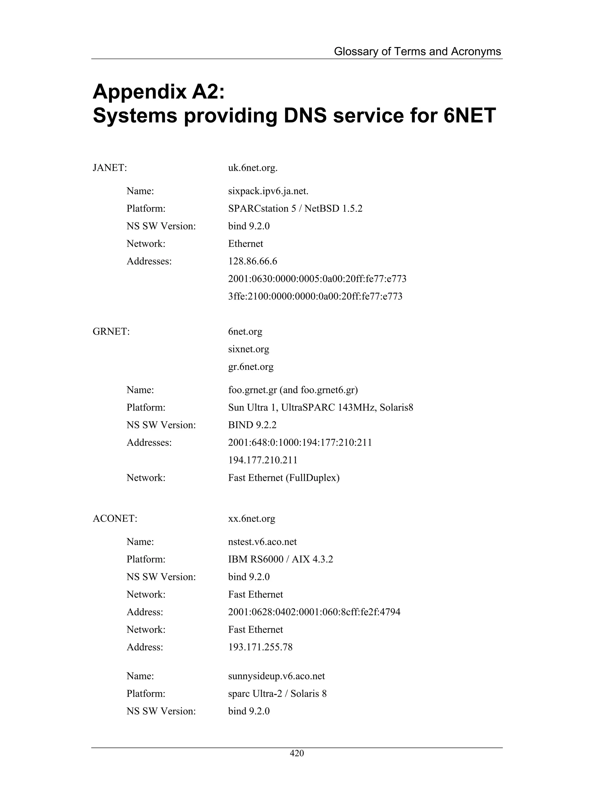
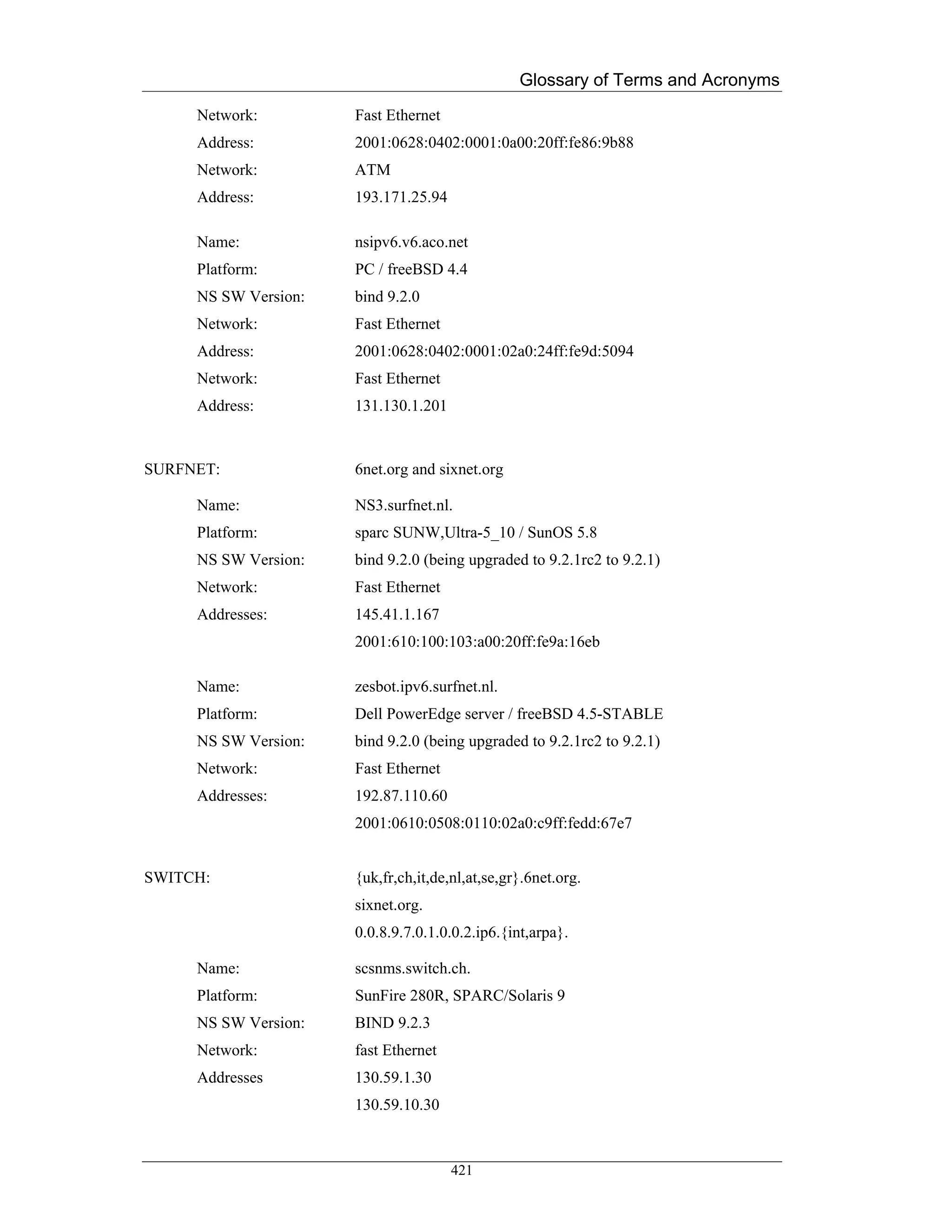
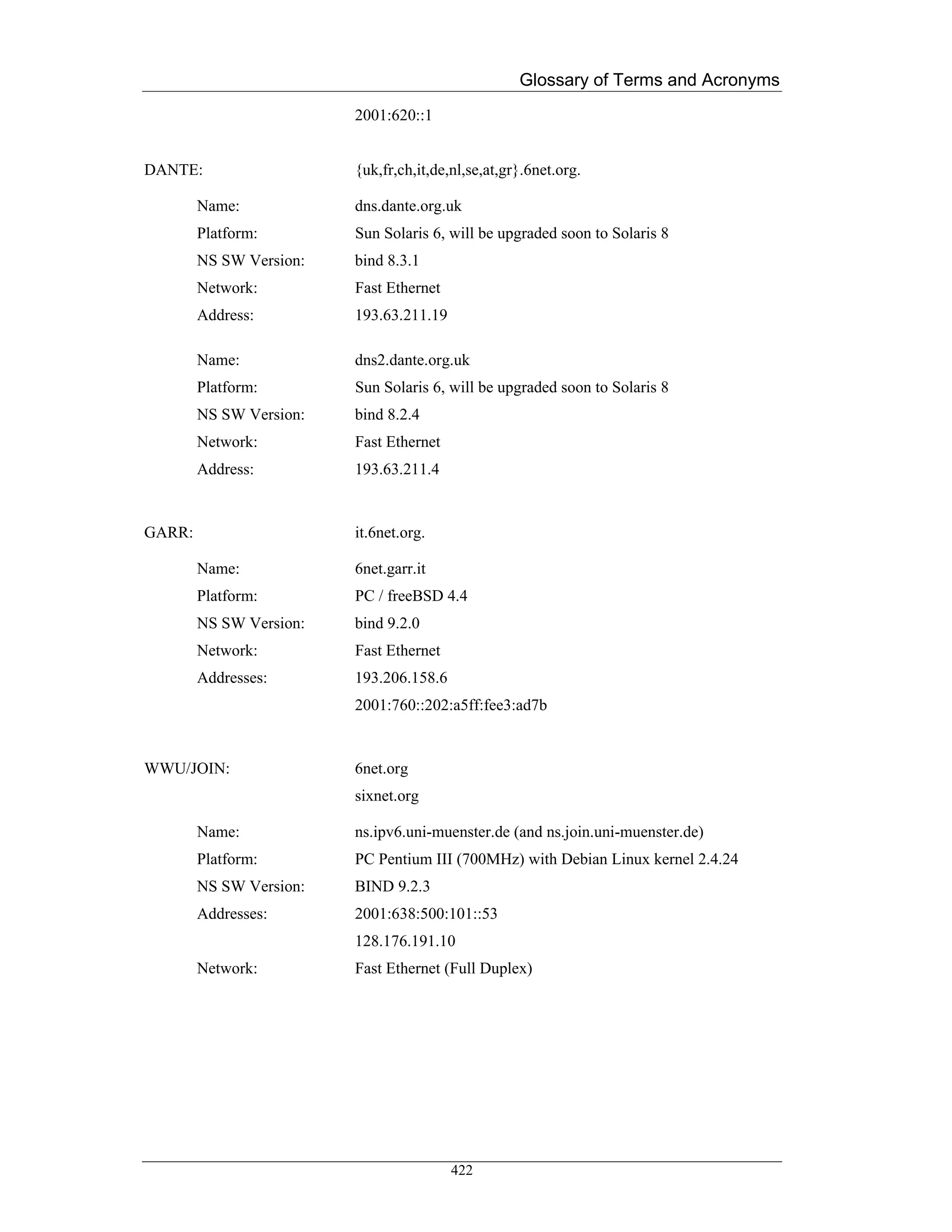
![Glossary of Terms and Acronyms
Appendix B: Enabling IPv6
MS Windows XP
Windows XP embeds IPv6 functionality by default, as the TCP/IP protocols suite includes both
IPv4 Internet Layer and IPv6 Internet Layer. However, Windows XP contains a separate
implemen-tation of TCP and UDP for IPv6.
By typing at the command prompt
# ipv6 install
it will enable and initialize IPv6 functionality on your host. By default, Windows XP
automatically configures the link-local address for each interface that corresponds to installed
Ethernet adapters. Link-local addresses have the prefix FE80::/64. The IPv6 address for each
Ethernet interfaces de-rives from the FE80::/64 prefix and a 64-bit suffix that derives from the
IPv4 plus MAC addresses of the network adapter. For example, a host with IPv4 address
195.225.29.15 and MAC address 00-00-39-3f-7b-90 is assigned the link-local address
fe80::200:39ff:fe3f:7b90. The host is now ready to communicate with other hosts in the same
Ethernet segment.
Windows XP supports stateless address autoconfiguration mode, with which network site-local
addresses, route entries and other configuration parameters are automatically configured based on
the router message advertisements. However, Windows XP hosts may manually be configured
through the network configuration shell “netsh” and following set of commands:
# netsh interface ipv6 {add, set, delete, …} <parameters>
The netsh shell allows the configuration of the IPv6 addresses, the manipulation of the route en-
tries and many other tuning and showing configuration commands. For example, the following
command sets the site local address 2001:648:220::1 to the interface “Local Area Connec-tion”:
# netsh interface IPv6 add address “Local Area Connection” 2001:648:220::1
The complete syntax of the netsh command shell is the following:
# netsh interface IPv6 add address InterfaceNameOrIndex
IPv6Address [[type=] unicast|anycast]
[[validlifetime=]Minutes|infinite] [[preferredlifetime=]
Minutes|infinite][[store=]active|persistent]
423](https://image.slidesharecdn.com/ipv6deployment-guide-110112200202-phpapp01/75/IPv6-Deployment-Guide-437-2048.jpg)