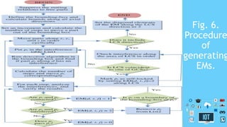
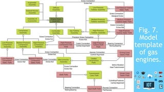
IoT and Cloud Computing
in Automation of
Assembly Modeling
Systems
By : Areej Qasrawi
1
Outline
• Introduction
• goal
• To achieve this goal
• Internet of things (IoT) and manufacturing technologies.
• IoT can be a vital solution
• Distribution of paper sections
2
Introduction
• Companies have to configure themselves to catch new market
opportunities.
• Conventional enterprises with static system architecture, such
as computer-integrated-manufacturing, are no longer able to
cope with high-level complexity and turbulences in a dynamic
environment.
• Many manufacturing paradigms, such as agile manufacturing
,sustainable manufacturing, and IoT have been proposed to
meet these challenges .
3
goal
• In this paper, the challenges in generating assembly plans of complex
products are discussed.
• IoT and cloud computing are proposed to help a conventional assembly
modeling system evolve into an advanced system.
• which is capable to deal with complexity and changes automatically.
4
To achieve this goal
• The proposed system includes the following innovations:
• 1) the modularized architecture to make the system robust, reliable,
flexible, and expandable.
• 2) the integrated object-oriented templates to facilitate interfaces and
reuses of system components.
• 3) the automated algorithms to retrieve relational assembly matrices for
assembly planning.
• Assembly modeling for aircraft engines is used as examples to illustrate
the system effectiveness.
5
Internet of things (IoT) and
manufacturing technologies.
• An interacting network with billions even trillions of the
tracked objects becomes feasible.
• Successful applications of IoT have been demonstrated in
retail business, logistics, military, environment surveillance,
and healthcare .
• In those applications, real-time data can be collected by
numerous sensors and the data can be shared by the network
to support decision-making.
• IoT’s potential in many areas, including design and operation
of manufacturing systems, has yet been explored
systematically.
6
IoT can be a vital solution
• In this paper, IoT is proposed to be applied in automated
assembly planning system.
• IoT can be a vital solution to address system complexity and
uncertainties.
7
The rest of the paper is organized as
follows:
• Section II
• Provides a literature survey on automated assembly modeling to identify the
limitations and challenges of existing techniques.
• Section III
• The object-oriented model template is proposed to address the requirements of
decentralization, modularity, and expandability.
• Section IV
• New data mining algorithms are considered for cloud computing. Automated
algorithms are developed to retrieve relational matrices for assembly modeling.
• Section V
• Assembly modeling for aircraft engines is used as a case study to illustrate the
application of object-oriented product template and algorithms
• Section VI
• The presented work is summarized and the conclusion is provided.
8
II. LITERATURE REVIEW
• The following, enterprise systems (ESs) for assembly modeling and
their correlations with IoT are discussed:
• A. ES for Automated Assembly Modeling:
• Modern products tend to be smarter, more versatile, and sophisticated.
Product structures become even complex, which poses critical challenges in
assembly processes.
• Digital assembly is a type of ESs for assembly planning based on solid
models and structures of products. The level of difficulty of assembly
modeling depends on the complexity of a product, as well as the availability
of data for assembly planning.
• The adoption of IoT in a modeling system will have a significant impact on
these two aspects.
• 1) Complexity.
• 2) Data Availability.
9
Complexity
• ATo quantify the complexity, a system can be viewed as a
constitution of inputs, outputs, and the relational models from
inputs and outputs.
• System complexity relates to the number of system
components, which may be varied significantly from one
system to another.
• Modern products include more and more components and their
production processes involve uncertainties. Both factors
increase system complexity, as well as the complexity of
computer-aided design (CAD) systems
10
Data Availability
• all data and information of the company were integrated that could
be accessed from a centralized database by decision makers.
• The corresponding system paradigm was computer-integrated
manufacturing (CIM).
• CIM could optimize the utilization of system resources to achieve a
high productivity. However, it involved a heavy cost and lacked of
adaptability to accommodate quick changes
• To improve system adaptability, a manufacturing system becomes
dynamic and its boundaries with the environment become vague.
Close interactions are needed in both of inter-enterprise and intra-
enterprise collaborations. Correspondingly, the data required by
decision-making at the high level is decentralized and must be
accessed readily by distributed participators.
11
Data Availability
• scientists have developed various assembly modeling methods,
such as
• map-based relational models, hierarchical tree models, and object-
oriented models.
• Note that in assembly modeling, how to define assembly
relations among parts is critical. As far as assembly relations
are concerned, the examples of the
• relational models are liaison diagram models, AND/OR
Representations , and polychromatic models.
• Among these models, matrices are widely used since they are
efficient to represent the relations and easy to be
programmed.
12
B. IoT and Its Applications
• The advance of an ES relies greatly on IT infrastructure. IoT is
becoming a mainstream infrastructure .
• IoT can help companies to catch emerging opportunities and
improve competitive advantage.
• Cloud computing is a critical technology to support
decisionmaking systems of IoT-based applications .
13
C. IoT for Assembly Modeling
• The challenges of ES for manufacturing enterprises are to achieve system
capability in dealing with the complexity and decentralization of decision-
making activities.
• The enablers of assembly modeling must be modularized, decentralized, and
automated.
• IoT will provide the solution to these challenges. On one hand, the private
cloud or hybrid cloud can be established so that any data can be accessed by
users, no matter how and where the suppliers are geographically distributed.
• Regarding the dynamics of data, IoT links all of the objects together, they are
monitored and real-time data can be collected. Uncertainties can be identified
to support optimized decision-makings.
• accessible distributed tools in IoT are modularized and interoperable. They can
be aggregated to fulfill some complicated decision-makings as needed. As
shown in Fig. 1,
14
Fig. 1.
IoT
application
for
assembly
modeling
and
planning.
15
III. OBJECT-ORIENTED PRODUCT MODEL
TEMPLATES
• The IoT links distributed resources. For example, the CAD models of parts for a
complex product are developed at different places, and assembly modeling and
planning of the product is accomplished at another place.
• It is desirable that the product structure is modularized, so that components in
assembly are loosely coupled.The participators can modify and maintain their
own part models without an unnecessary impact on the general assembly
model.
• An object-oriented model template can meet these requirements
appropriately. An object-oriented model template is also helpful to alleviate
the complexity of product development since less number of interactions will
be involved.
• A model template represents basic elements and their relations of products for
a product family. To facilitate assembly modeling, a model template should
include all required information such as the classes of parts or components,
assembly topologies, options of connections, and assembly plans.
• Fig. 2 shows an example of a model template.
16
Fig. 2.
Model
templa
te of
product
.
17
IV. ALGORITHMS TO AUTOMATE
ASSEMBLY MODELING
• For assembly modeling, the critical tasks are to define the
assembly relations from given product CAD models
automatically.
• In this section, the assembly relations and interference
relations among parts and sub-assemblies are mainly
concerned, and the algorithms to retrieve the matrices for
these relations automatically are proposed.
18
A. Matrix M for Assembly Relations
• A complex product usually consists of many parts and
subassemblies.
• The most important information in a model template for the
product assembly is the connection relations of parts.
• To retrieve it from the model template, a matrix for assembly
relations is defined as follows:
19
20
B. Interference Analysis in Generating
Matrix M
• In defining assembly relations, two parts can be “closed,”
“touched,” or “interfered ” with each other.
• A “closed” relation happens when the distance between two parts
is less than the tooling size.
• A “touched” relation happens when two parts make a physical
contact without interference.
• An “interfered” relation happens when a spatial volume is shared
by two parts.
• For example, a screw and nut should have an interfered relation so
that the fastening works adequately. However, it is critical to
analyze the interference in determining an assembly plan. Fig. 4
shows the process of generating the matrix of assembly relations
with an interference analysis.
21
Fig. 4.
Flowchart
of
generating
the matrix
of assembly
relations.
22
C. Extended Matrix for Assembly Paths
• An extended matrix (EM ) can be defined to include the
directions of assembly or disassembly.
• In defining an EM, every part is positioned with respect to its
local coordinate system (LCS).
• LCS is usually attached on the base feature of the part. It is
desirable that a direction for assembly or disassembly is
coincident with an axis of LCS or global coordinate system
(GCS).
• For example, if a thread is made on an inclined surface, the
assembly direction for a screw should be in line with an axis
perpendicular to the inclined surface.
23
C. Extended Matrix for Assembly Paths
• Therefore, the directions of assembling or disassembling can
be specified either in the GCS or in an LCS.
• Denote the axes of GCS and LCS as (XG ,YG ,ZG ) and (XL ,YL
,ZL ), respectively.
• Available operations of assembly directions for each part
include (-XG ,-YG ,-ZG ,+XG ,+YG ,+ZG ) and (-XL ,-YL ,-ZL ,+XL
,+YL ,+ZL ); where subscripts and represent GCS and LCS,
respectively.
24
C. Extended Matrix for Assembly Paths
• When planning an assembly sequence, parts with a negative
value mean that they have been disassembled to avoid
unnecessary calculation.
• Planning an assembly sequence needs other matrices for other
relations, which can be defined to integrate assembly relation
matrices M’s and EM’s.
• The procedure of the automated generation of EM’s is
depicted in Fig. 6. pi denotes a current part to be analyzed
and pi denotes a part having an assembly relation with pi .
25
Fig. 6.
Procedure
of
generating
EMs.
26
V. CASE STUDY
• To validate the effectiveness of the proposed method,
planning of the assemblies of aircraft engines is used as a case
study.
• Engines are complex products since a typical aircraft engine
has thousands of parts .
• Until now, a standard reference model is not available to the
automated assembly planning. Therefore, a model template in
Fig. 7 is first developed for the assembly planning of the main
bodies of gas engines.
• Note that the template defines basic parts and components,
as well as their assembly relations in the product.
27
Fig. 7.
Model
template
of gas
engines.
28
V. CASE STUDY
• At a high level, an engine is built from three main components:
• compressor section, combustor section, and turbine section.
• Each component can be decomposed into a new level to define the
sub-catalogues of components. For example, a turbine can be
classified according to its working pressure into low-, medium-, or
high-pressure turbine. Any one of turbine includes stators and
shafts. Numerous assembly relations are involved in the template.
• The implemented system is capable of:
• 1) creating assembly plans with the information from solid models,
product data management, and designers’ inputs;
• 2) simulating and visualizing assembly processes;
• 3) evaluating assembling plans.
29
VI. SUMMARY AND CONCLUSION
• The success of ESs in manufacturing applications relies on the
advancement of IT. Decentralization, modularization, and
automation of an ES help to adopt the emerging IoT.
• IoT can be applied to support decision-making at all of domains and
levels of ESs.
• In this paper, an automated system for assembly modeling of
complex products is discussed. To meet new requirements of an ES
built upon IoT infrastructure.
• the advantages of object-oriented methods and product template
methods. It is very appropriate to be applied in a distributed and
decentralized environment.
• The algorithms for the contact and interference relation matrices
have been discussed in details.
30
VI. SUMMARY AND CONCLUSION
• The generation of assembly relation matrices is based on
static interference analysis and the generation of EM is based
on dynamic interference analysis.
• cloud computing is supporting automated assembly modeling
of complex products in a distributed design environment.
• validated the effectiveness of the proposed method, planning
of the assemblies of aircraft engines is used as a case study.
31
THAT'S ALL
THANK YOU ☺
32

IoT and Cloud Computing in Automation Application

  • 1.
    IoT and CloudComputing in Automation of Assembly Modeling Systems By : Areej Qasrawi 1
  • 2.
    Outline • Introduction • goal •To achieve this goal • Internet of things (IoT) and manufacturing technologies. • IoT can be a vital solution • Distribution of paper sections 2
  • 3.
    Introduction • Companies haveto configure themselves to catch new market opportunities. • Conventional enterprises with static system architecture, such as computer-integrated-manufacturing, are no longer able to cope with high-level complexity and turbulences in a dynamic environment. • Many manufacturing paradigms, such as agile manufacturing ,sustainable manufacturing, and IoT have been proposed to meet these challenges . 3
  • 4.
    goal • In thispaper, the challenges in generating assembly plans of complex products are discussed. • IoT and cloud computing are proposed to help a conventional assembly modeling system evolve into an advanced system. • which is capable to deal with complexity and changes automatically. 4
  • 5.
    To achieve thisgoal • The proposed system includes the following innovations: • 1) the modularized architecture to make the system robust, reliable, flexible, and expandable. • 2) the integrated object-oriented templates to facilitate interfaces and reuses of system components. • 3) the automated algorithms to retrieve relational assembly matrices for assembly planning. • Assembly modeling for aircraft engines is used as examples to illustrate the system effectiveness. 5
  • 6.
    Internet of things(IoT) and manufacturing technologies. • An interacting network with billions even trillions of the tracked objects becomes feasible. • Successful applications of IoT have been demonstrated in retail business, logistics, military, environment surveillance, and healthcare . • In those applications, real-time data can be collected by numerous sensors and the data can be shared by the network to support decision-making. • IoT’s potential in many areas, including design and operation of manufacturing systems, has yet been explored systematically. 6
  • 7.
    IoT can bea vital solution • In this paper, IoT is proposed to be applied in automated assembly planning system. • IoT can be a vital solution to address system complexity and uncertainties. 7
  • 8.
    The rest ofthe paper is organized as follows: • Section II • Provides a literature survey on automated assembly modeling to identify the limitations and challenges of existing techniques. • Section III • The object-oriented model template is proposed to address the requirements of decentralization, modularity, and expandability. • Section IV • New data mining algorithms are considered for cloud computing. Automated algorithms are developed to retrieve relational matrices for assembly modeling. • Section V • Assembly modeling for aircraft engines is used as a case study to illustrate the application of object-oriented product template and algorithms • Section VI • The presented work is summarized and the conclusion is provided. 8
  • 9.
    II. LITERATURE REVIEW •The following, enterprise systems (ESs) for assembly modeling and their correlations with IoT are discussed: • A. ES for Automated Assembly Modeling: • Modern products tend to be smarter, more versatile, and sophisticated. Product structures become even complex, which poses critical challenges in assembly processes. • Digital assembly is a type of ESs for assembly planning based on solid models and structures of products. The level of difficulty of assembly modeling depends on the complexity of a product, as well as the availability of data for assembly planning. • The adoption of IoT in a modeling system will have a significant impact on these two aspects. • 1) Complexity. • 2) Data Availability. 9
  • 10.
    Complexity • ATo quantifythe complexity, a system can be viewed as a constitution of inputs, outputs, and the relational models from inputs and outputs. • System complexity relates to the number of system components, which may be varied significantly from one system to another. • Modern products include more and more components and their production processes involve uncertainties. Both factors increase system complexity, as well as the complexity of computer-aided design (CAD) systems 10
  • 11.
    Data Availability • alldata and information of the company were integrated that could be accessed from a centralized database by decision makers. • The corresponding system paradigm was computer-integrated manufacturing (CIM). • CIM could optimize the utilization of system resources to achieve a high productivity. However, it involved a heavy cost and lacked of adaptability to accommodate quick changes • To improve system adaptability, a manufacturing system becomes dynamic and its boundaries with the environment become vague. Close interactions are needed in both of inter-enterprise and intra- enterprise collaborations. Correspondingly, the data required by decision-making at the high level is decentralized and must be accessed readily by distributed participators. 11
  • 12.
    Data Availability • scientistshave developed various assembly modeling methods, such as • map-based relational models, hierarchical tree models, and object- oriented models. • Note that in assembly modeling, how to define assembly relations among parts is critical. As far as assembly relations are concerned, the examples of the • relational models are liaison diagram models, AND/OR Representations , and polychromatic models. • Among these models, matrices are widely used since they are efficient to represent the relations and easy to be programmed. 12
  • 13.
    B. IoT andIts Applications • The advance of an ES relies greatly on IT infrastructure. IoT is becoming a mainstream infrastructure . • IoT can help companies to catch emerging opportunities and improve competitive advantage. • Cloud computing is a critical technology to support decisionmaking systems of IoT-based applications . 13
  • 14.
    C. IoT forAssembly Modeling • The challenges of ES for manufacturing enterprises are to achieve system capability in dealing with the complexity and decentralization of decision- making activities. • The enablers of assembly modeling must be modularized, decentralized, and automated. • IoT will provide the solution to these challenges. On one hand, the private cloud or hybrid cloud can be established so that any data can be accessed by users, no matter how and where the suppliers are geographically distributed. • Regarding the dynamics of data, IoT links all of the objects together, they are monitored and real-time data can be collected. Uncertainties can be identified to support optimized decision-makings. • accessible distributed tools in IoT are modularized and interoperable. They can be aggregated to fulfill some complicated decision-makings as needed. As shown in Fig. 1, 14
  • 15.
  • 16.
    III. OBJECT-ORIENTED PRODUCTMODEL TEMPLATES • The IoT links distributed resources. For example, the CAD models of parts for a complex product are developed at different places, and assembly modeling and planning of the product is accomplished at another place. • It is desirable that the product structure is modularized, so that components in assembly are loosely coupled.The participators can modify and maintain their own part models without an unnecessary impact on the general assembly model. • An object-oriented model template can meet these requirements appropriately. An object-oriented model template is also helpful to alleviate the complexity of product development since less number of interactions will be involved. • A model template represents basic elements and their relations of products for a product family. To facilitate assembly modeling, a model template should include all required information such as the classes of parts or components, assembly topologies, options of connections, and assembly plans. • Fig. 2 shows an example of a model template. 16
  • 17.
  • 18.
    IV. ALGORITHMS TOAUTOMATE ASSEMBLY MODELING • For assembly modeling, the critical tasks are to define the assembly relations from given product CAD models automatically. • In this section, the assembly relations and interference relations among parts and sub-assemblies are mainly concerned, and the algorithms to retrieve the matrices for these relations automatically are proposed. 18
  • 19.
    A. Matrix Mfor Assembly Relations • A complex product usually consists of many parts and subassemblies. • The most important information in a model template for the product assembly is the connection relations of parts. • To retrieve it from the model template, a matrix for assembly relations is defined as follows: 19
  • 20.
  • 21.
    B. Interference Analysisin Generating Matrix M • In defining assembly relations, two parts can be “closed,” “touched,” or “interfered ” with each other. • A “closed” relation happens when the distance between two parts is less than the tooling size. • A “touched” relation happens when two parts make a physical contact without interference. • An “interfered” relation happens when a spatial volume is shared by two parts. • For example, a screw and nut should have an interfered relation so that the fastening works adequately. However, it is critical to analyze the interference in determining an assembly plan. Fig. 4 shows the process of generating the matrix of assembly relations with an interference analysis. 21
  • 22.
  • 23.
    C. Extended Matrixfor Assembly Paths • An extended matrix (EM ) can be defined to include the directions of assembly or disassembly. • In defining an EM, every part is positioned with respect to its local coordinate system (LCS). • LCS is usually attached on the base feature of the part. It is desirable that a direction for assembly or disassembly is coincident with an axis of LCS or global coordinate system (GCS). • For example, if a thread is made on an inclined surface, the assembly direction for a screw should be in line with an axis perpendicular to the inclined surface. 23
  • 24.
    C. Extended Matrixfor Assembly Paths • Therefore, the directions of assembling or disassembling can be specified either in the GCS or in an LCS. • Denote the axes of GCS and LCS as (XG ,YG ,ZG ) and (XL ,YL ,ZL ), respectively. • Available operations of assembly directions for each part include (-XG ,-YG ,-ZG ,+XG ,+YG ,+ZG ) and (-XL ,-YL ,-ZL ,+XL ,+YL ,+ZL ); where subscripts and represent GCS and LCS, respectively. 24
  • 25.
    C. Extended Matrixfor Assembly Paths • When planning an assembly sequence, parts with a negative value mean that they have been disassembled to avoid unnecessary calculation. • Planning an assembly sequence needs other matrices for other relations, which can be defined to integrate assembly relation matrices M’s and EM’s. • The procedure of the automated generation of EM’s is depicted in Fig. 6. pi denotes a current part to be analyzed and pi denotes a part having an assembly relation with pi . 25
  • 26.
  • 27.
    V. CASE STUDY •To validate the effectiveness of the proposed method, planning of the assemblies of aircraft engines is used as a case study. • Engines are complex products since a typical aircraft engine has thousands of parts . • Until now, a standard reference model is not available to the automated assembly planning. Therefore, a model template in Fig. 7 is first developed for the assembly planning of the main bodies of gas engines. • Note that the template defines basic parts and components, as well as their assembly relations in the product. 27
  • 28.
  • 29.
    V. CASE STUDY •At a high level, an engine is built from three main components: • compressor section, combustor section, and turbine section. • Each component can be decomposed into a new level to define the sub-catalogues of components. For example, a turbine can be classified according to its working pressure into low-, medium-, or high-pressure turbine. Any one of turbine includes stators and shafts. Numerous assembly relations are involved in the template. • The implemented system is capable of: • 1) creating assembly plans with the information from solid models, product data management, and designers’ inputs; • 2) simulating and visualizing assembly processes; • 3) evaluating assembling plans. 29
  • 30.
    VI. SUMMARY ANDCONCLUSION • The success of ESs in manufacturing applications relies on the advancement of IT. Decentralization, modularization, and automation of an ES help to adopt the emerging IoT. • IoT can be applied to support decision-making at all of domains and levels of ESs. • In this paper, an automated system for assembly modeling of complex products is discussed. To meet new requirements of an ES built upon IoT infrastructure. • the advantages of object-oriented methods and product template methods. It is very appropriate to be applied in a distributed and decentralized environment. • The algorithms for the contact and interference relation matrices have been discussed in details. 30
  • 31.
    VI. SUMMARY ANDCONCLUSION • The generation of assembly relation matrices is based on static interference analysis and the generation of EM is based on dynamic interference analysis. • cloud computing is supporting automated assembly modeling of complex products in a distributed design environment. • validated the effectiveness of the proposed method, planning of the assemblies of aircraft engines is used as a case study. 31
  • 32.