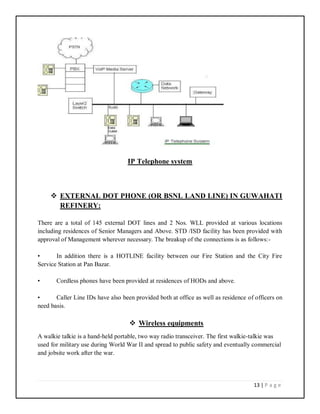
SlideShare a Scribd company logo
SUMMER TRAINING REPORT
Indian Oil Corporation Limited, Guwahati Refinery
Duration: 15.06.2019 – 14.07.2019
Submitted by:
Dhurba Jyoti Boruah (1604168)
In partial fulfilment for awarding the degree of
BACHELOR OF TECHNOLOGY
IN
ELECTRONICS AND COMMUNICATION ENGINEERING
SCHOOL OF ENGINEERING AND TECHNOLOGY
NAGALAND UNIVERSITY
PREFACE
Industrial training plays a vital role in the progress of future engineers. Not only does it provide
insights about the future concerned, it also bridges the gap between theory and practical
knowledge. I was fortunate that I was provided with an opportunity of undergoing industrial
training at INDIAN OIL CORPORATION LTD, Guwahati Refinery. The experience gained
during this short period was fascinating to say the least. It was a tremendous feeling to observe
the operation of different units and processes. It was overwhelming for us to notice how such a
big refinery is being monitored and operated with proper coordination to achieve desired results.
During my training I realized that in order to be a successful engineer one needs to put his/her
concepts into action. Thus, I hope that this training serves as a stepping stone for me in future
and help me carve a niche for myself in this field.
ACKNOWLEDGEMENT
My indebtedness and gratitude to the many individuals who have helped to shape
this report in its present form cannot be adequately conveyed in just a few
sentences. Yet I must record my immense gratitude to those who helped me
undergo this valuable learning at IOCL ,Guwahati Refinery.
I am highly obliged to Training and Development Department of our university for
providing me this opportunity to learn at IOCL.
We would like to thank Mr. O.P Chetry,DGM and Mr. Suraj Kumar ( F&S) for
briefing us on orientation and their helpful words on fire and safety.
Our sincere gratitude goes to Mr. Aditya Jaiswal, AssistanceManager (Electrical)
and Mr. Amit Kumar Gupta (instrumentation Engineer) for their valuable
guidance.
Last but not the least, we are grateful to everyone who guided us in the field work.
CERTIFICATION
This is to certify that DHURBA JYOTI BORUAH, from School of Engineering & Technology,
Nagaland University has performed summer internship training for the specified number of days
under my guidance and supervision.
Mr. Aditya Jaiswal Amit Kumar Gupta
Assistant Manager (Communication Section) Instrumentation Engineer
CONTENTS
 Introduction to Guwahati Refinery……………………………………..1
 Fire and Safety …………………………………………….…..4
 Communication Systems………………………………………………...7-29
 Communication Facilities………………………………...…....7
 Epabx Telephone System………………………………………7
 Wintap/ARP System……………………………………..……..9
 Network Termination Unit…………………………………..…10
 Main Frame Distribution(MDF)/Krone………………………..11
 External Dot Lines…………………………………………......13
 Wireles sequipments………………………………………..….13
• Walkie-talkie……………………………………….…14
• Base Station………………………………….……….19
 Plant Communication System…………………………...……..23
 Fire Alarm………………………………………………...……25
 Different Types of Detectors………………………….………..26
 Sirens……………………………………………….………......28
 Instruments Used in Refinery for Parameter Management………..........30-41
 Pressure measuring devices……………………………… ...….31
 Flow Measuring Instruments………………………………………….…….…32
 Temperature Measuring Instruments………………………………….….33
 Level Measuring Instrument…………………………….…..…37
 Delayed Coker Unit (DCU)………………………………...……….42
 Conclusion …………………………………………….......44
1 | P a g e
TOPIC 1:-Introduction to Guwahati Refinery
Guwahati Refinery is the country's first Public Sector Refinery as well as IndianOil's first
Refinery serving the nation since 1962. Built with Rumanian assistance, the initial crude
processing capacity at the time of commissioning of this Refinery was 0.75 MMTPA and
the Refinery was designed to process indigenous Assam Crude. The refining capacity
was subsequently enhanced to 1.0 MMTPA. Due to dwindling supply of indigenous
Assam Crude, Guwahati Refinery started processing Low Sulfur Imported Crude along
with Assam Crude. The supply of LS imported crude to Guwahati Refinery is from
Barauni Refinery via railway wagons.
The Refinery supplies various petroleum products to Northeastern India as well as
beyond, upto Siliguri end through the Guwahati-Siliguri Pipeline, spanning 435 KM,
which was the first Pipeline of IndianOil and commissioned in 1964. Most of the
products of Guwahati Refinery are evacuated through pipeline and some quantity also
through road transportation.
LPG, Naphtha, Motor Spirit (MS), Aviation Turbine Fuel, Superior Kerosene Oil, High
Speed Diesel (HSD), Raw Petroleum Coke and Sulfur are the products of this Refinery.
Auto fuels MS and HSD supplied by the refinery are of eco-friendly BS-IV grade as per
statutory guidelines of Government of India. The production of these valuable petroleum
products is through a series of different primary and secondary processing units along
with the associated auxiliary facilities like Captive Power Plant installed within the
refinery.
In the primary unit of the Refinery i.e. the Crude Distillation Unit (CDU), desalted crude
from the desalter is heated up through a series of heat exchangers and is fed into a pre
fractionator column. Here the lighter gases, LPG and unstabilised gasoline are separated.
The outputs from CDU are gasoline, Kero-I, Kero-II and Straight Run Gas Oil. Reduced
Coke Oil (RCO) which is the bottom product from the main fractionating column, forms
the main raw material for Coking unit and Indmax. In Naphtha Splitter section, total
Straight Run Naphtha is separated into three different fractions namely Light Naphtha
(LN), Reformate Naptha (RN) and Heavy Naptha (HN).
Delayed Coking Unit (DCU) with a capacity of 0.44 MMTPA is the main secondary unit
of Guwahati Refinery. The unit produces middle distillates from heavy ends. Main
feedstock to DCU is Reduced Crude Oil, which is heated to high temperatures of about
500oC in a furnace. Due to high temperatures, RCO is thermallycracked and yields
various hydrocarbon fractions like LPG, coker gasoline, coker kerosene, coker gas oil,
coker fuel oil, residual fuel oil and coke.
2 | P a g e
INDMAX unit, in-house technology developed by R&D Centre of IndianOil was
installed for increased production of LPG and gasoline from heavy ends like Reduced
Crude Oil and Coker Fuel Oil. Indmax unit works on the Fluidized Catalytic Cracking
process similar to other Fluidised Catalytic Cracking Units. The first commercial unit
based on INDMAX technology was installed at Guwahati Refinery with a capacity of 0.1
MMTPA, and the capacity was subsequently enhanced to 0.15 MMTPA. Besides its
function of maximization of LPG, it enables the Refinery to upgrade its residual products
to high value distillate products.
Hydrotreating Unit with a capacity of 0.6 MMTPA produces High Speed Diesel (HSD),
Aviation Turbine Fuel (ATF) and Pipeline Compliant Kerosene (PCK) in blocked out
mode of operation. In HSD mode of operation, Sulfur content of diesel components ex
CDU, DCU and Indmax unit is removed and Cetane number is boosted. Smoke point of
Straight Run Kerosene component is improved in ATF and PCK modes along with
desulfurization. Hydrogen required for Hydrotreating is produced in Hydrogen
Generation Unit based on Steam Reforming technology.
Isomerization unit (45 TMTPA) produces MS component by improving Research Octane
Number upto 87.0 units and also helps in meeting the Benzene content specification of
MS.
INDAdept unit (35 TMTPA , developed by IOCL-R&D and EIL, removes Sulfur content
from Heavy Cut of Indmax gasoline to < 50 ppm to meet the Sulfur specification of BS-
VI quality MS.
The Sulphur Recovery Unit (5 TPD) in the Refinery takes care of the sour off gases from
the various units for removal of Hydrogen Sulphide. This is done by Amine treatment
after which H2S is converted to sulphur through Claus process.
Guwahati Refinery is amongst those Indian Refineries who have standardized their
various systems and has been awarded with ISO-9001 for Quality Management, ISO-
14001 for Environment management, OHSAS-18001 for Occupational Health and Safety
and ISO-27001 for Information Security management. Guwahati Refinery has also been
3 | P a g e
certified with the ISO-50001 certification in recognition of its sincere efforts to manage
its energy usage in an efficient manner. Guwahati Refinery is also known for its sincere
efforts on development as well as implementation of effective Safety, Health &
Environment management systems and procedures along with good performance in
occupational health and safety.
4 | P a g e
TOPIC 2:-
FIRE AND SAFETY
There are several types of fires, and also several ways to put them out. The three main fire
suppressants used are water, foam, and dry chemicals, and knowing their qualities can help you
optimize your firefighting abilities.
Water
Water has been the most popular fire suppressant throughout history, and can be useful in
fighting class A fires (fires made up of common combustible solids). Water is ineffective at
suppressing oil and electrical fires (Class B and C fires), and can actually be dangerous if used
on either. Water is also used to be mixed with firefighting foam and those class A fires are very
common, so water will likely continue to be a large part of fire suppression in the future.
Firefighting Foam
Firefighting foam was invented in the early 1900’s, and has evolved into various forms for
different types of fires. Type A foam was originally made for use against forest fires and is used
similarly to water. Type B foam is meant for liquid spills, and ARFF foam falls under this
category. ARFF foam has a low viscosity, and is able to cover large amounts of spilled jet fuel in
a short time period. Foam allows you to coat the materials that are burning, and then cut off the
oxygen to help suppress the fire.
Dry Chemicals
There are also various types of dry chemicals that are made for different purposes. Some of the
most popular are ABC chemical, Purple-K, and BC chemical. The ABC chemical is the most
versatile, and can be used to suppress all types of fires. Purple-K is useful when fighting liquid
fires.
Dry chemicals are frequently used in industrial settings, where chemical and electrical fires are at
a high risk. Dry chemicals are only used when needed due to the fine particulates that spread
easily over a large area and create a cleanup nightmare.
5 | P a g e
Carbon Dioxide
Carbon dioxide removes oxygen to stop a fire but has limited range. It is environmentally
friendly and leaves no residue, so cleanup is unnecessary. Extinguishers with carbon dioxide are
usually used in contamination-sensitive places such as computer rooms, labs, food storage areas,
processing plants, etc.
Knowing which agent to use when fighting fires is important for everyone, not just firefighters.
Making the wrong selection could cause serious problems, so it’s important to do your research
first. Careful research and training will allow you to fight fires in the most effective manner
possible.
6 | P a g e
TOPIC 3:- COMMUNICATION SYSTEMS
 COMMUNICATION FACILITIES
 EPABX TELEPHONE SYSTEM
 WINTAP/ARP SYSTEM
 NETWORK TERMINATION UNIT
 EXTERNAL DOT LINES
 MAIN FRAME DISTRIBUTION(MDF)/KRONE
 TELEPHONE
7 | P a g e
COMMUNICATION FACILITIES
The various communication facilities available at Guwahati Refinery are:
1. Plant communication system (paging system)
2. Walkie-Talkie (wireless) system
3. Loud speaker announcing system
4. EPABX Telephone system
5. External DOT phones
6. Mobile /Cellular Phones
7. Fire Alarm Systems
8. Air Raid Protection (ARP) system
9. Group SMS Broadcasting system
10. Sirens
 EPABX TELEPHONE SYSTEM:
A private branch exchange (PBX) is a telephone exchange that serves a particular
business or office, as opposed to one that a common carrier or telephone company
operates for many businesses or for the general public. PBXs are referred to as:
 PABX: Private automatic branch exchange.
 EPAB: Electronic private automatic branch exchange.
EPABX stands for electronic private automatic branch exchange. The EPABX system
installed at the Guwahati Refinery is known as communication-6(CM-6). CM-6 is of
1484 lines and is installed at the Administrative building of Refinery equipped with the
Level DID (Direct Inward Dialling) facility.
The system is in operation with 57 junction lines provided for “0” dialling facility
provided for selected EPABX numbers and 2 Mbps stream(30circuits) for incoming level
DID facility.
8 | P a g e
The communication between the exchanges is maintained by the tie-lines. The 2 MB
telephone line from E-10-B Panbazar Exchange (main exchange of Guwahati) is
connected to the Refinery EPABX via the NOONMATI RLU (Remote Line Unit) which
is a child exchange helping in distribution.
The number of various departments of the refinery consists of four digit numbers starting
from 7000 to 7999. A 259 code has been allotted to the IOCL by the city telephone
neglects the first two digits and sets the line to the telephone number specified. For
quarters telephone no starts from 8000 to 8999.
There are 12 internal hotlines provided to the plants in between control room to field
plants. Another line is at the MDF for checking the connection line pair.
The EPABX servers should provide the following features as a part of its telephone
functions:
 Call coverage: Minimum 5 independent coverage paths for various
incoming calls.
 Authorization code: 5 to 7 digit authorization code to make outgoing
calls thereby ensuring no misuse of the system.
 Call pickup: Call pickup within the group as well as outside group.
 Account codes: It should be possible to enter account codes before or
during a call. Users may be forced to enter account codes based upon their
class of service.
 Call Forwarding: Any extension should be able to transfer all incoming
calls temporarily to another pre-selected extension. Such request shall be
registered by dialling a code followed by the extension number. Facility
also exists of cancellation of a request registered earlier. This facility
should be available throughout a network.
 Call Transfer: Any extension user must be able to transfer call to another
extension without the help of attendant.
 Call Diverting: On busy, On No Response, after specific specifics
number of rings, etc.
 Call Bridging: Bridging calls from extension to cell phones.
9 | P a g e
For the operation of some of the above mentioned functions, some software used in
exchange on Guwahati Refinery are as follows:
 WINTAP
 AIR RAID PROTECTION
(Emergency management software)
 WINTAP:
EPBAX should be provided the system tariff report. Tariff statistics should be
provided on incoming and outgoing trunk groups, attendant consoles, station hunt
groups, and individual stations. The information must include the number of calls
and call duration.
WINTAP is software which is used for monitoring and recording all the incoming
and outgoing calls, that is used for monitoring the call tariff. This software
provides all the information about call rates, call duration, incoming and outgoing
calls, STD or LOCAL calls or within the intercom.
 AIR RAID PROTECTION (ARP):
Air raid protection is an emergency management system. This is used in
emergency situation like fire in refinery. In case of emergency situation the “FIRE
AND SAFETY DEPT” record and store the emergency message 5 times by
bailing the 139 through the intercom and then the emergency management system
conveys the message to all the DGMs, HODs at the same time. After receiving the
message they have to rush to the place where the emergency has occurred. This
system is regarded as Air Raid Protection. The emergency software monitors this
ARP system. This software reports the success or failure of the ARP system. This
software is developed by VOICE-GATE.
ARP in Guwahati Refinery in brief points is as follows:
 It provides simultaneous ring to 24 telephone subscribers.
 It covers 24 numbers to the EPABX exchange.
 This system can be activated from fire stations control room through the
auto-telephone number by bailing 139.
 The caller has to make his message loud and distinct and repeat it several
times for about 15 to 20 seconds.
10 | P a g e
 This is one directional communication. The subscriber of that respective
numbers can only hear the message, but cannot answer back.
The various classes of Restriction (COR) facilities in Refinery exchange are
as follows:
 COR 1:Non-Zero dial.
 COR 2: Zero dial with less frequency.
 COR 3: Zero dial with high frequency.
 COR 4: COR 3 with local dial.
 COR 5: COR 4 with STD.
 COR 6: COR 5 with high frequency.
 NETWORK TERMINATION UNIT (NTU):
A network termination unit (NTU) is a device that links the customer-premises equipment (CPE)
to the public switched telephone network (PSTN). The device serves as the last point of
connection between the two. Typically, the service provider is the owner of the NTU, which
usually supports various communication standards, including protocols and voltages, to allow
different device types to communicate with the PSTN.
The Guwahati Refinery exchange has a direct link with the BSNL exchange, Panbazar through
fibre optic cables. So it requires a remote NTU for this purpose. The Refinery exchange uses a
modem as per the convenience. Ti is a stand-alone HDSL NTU/LTU that enables the
transmission of 2048 kbps E1 data streams over a pair of unconditioned twisted pair lines, using
the High Bit Rate Digital Subscriber Line(HDSL) technology.
Network termination unit
11 | P a g e
 MAIN DISTRIBUTION FRAME:
In telephony, a main distribution frame (MDF or main frame) is a signal distribution frame for
connecting equipment (inside plant) to cables and subscriber carrier equipment (outside plant).
The MDF is a termination point within the local telephone exchange where exchange equipment
and terminations of local loops are connected by jumper wires at the MDF. All cable copper
pairs supplying services through user telephone lines are terminated at the MDF and distributed
through the MDF to equipment within the local exchange e.g. repeaters and DSLAM. Cables to
intermediate distribution frames (IDF) terminate at the MDF. Trunk cables may terminate on the
same MDF or on a separate trunk main distribution frame (TMDF).
The most common kind of large MDF is a long steel rack accessible from both sides. On one
side, termination blocks are arranged horizontally at the front of rack shelves. Jumpers lie on the
shelves and go through an insulated steel hoop to run vertically to other termination blocks that
are arranged vertically.
With disciplined administration the MDF can hold over a hundred thousand jumpers, with
dozens changed every day, for decades without tangling.
MDF (Main Distribution Frame)
 KRONE:
12 | P a g e
The Krone connection system is a reliable and cost effective technique for installation of
communications, broadcast and data wiring and has several advantages over solder tag methods,
including significant time and maintenance and benefits .Krone offers a comprehensive range of
connections and wiring system, based on a standard 10 pair (unscreened) termination module.
There is a complementary range of accessories for testing alternative equipment termination,
cable distribution and jumping. Krone uses an insulation displacement connection which totally
eliminates the need to strip, solder or screw connect wires.
Connections are made using KRONE INSERTION TOOL on a slot in the module. The slot
contains wire clamping ribs and two flexible metal contact arms at 45 degrees. These cut the
wire insulation and into the conductor, maintaining contact with spring force. A gas tight seal is
formed between the conductor and contact.
10 pair krone module
10 pair disconnection module
This is the most popular module used for audio and communications. It can be used for
termination of unscreened pair cable or for screened audio cable where the screen either common
terminates or floats at this connection point.
POWER SUPPLY FOR EPABX:
The EPABX requires 48V/40A DC supply. So an AC to DC converter is there which converts
the 3 phase AC supply to 48V DC supply. In case the main fails, the power back-up is given by
the 24 cell battery which can give power backup of about 8 hours.
13 | P a g e
IP Telephone system
 EXTERNAL DOT PHONE (OR BSNL LAND LINE) IN GUWAHATI
REFINERY:
There are a total of 145 external DOT lines and 2 Nos. WLL provided at various locations
including residences of Senior Managers and Above. STD /ISD facility has been provided with
approval of Management wherever necessary. The breakup of the connections is as follows:-
• In addition there is a HOTLINE facility between our Fire Station and the City Fire
Service Station at Pan Bazar.
• Cordless phones have been provided at residences of HODs and above.
• Caller Line IDs have also been provided both at office as well as residence of officers on
need basis.
 Wireless equipments
A walkie talkie is a hand-held portable, two way radio transceiver. The first walkie-talkie was
used for military use during World War II and spread to public safety and eventually commercial
and jobsite work after the war.
14 | P a g e
The major characteristics include a half duplex channel (only one radio transmits at a time
though any number can listen) and a push to talk switch that starts transmission. Typical walkie-
talkie resembles a telephone handset, possibly slightly larger but still a single unit, with an
antenna sticking out on the top. Where a phone’s earpiece is only loud enough to be heard by the
user, walkie-talkie’s built in speaker can be heard by the user and those in the immediate
vicinity.
Conventionally known as Public Mobile Radio Trunking Services (PMRTS), it allows a group of
people to communicate with each other, even if some or all of them are on the move.
ADVANTAGES OF PMRTS OVER CONVENTIONAL RADIOS:
1) Shares equipments such as repeaters in a more effective and cost efficient manner.
2) Increases probability of obtaining free channels, less waiting time and improved
productivity.
3) Improves privacy of communication
4) Efficient use of spectrum
5) Eliminates the need to monitor channel before transmitting.
 ADVANTAGES OF Wireless equipments:
1) Push to talk button (PTT): Instant communication at the push of a button.
2) Unlimited group size for conferencing with private call facility.
3) Clutter-free, city wide coverage.
4) No scope for misuse and external distraction.
5) Mission critical messaging facility, both group and one to one.
6) Unlimited talk time at low fixed call.
7) Best suited for emergency response and crisis management
8) No waiting, no dialling, no network congestion
9) Total command and control: Management by listening in.
CLASSIFICATION OF WALKIE-TALKIE:
1) Fixed Walkie-Talkie:
Walkies positioned at a central site like an office or headquarters where the manager can
maintain contact with the field staff. The equipment at such a site is termed as base
Station.
2) Mobile Walkie-Talkie: Walkies installed in vehicles are referred to as Mobile Walkie.
3) Portable Walkie Talkie:
15 | P a g e
Walkies small enough to be carried around in hand are referred to as Portable Walkie
talkies.
ADVANTAGES OF DIGITAL WALKIE TALKIE OVER ANALOG
WALKIE TALKIE:
Walkie-talkie sets are in use in Refineries for communication purpose. Digital wireless
equipment’s are more advantageous than analog one. Noise reduction & clear voice is the
basic advantage of digital walkie talkie over analog one. Simultaneous talking paths (i.e.
2 groups can communicate using one repeater), unit ID, status buttons, text messages,
GPS tracking, Frequency management are some of the additional advantages of Digital
Walkie talkie which is absent in analog type of walkie talkie.
Operating instruction for Digital walkie talkie set
16 | P a g e
Channel Number Allocated to
1 Channel 1
2 Channel 2
3 Channel 3
4 Channel 4
5 Channel 5
6 Channel 6
7 Channel 7
8 Channel 8
9 Channel 9
10 Channel 10
Operating instruction for Digital walkie talkie sets
 Walkie talkie can be turn on/turn off by using Volume Control switch & adjust its
volume level.
 Select desired channel by channel selector switch.
17 | P a g e
 During giving message, Ensure Push to talk (PTT) button remains properly pressed. An
indicating LED just near channel selection switch will glow, if PTT is pressed.
 When we press PTT button, there is a beep sound. Message to be given after beep sound
only.
18 | P a g e
 For receiving message, Ensure Push to talk (PTT) button is released.
 Use of P1 & P2: P1 for Check the ID of the handset; P2 for Contacts.
Do’s and Don'ts
 Press the PTT Button and speak clearly about 2.5 to 5 cm (one to two inches) away from
the microphone.
 All users are advised to press PTT (Push to talk) button only during the time of
transmitting message and will be kept free for rest of the time.
 Keep your conversation brief and to the point and make use of word “OVER” after
completion of message.
 Do not put the set on charger when battery is charged. Walkie Talkie set should be put on
charger only when battery is discharged.
 If the charged walkie talkie is put on charger, it will reduce the life of battery and will
create problem in the set.
19 | P a g e
Procedure of sending message using Digital walkie talkie sets
Message can be sent to One group, All groups or any particular set (or ID) from a digital
walkie talkie set to another digital walkie talkie set, when it is in digital channel (All channel
except channel no: 2).
Procedure is as follows:
1) Go to the desired channel, to which message is to be given.
2) Press OK
3) Move the highlighted beam to message with UP/DOWN button
4) Press OK.
 Move highlighted cursor to compose and press ok.
 Type message using alphanumeric key and press ok.
OR
 Move highlighted cursor to quick text and press ok
 Select relevant quick text message and press ok.
5)
 How to send message to One group or All groups:Select the group and sent the
message
 How to send message to any particular set (or ID):Select the manual dial, enter the ID
of particular set and press ok.
 BASE STATION:
Base station systems are used to provide instantaneous one-to-one or one-to-many
communication. Base station can be on the form of stationary base stations or they can be
mounted on moving vehicles for maximum flexibility and reach. Its operation is like a walkie-
talkie. The wireless system works with the help of walkie-talkie sets. These are also called
portable radios.
Currently, there are about 17 base stations at Guwahati Refinery in use.
20 | P a g e
STANDARD FEATURES OF BASE STATIONS:
1) Synthesized wide-band operation
2) Multiple coded squelch (private line and digital private line) capability.
3) Operator selectable channel scan
4) Field programming capability at dealer
5) High performance compact microphone with performance.
6) 10 feet power cable
7) 12V DC negative ground
8) 5 Watt internal speaker
9) Rotary volume control
10) On-hook monitor capability
11) Operator’s card and owner’s manual
ADVANTAGES OF BASE STATIONS OVER WALKIE TALKIES:
In some locations (mainly control rooms), where walkie talkie doesn’t work properly, since
control rooms are air tight and RF signal can’t pass through the signal to these control rooms,
(like New DDCS building of Guwahati refinery) base stations are used along with GP antenna
for reliable communication. The antenna of the base station can accept signals over a very large
area.
Fig: Base Station
REPEATER:
In digital communication systems, a repeater is a device that receives a digital signal on an
electromagnetic or optical transmission medium and regenerates the signal along the next leg of
21 | P a g e
the medium. In electromagnetic media, repeaters overcome the attenuation caused by free-space
electromagnetic field divergence or cable loss. A series of repeaters make possible the extension
of a signal over the distance.
In a wireless communication system, a repeater consists of a radio receiver, an amplifier, a
transmitter, an isolator and two antennas. The transmitter produces a signal on a frequency that
differs from the received signal. This so-called frequency offset is necessary to prevent the
strong transmitted signal from disabling the receiver. The isolator provides additional protection
in this respect. A repeater when strategically located on top of a high building or a mountain can
greatly enhance the performance of a wireless network by allowing communication over distance
much greater than would be possible without it. At IOCL, there are presently three repeaters in
use which are installed at new admin building of Guwahati Refinery. They can support 6
channels at a time.
22 | P a g e
TOPIC 4
 PLANT COMMUNICATION SYSTEM
 INTRONE-D
 FIRE ALARM
 DIFFERENT TYPES OF DETECTORS
 SIRENS
23 | P a g e
 PLANT COMMUNICATION SYSTEM (PCS):
The plant communication system comprises of two types of channel for two –way
communication facility between the control room and the field.
 Page Channel: It provides loud speaking facility and is used for
broadcasting messages or issues instruction or to locate field operator in
the plant. The announcements made by the users are heard over the field
loud-speakers.
 Party channel: It is used for carrying prolonged conversations in private
mode, which is not heard over the loudspeakers. The system posses
multiple party channels. One dedicated channel for each field handset
station. Thus each field operator can carry his separate, independent and
simultaneous conservation
 The field call stations (FCS) and loudspeakers are installed at various
locations throughout the facility. The FCS and loudspeakers are indoor
type for indoor areas, weather proof type for outdoor areas and explosion
proof type for hazardous areas. The system provides excellent reproduction
of sound, clear audible announcements and high intelligibility of speech,
even in high noisy areas.
KEY FEATURES:
 Paging and alarm broadcasting facilities.
 Master-slave configuration with facility to connect multiple master control
desks.
 Direct communication between the field and control room operator.
 Direct communication between the two field-operators (without routing
any calls through central control room).
 Communication between two field operators with the help of MCS.
 Individual zone, multiple zones and all zones selection for announcement.
24 | P a g e
 Digital display at MCS for identification of field call stations
number/name.
 Access to features can be restricted (by software programing) for few call
stations.
 Open system to facilitate its integration with EPABX, fire alarm etc. It is
the main communication link among the various units of refinery.
Presently one plant communication system is in operation.
MCS are equipped with push button type dialing pads with numbers so that the FCS and other
MCS can be called dialing.
FCS: The FCS when pressed towards left it makes an all-call and when pressed towards right it
makes call to MCS to which it is connected. In this FCS push button dialing pad is also provide,
so that direct communication between various FCS is possible. By dialing, even the MCS can be
reached from the FCS.
Various components of Plant communication system:
 Auto Transformer: input supply 230v AC UPS supply 10.5 KVA step down xmer (50 HZ
110V AC supply)
 Rectifier Module & DC to DC converter: 110v AC to 67v DC, Rated load: 23A, there are
4 module installed at pcs of Guwahati Refinery.
 Power Controller: It is used to manage equal sharing of load among the rectifier modules
and monitors system parameter.
25 | P a g e
Auto-transformer
FIRE DETECTION AND ALARM SYSTEM
OPERATION PHILOSOPHY:
FIRE ALARM SYSTEM COMPONENTS:
Input devices:
Input devices include Multi criteria smoke detectors, Heat detectors, Beam detectors and Manual
Call Points, Monitor Modules
Output devices:
Output devices are the hooters connected through control modules and other interlocks
connected through control relay module.
26 | P a g e
Fig: Fire Alarm
OPERATION:
In case of a fire alarm condition in any of the detectors or breaking of glass of MCP anywhere in
the areas covered by the Fire Alarm system.
1) The particular Fire Alarm Panel (XLS1000) to which the detector or the MCP is
connected will indicate the Loop No and Device No of the device in alarm.
2) The graphical layout representation showing the exact location of the device will appear
on PC at the Building Management System Control Room.
3) Also the related hooters linked up through software with that particular detector/MCP
will start sounding.
4) All hooters can be activated manually by pressing appropriate key on the panel.
SYSTEM HARDWARE:
Manual Call Points:
The MCP stations are addressable break glass type general alarm stations. The Manual Call Point
consists of an MS enclosure with a glass front. One NO contact is built into the enclosure.
27 | P a g e
The contact changes whenever glass is broken and this changeover is sensed by the monitor
module and alarm is generated at the Fire Alarm Panel.
Application: To generate Alarm manually.
Fault Isolator Module:
The XLS IM Fault Isolator Module is used in Fire Alarm System Intelligent loop communication
circuits along with the other modules and sensors. This intelligent device enables part of the
Signature Data loop to continue operating should a short circuit occur.
Application: Isolating short circuit fault from the rest of the circuit.
Heat Detector:
The XLS-HRS Sensor is an intelligent ,rate of rise of temperature and fixed temperature type. It
has an integrated microprocessor and non volatile memory. It uses a custom integrated circuit
,provides two-way communication with the Controller. These are specifically used in places like
the kitchen where steam is generated.
Application: To detect abnormal increase in heat.
Fig: Heat Detector
28 | P a g e
Multi Sensor Detector:
3D Multi Sensor Detectors are intelligent detection devices that provide two-way communication
with the Fire Alarm System. It has features like Fixed Temperature Heat Sensing Technologies
and non volatile memory. It also has an integrated microprocessor. The Fire Alarm system uses
a proprietary communication protocol containing both digital and analog signals which allow
each sensor to communicate its individual address, sensor type and analog value.
Application: To detect smoke.
Fig: Multi sense detector
SIRENS:
For warning systems (alarm, sirens) is to be installed by the industry to guard against accidental
pollution/mishap together with fire-fighting devices .Sirens have been installed at the refinery
site to alert workers on emergency and a complete fire-fighting network has been installed. Four
fire tenders are readily available at site in operation.
Purposes:Used in various purposes basically in safety issues.
 All clear
29 | P a g e
 Major Fire
 Disaster
 Testing
Operations of the sirens are done manually from the fire station control panel only from refinery
shift manager’s room and quality control lab.
SIREN CODES:
Seven no’s of fire sirens of 5KM/ 8KM range are installed at different locations, inside as well as
outside refinery.
SL.NO. LOCATION AREA
1. Administrative Building Inside refinery
2. Quality Control Laboratory Inside refinery
3. OM&S Inside refinery
4. New DDCS Inside refinery
5. Sector-I Outside refinery
6. Sector-III Outside refinery
7. KV IOC, sector-1 Outside refinery
These are audible to all personnel of refinery and township. Sirens are regularly tested daily at
07:15 hrs from fire station by sounding straight for two minute. In addition to that Disaster siren
is tested on first day of month.
Fire siren code should be as follows:
1. SMALL FIRE: No siren
2. MAJOR FIRE: A wailing siren for two minutes.
3. DISASTER: Same type of siren as in case of Major Fire but the same will be sounded for
three times at the interval of one minutes i.e.( wailing siren 2min + gap 1 min + wailing
siren 2min + gap 1min + wailing siren 2min) total duration of Disaster siren to be eight
minutes.
4. ALL CLEAR (For fire): Straight run siren for two minutes.
5. TEST: Straight run siren for two minutes at frequency at least once a week.
30 | P a g e
CONCLUSION:
Telecommunication is the most important unit in the refinery to maintain safety. Through
telecommunication all the departments of the refinery are connected. In Telecommunication unit
of the refinery there are various communication processes are available such as intercom, walky-
talky and Base station. In this section I came to know about EPABX system, Network
Termination unit, MDF, KRONE, Walky-Talky, Plant communication system etc.
TOPIC 4:-
Parameters measured and Controlled in Guwahati Refinery:-
Industrial Measurements consists of these FOUR broad categories:
• Flow
• Pressure
• Level
• Temperature
Other misc. measurement include
• Vibration, speed, pH, Conductivity.
• Analysis of So2, No2 in air, dissolved oxygen and silica in water etc.
Instruments used in refinery for parameter management:-
Measurement of temperature is done with the help of various devices. These devices are being
used in IOCL NOONMATI for the measurements of temperature are as follows:
Temperature gauge
Thermocouple
RTD
Temperature transmitter
None of these devices are connected directly to the line for it may damage the instrument.
An additional device known as thermo well is necessary to be installed in order to use
these instruments for the measurements of the temperature of various process fluids.
Types of Pressure
31 | P a g e
There are three defined pressure references for measuring pressure. While there are other types,
like vacuum or sealed gage, all can be classified into these three categories. With diaphragm type
pressure sensors, it is easiest to understand the reference pressure as the pressure that is exerted
on the other side of the diaphragm from the process being measured.
 Absolute pressure
Measures the pressure relative to a perfect vacuum, using absolute zero as a reference point. An
example is a barometric pressure transducer. These also include sealed gauge, where the signal
has been offset to match the gauge pressure at the time of construction.
 Gauge pressure
Measures the pressure relative to atmospheric pressure. An example of this is a tire pressure
transducer. Also includes vacuum sensors, whose signals are reversed so that they signal positive
when the measured pressure is below atmospheric pressure.
 Differential pressure
Measures the difference between two pressures on each side of the sensor. An example is a
liquid pressure transducer where the fluid levels above and below the liquid are measured.
Pressure measuring devices:-
 Pressure Transmitters
32 | P a g e
The most common pressure transducer constructions include a force collector such as a flexible
diaphragm and a transduction element that uses a dependent resistive, capacitive, or inductive
method to generate an electrical signal. The type of electrical device used will determine the
components used to build the pressure transducer.
 Piezoresistive strain gauge Pressure Transducer
A typical piezoresistive strain gauge pressure transducer utilizes strain gauges bonded to a
flexible diaphragm so that any change in pressure causes a small deformation, or strain, in the
diaphragm material. The deformation changes the resistance of the strain gauges, typically
arranged as a Wheatstone bridge, providing a convenient conversion of the pressure
measurement into useable electrical signal.
 Capacitance Pressure Transducer
A variable capacitance pressure transducer has a capacitive plate (diaphragm) and another
capacitive plate (electrode) fixed to an unpressurized surface with a gap of a certain distance
between the diaphragm and the electrode. A change in pressure will widen or narrow the gap
between the two plates which varies the capacitance. This change in capacitance is then
converted into a usable signal.
Flow Measuring Instruments
 Orifice Meter:-
When a liquid / gas, whose flow-rate is to be determined, is passed through an Orifice Meter,
there is a drop in the pressure between the Inlet section and Outlet Section of Orifice Meter. This
drop in pressure can be measured using a differential pressure measuring instrument.
33 | P a g e
Since this differential pressure is in direct proportion to the flow-rate as per the Bernoulli's
Equation hence the differential pressure instrument can be configured to display flow-rate
instead of showing differential pressure.
The working principle of Orifice Meter is the same, as that of Venturi meter.
Temperature Measuring Instruments:-
 Bi-metallic Temperature gauge (0-700 0
C)
34 | P a g e
The working principle of bimetallic thermometer depends on the two fundamental properties of
the metal.
1. The metal has the property of thermal expansion, i.e., the metal expand and contract concerning
the temperature.
2. The temperature coefficient of all the metal is not same. The expansion or contraction of metals
is different at the same temperature.
 Resistance Thermometers
RTDs (Resistance Temperature Detectors) operate under the principle that the electrical
resistance of certain metals increases and decreases in a repeatable and predictable manner with
change temperature.
 Thermocouples (TC’s)
Principle:-
35 | P a g e
If two ends of dissimilar materials, welded together and placed at different temperatures, voltage
develops between the two ends (Seebeck effect). This voltage is called thermo Emf and the
device is thermocouple.The thermoelectric voltage produced depends on the metals used and on
the temperature relationship between the junctions. So for different range different type of
thermocouple is used.
In Guwahati refinery K type TC is used. Range (-) 185 to 1375 0C.
 THERMO WELL: This is a device which is used to avoid direct contact of the
temperature measuring device with the process fluid. Direct contact of the fluid with
the device may result in corrosion of vital parts of the device. Thus a thermo well acts
as a protective device and an interface between process medium and temperature
measuring device.
Temperature measurement in Pipes
36 | P a g e
Level Measuring Instrument
 Magnetic Level Gauges:-
Magnetic Level Gauges provides clear,high clarity Indication of liquid level.Magnetic
Level Gauges are Principally designed as an alternative to glass level gauges.MLG's are
Now widely used in all industries as they aviod direct contact with Indicator system.It
eliminates need of glass for direct level indication and preverts chemical spillage due to
breakage of glass.
37 | P a g e
Level measurement of open tank
The simplest application is the fluid level in an open tank. Figure shows a typical open tank level
measurement installation using a pressure capsule level transmitter
38 | P a g e
If the tank is open to atmosphere, the high-pressure side of the level transmitter will be
connected to the base of the tank while the low-pressure side will be vented to atmosphere. In
this manner, the level transmitter acts as a simple pressure transmitter.
We have:
Phigh = Patm + S⋅H
Plow = Patm
Differential pressure ΔP = Phigh – Plow = S⋅H
The level transmitter can be calibrated to output 4 mA when the tank is at 0% level and 20 mA
when the tank is at 100% level
Closed Tank Measurement
39 | P a g e
Should the tank be closed and a gas or vapour exists on top of the liquid, the gas pressure must
be compensated for. A change in the gas pressure will cause a change in transmitter output.
Moreover, the pressure exerted by the gas phase may be so high that the hydrostatic pressure of
the liquid column becomes insignificant.
For example, the measured hydrostatic head in a CANDU boiler may be only three meters (30
kPa) or so, whereas the steam pressure is typically 5 MPa. Compensation can be achieved by
applying the gas pressure to both the high and low-pressure sides of the level transmitter.
This cover gas pressure is thus used as a back pressure or reference pressure on the LP side of
the DP cell. One can also immediately see the need for the three-valve manifold to protect the
DP cell against these pressures.
The different arrangement of the sensing lines to the DP cell is indicated a typical closed tank
application
We have:
Phigh = Pgas + S⋅H
Plow = Pgas
40 | P a g e
ΔP = Phigh – Plow = S⋅H
The effect of the gas pressure is cancelled and only the pressure due to the hydrostatic head of
the liquid is sensed. When the low-pressure impulse line is connected directly to the gas phase
above the liquid level, it is called a dry leg.
 RADAR and Ultrasound level instruments
Through AirRadar Ultrasonic Guided Wave Radar
41 | P a g e
 Ultrasound level instruments
The time it takes for the instrument’s signal to leave the antenna, travel to the product, and return
to the antenna is calculated into distance.The instrument is spanned according to the distance the
100% and 0% points within the vessel are from its reference point.The measured distance can
then be converted into the end user’s desired engineering unit and viewed on the head of the
instrument or remote display.
Radar Technology
42 | P a g e
Radar is a time of flight measurement..Microwave energy is transmitted by the radar. The
microwave energy is reflected off the product surface. The radar sensor receives the microwave
energy. The radar sensor receives the microwave energy. The time is converted to a distance
measurement and then eventually a level
.
Delayed Coker Unit (DCU)
43 | P a g e
Delayed coking is one of the chemical engineering unit processes used in many petroleum
refineries. The main objective of the delayed coking unit is to convert low value residual
products to lighter products of higher value and to produce a coke product. In brief, the process
heats the residual oil from the vacuum distillation unit in a petroleum refinery to its thermal
cracking temperature in the heat transfer tubes of a furnace. This partially vaporizes the residual
oil and initiates cracking of the long chain hydrocarbon molecules of the residual oil into
hydrocarbon gases, Coker naphtha, and Coker gas oil and petroleum coke. The heater effluent
discharges into very large vertical vessels (called "coke drums") where the cracking reactions
continue to completion, forming solid petroleum coke which deposits out and accumulates in the
coke drums from which the product coke is subsequently removed. The diagram below depicts a
delayed coking unit with four coke drums (two pairs of two drums). However, larger units may
have as many as eight drums (four pairs of two drums), each of which may have diameters of up
to ten meters and overall heights of up to 43 meters. The yield of coke from the delayed coking
process ranges from about 18 to 30 percent by weight of the feedstock residual oil (currently 30
% ), depending the composition of the feedstock and the operating variables. Many refineries
world-wide produce as much as 2000 to 3000 tons per day of petroleum coke and some produce
even more. Globally, the total amount petroleum coke produced in 2010 was about 123,000,000
metric tons (123 Mt) and is expected to increase at an annual rate of about 5.6 percent. Petroleum
coke may also be produced in an oil refinery unit process that utilizes fluidized bed technology.
However, there are very few such facilities in operation and the amount of petroleum coke
produced via such technology is virtually insignificant. Another type of coke, commonly referred
to as "metallurgical coke", is the solid carbonaceous material derived from the destructive
distillation of low-ash, low-sulphur bituminous coal. Volatile constituents of the coal are driven
off by baking in an airless oven at temperatures as high as about 1,200 degrees Celsius (about
2,200 degrees Fahrenheit). Metallurgical coke is used as fuel and as a reducing agent in the iron
and steel manufacturing industries. The worldwide consumption of metallurgical coke was about
450,000,000 metric tons (450 Mt) in in 2010.
Flow diagram and process description
The schematic process flow diagram and description in this section are based on a typical
delayed coking unit with two coke drums. However, as mentioned above, larger units may have
as many as four pairs of drums (eight drums in total) as well as a furnace for each pair of coke
drums. Process description Residual oil from the vacuum distillation unit (sometimes including
high-boiling oils from other sources within the refinery) is pumped into the bottom of the
distillation column called the main fractionator. From there it is pumped, along with some
injected steam, into the fuel-fired furnace and heated to its thermal cracking temperature of about
365 °C. Thermal cracking begins in the pipe between the furnace and the coke drums, and
finishes in the coke drum that is on-stream. The injected steam helps to minimize the deposition
of coke within the furnace tubes. Pumping the incoming residual oil into the bottom of the main
fractionator, rather than directly into the furnace, preheats the residual oil by having it contact the
hot vapours in the bottom of the fractionator. At the same time, some of the hot vapours
condense into a high boiling liquid which recycles back into the furnace along with the hot
residual oil.
44 | P a g e
As cracking takes place in the drum, gas oil and lighter components are generated as a vapour
phase and separate from the liquid and solids. The drum effluent is vapour (except for any liquid
or solids entrainment) and is directed to main fractionator where it is separated into the desired
boiling point fractions.
The solid coke, formed in the on-stream coke drum as the cracking reaction continues to
completion, is deposited and remains in the coke drum in a porous structure that allows flow
through the pores. Depending upon the overall coke drum cycle being used, a coke drum may fill
in 16 to 24 hours.
After the drum is full of the solidified coke, the hot mixture from the furnace is switched to the
second drum. While the second drum is filling, the full drum is steamed out to reduce the
hydrocarbon content of the petroleum coke, and then quenched with water to cool it. The top and
bottom heads of the full coke drum are removed, and the solid petroleum coke is then cut from
the coke drum with a high pressure water nozzle, where it falls into a pit, pad, or sluiceway for
reclamation to storage.
45 | P a g e
CONCLUSION
Guwahati refinery, known as Gangotri of Indian Oil is well known for its achievements
during the last 56 years and all together, IOCL is always holding the fame of best Public
Sector Unit in India. Notwithstanding IOCL Guwahati has incorporated and installed
various extra ordinary and efficient equipment, but still more modernization is required
to keep the pace in the race. Immediate replacement of the highly priced equipment is not
at all possible, but through a proper plan or arrangement, it could be done within the
coming years. Microprocessor relay should be installed in order to increase the reliability
and stability of the power system and the operational and maintenance instructions for
such relays should be given to the people concernedbytheexperts.Itis obvious that
IOCLGuwahati has been striving hardto improve itsefficiencyandperformanceand to
givequalityproductsto the consumers ,andto achievethepeakandtomaintainitsglory;thestructural
reformsshouldbecoupledwith operationalreforms.

More Related Content

What's hot

IOCL(Gujarat Refinary) vocatational training report (Mechanical Department)
IOCL(Gujarat Refinary) vocatational training report (Mechanical Department)IOCL(Gujarat Refinary) vocatational training report (Mechanical Department)
IOCL(Gujarat Refinary) vocatational training report (Mechanical Department)
Parth Rana
 
IOCL project report(chemical engineering)
IOCL project report(chemical engineering)IOCL project report(chemical engineering)
IOCL project report(chemical engineering)
AshutoshChoubey11
 
Summer Training Report at IOCL (chemical engineering)
Summer Training Report at IOCL (chemical engineering)Summer Training Report at IOCL (chemical engineering)
Summer Training Report at IOCL (chemical engineering)
Gaurav Singh
 
Iocl industrial training_chemical_engineering_report
Iocl industrial training_chemical_engineering_reportIocl industrial training_chemical_engineering_report
Iocl industrial training_chemical_engineering_report
Afzal Reza
 
DIGBOI Rajan
DIGBOI RajanDIGBOI Rajan
DIGBOI Rajan
Rajan Kumar Choudhary
 
Iocl barauni report doc.
Iocl barauni report doc.Iocl barauni report doc.
Iocl barauni report doc.
M4UBIHARI
 
Indian oil
Indian oilIndian oil
Indian oil
RAKESH BAGRECHA
 
Internship report at Indian Oil Corporation Limited
Internship report at Indian Oil Corporation LimitedInternship report at Indian Oil Corporation Limited
Internship report at Indian Oil Corporation Limited
AdityaDiwakar3
 
FINAL TRAINING REPORT ROHIT GOYAL NIT Calicut
FINAL TRAINING REPORT ROHIT GOYAL NIT CalicutFINAL TRAINING REPORT ROHIT GOYAL NIT Calicut
FINAL TRAINING REPORT ROHIT GOYAL NIT Calicut
ROHIT GOYAL
 
Mathura Refinery: Training Presentation
Mathura Refinery: Training PresentationMathura Refinery: Training Presentation
Mathura Refinery: Training Presentation
MohdSahilAnsari1
 
HPCL Summer internship report
HPCL Summer internship reportHPCL Summer internship report
HPCL Summer internship report
Veraat Bharat
 
Indian Oil: Vocational Training Report 2013
Indian Oil: Vocational Training Report 2013Indian Oil: Vocational Training Report 2013
Indian Oil: Vocational Training Report 2013
Pawan Kumar
 
Indian oil corporation limited presentation
Indian oil corporation limited presentationIndian oil corporation limited presentation
Indian oil corporation limited presentation
KARAN THAPA
 
Vocational Training at IOCL, Panipat ( Mechanical Department) Report
Vocational Training at IOCL, Panipat ( Mechanical Department)  ReportVocational Training at IOCL, Panipat ( Mechanical Department)  Report
Vocational Training at IOCL, Panipat ( Mechanical Department) Report
theherovishal8692
 
GAIL summer training report......
GAIL summer training report......GAIL summer training report......
GAIL summer training report......
Navin Dixit
 
SUMMER INTERNSHIP PROJECT
SUMMER INTERNSHIP PROJECTSUMMER INTERNSHIP PROJECT
SUMMER INTERNSHIP PROJECT
GAURAV SHUKLA
 
ONGC Summer Training Report
ONGC Summer Training ReportONGC Summer Training Report
ONGC Summer Training Report
Purushottam Kumar
 
Ashish Modi ONGC
Ashish Modi ONGCAshish Modi ONGC
Ashish Modi ONGC
Ashish Modi
 
Summer Training Report
Summer Training ReportSummer Training Report
Summer Training Report
ritu sharma
 
Indian oil presentation
Indian oil presentationIndian oil presentation
Indian oil presentation
Tanmay Gattani
 

What's hot (20)

IOCL(Gujarat Refinary) vocatational training report (Mechanical Department)
IOCL(Gujarat Refinary) vocatational training report (Mechanical Department)IOCL(Gujarat Refinary) vocatational training report (Mechanical Department)
IOCL(Gujarat Refinary) vocatational training report (Mechanical Department)
 
IOCL project report(chemical engineering)
IOCL project report(chemical engineering)IOCL project report(chemical engineering)
IOCL project report(chemical engineering)
 
Summer Training Report at IOCL (chemical engineering)
Summer Training Report at IOCL (chemical engineering)Summer Training Report at IOCL (chemical engineering)
Summer Training Report at IOCL (chemical engineering)
 
Iocl industrial training_chemical_engineering_report
Iocl industrial training_chemical_engineering_reportIocl industrial training_chemical_engineering_report
Iocl industrial training_chemical_engineering_report
 
DIGBOI Rajan
DIGBOI RajanDIGBOI Rajan
DIGBOI Rajan
 
Iocl barauni report doc.
Iocl barauni report doc.Iocl barauni report doc.
Iocl barauni report doc.
 
Indian oil
Indian oilIndian oil
Indian oil
 
Internship report at Indian Oil Corporation Limited
Internship report at Indian Oil Corporation LimitedInternship report at Indian Oil Corporation Limited
Internship report at Indian Oil Corporation Limited
 
FINAL TRAINING REPORT ROHIT GOYAL NIT Calicut
FINAL TRAINING REPORT ROHIT GOYAL NIT CalicutFINAL TRAINING REPORT ROHIT GOYAL NIT Calicut
FINAL TRAINING REPORT ROHIT GOYAL NIT Calicut
 
Mathura Refinery: Training Presentation
Mathura Refinery: Training PresentationMathura Refinery: Training Presentation
Mathura Refinery: Training Presentation
 
HPCL Summer internship report
HPCL Summer internship reportHPCL Summer internship report
HPCL Summer internship report
 
Indian Oil: Vocational Training Report 2013
Indian Oil: Vocational Training Report 2013Indian Oil: Vocational Training Report 2013
Indian Oil: Vocational Training Report 2013
 
Indian oil corporation limited presentation
Indian oil corporation limited presentationIndian oil corporation limited presentation
Indian oil corporation limited presentation
 
Vocational Training at IOCL, Panipat ( Mechanical Department) Report
Vocational Training at IOCL, Panipat ( Mechanical Department)  ReportVocational Training at IOCL, Panipat ( Mechanical Department)  Report
Vocational Training at IOCL, Panipat ( Mechanical Department) Report
 
GAIL summer training report......
GAIL summer training report......GAIL summer training report......
GAIL summer training report......
 
SUMMER INTERNSHIP PROJECT
SUMMER INTERNSHIP PROJECTSUMMER INTERNSHIP PROJECT
SUMMER INTERNSHIP PROJECT
 
ONGC Summer Training Report
ONGC Summer Training ReportONGC Summer Training Report
ONGC Summer Training Report
 
Ashish Modi ONGC
Ashish Modi ONGCAshish Modi ONGC
Ashish Modi ONGC
 
Summer Training Report
Summer Training ReportSummer Training Report
Summer Training Report
 
Indian oil presentation
Indian oil presentationIndian oil presentation
Indian oil presentation
 

Similar to IOCL summer training report ,ECE

Summer Intern Report Guwahati Refinery (Mechanical Engg.)
Summer Intern Report Guwahati Refinery (Mechanical Engg.)Summer Intern Report Guwahati Refinery (Mechanical Engg.)
Summer Intern Report Guwahati Refinery (Mechanical Engg.)
Neeraj Jaiswal
 
Summer Training Report,Oil India Limited
Summer Training Report,Oil India LimitedSummer Training Report,Oil India Limited
Summer Training Report,Oil India Limited
Rijumoni Boro
 
WORD FORMAT PROJECT REPORT ON VARIOUS MECHANICAL UNITS INVOLVED IN THE BOTTLI...
WORD FORMAT PROJECT REPORT ON VARIOUS MECHANICAL UNITS INVOLVED IN THE BOTTLI...WORD FORMAT PROJECT REPORT ON VARIOUS MECHANICAL UNITS INVOLVED IN THE BOTTLI...
WORD FORMAT PROJECT REPORT ON VARIOUS MECHANICAL UNITS INVOLVED IN THE BOTTLI...
Mohit Dhull
 
PROJECT REPORT ON VARIOUS MECHANICAL UNITS INVOLVED IN THE BOTTLING OF LPG CY...
PROJECT REPORT ON VARIOUS MECHANICAL UNITS INVOLVED IN THE BOTTLING OF LPG CY...PROJECT REPORT ON VARIOUS MECHANICAL UNITS INVOLVED IN THE BOTTLING OF LPG CY...
PROJECT REPORT ON VARIOUS MECHANICAL UNITS INVOLVED IN THE BOTTLING OF LPG CY...
Mohit Dhull
 
final intern report
final intern reportfinal intern report
final intern report
Tharveena Thomas
 
IFFCO AONLA BARIELLY summer Training file.pdf
IFFCO AONLA BARIELLY summer   Training file.pdfIFFCO AONLA BARIELLY summer   Training file.pdf
IFFCO AONLA BARIELLY summer Training file.pdf
FIT Mahatma Jyotiba Phule Rohilkhand University Bareilly
 
ONGC_ internship _ report please don't edit directly make a copy of this file...
ONGC_ internship _ report please don't edit directly make a copy of this file...ONGC_ internship _ report please don't edit directly make a copy of this file...
ONGC_ internship _ report please don't edit directly make a copy of this file...
SURENDRASINGH87542
 
ongc summer internship project report,ongc report,ongc summer internship proj...
ongc summer internship project report,ongc report,ongc summer internship proj...ongc summer internship project report,ongc report,ongc summer internship proj...
ongc summer internship project report,ongc report,ongc summer internship proj...
LalitGoyal27
 
Poster Presentation - Attock Refinery Limited
Poster Presentation - Attock Refinery LimitedPoster Presentation - Attock Refinery Limited
Poster Presentation - Attock Refinery Limited
Zuhair Bin Jawaid
 
ONGC HAZIRA PROJECT REPORT
ONGC HAZIRA PROJECT REPORTONGC HAZIRA PROJECT REPORT
ONGC HAZIRA PROJECT REPORT
Nikhil Chavda
 
Summer Training Report of EIL Refinery Processes
Summer Training Report of EIL Refinery Processes   Summer Training Report of EIL Refinery Processes
Summer Training Report of EIL Refinery Processes
ArchitTodi1
 
CPP VT Report
CPP VT ReportCPP VT Report
CPP VT Report
Nikhil Kundnaney
 
Report on "IFFCO-KANDLA UNIT by Darshan-JEC KUKAS,JAIPUR
Report on "IFFCO-KANDLA UNIT by Darshan-JEC KUKAS,JAIPURReport on "IFFCO-KANDLA UNIT by Darshan-JEC KUKAS,JAIPUR
Report on "IFFCO-KANDLA UNIT by Darshan-JEC KUKAS,JAIPUR
Darshan Singh
 
Training report Oil India Limited LPG, Duliajan by upal jb
Training report Oil India Limited LPG, Duliajan by upal jbTraining report Oil India Limited LPG, Duliajan by upal jb
Training report Oil India Limited LPG, Duliajan by upal jb
Upal Jb
 
Industrial Training report at ONGC
Industrial Training report at ONGCIndustrial Training report at ONGC
Industrial Training report at ONGC
Shouvik Ash
 
IOCL PROJECT
IOCL PROJECTIOCL PROJECT
IOCL PROJECT
Rahul Kumar
 
Hiren ongc report
Hiren ongc reportHiren ongc report
Hiren ongc report
Hiren Patel
 
Implementable Recommendation of Cleaner Production Progress in Pakistan
Implementable Recommendation of Cleaner Production Progress in PakistanImplementable Recommendation of Cleaner Production Progress in Pakistan
Implementable Recommendation of Cleaner Production Progress in Pakistan
Umay Habiba
 
mad institute refinery summer report in kar group
mad institute refinery summer report in kar groupmad institute refinery summer report in kar group
mad institute refinery summer report in kar group
ShakoSherwani
 
FINAL REPORT PPT
FINAL REPORT PPTFINAL REPORT PPT
FINAL REPORT PPT
Nikhil Kundnaney
 

Similar to IOCL summer training report ,ECE (20)

Summer Intern Report Guwahati Refinery (Mechanical Engg.)
Summer Intern Report Guwahati Refinery (Mechanical Engg.)Summer Intern Report Guwahati Refinery (Mechanical Engg.)
Summer Intern Report Guwahati Refinery (Mechanical Engg.)
 
Summer Training Report,Oil India Limited
Summer Training Report,Oil India LimitedSummer Training Report,Oil India Limited
Summer Training Report,Oil India Limited
 
WORD FORMAT PROJECT REPORT ON VARIOUS MECHANICAL UNITS INVOLVED IN THE BOTTLI...
WORD FORMAT PROJECT REPORT ON VARIOUS MECHANICAL UNITS INVOLVED IN THE BOTTLI...WORD FORMAT PROJECT REPORT ON VARIOUS MECHANICAL UNITS INVOLVED IN THE BOTTLI...
WORD FORMAT PROJECT REPORT ON VARIOUS MECHANICAL UNITS INVOLVED IN THE BOTTLI...
 
PROJECT REPORT ON VARIOUS MECHANICAL UNITS INVOLVED IN THE BOTTLING OF LPG CY...
PROJECT REPORT ON VARIOUS MECHANICAL UNITS INVOLVED IN THE BOTTLING OF LPG CY...PROJECT REPORT ON VARIOUS MECHANICAL UNITS INVOLVED IN THE BOTTLING OF LPG CY...
PROJECT REPORT ON VARIOUS MECHANICAL UNITS INVOLVED IN THE BOTTLING OF LPG CY...
 
final intern report
final intern reportfinal intern report
final intern report
 
IFFCO AONLA BARIELLY summer Training file.pdf
IFFCO AONLA BARIELLY summer   Training file.pdfIFFCO AONLA BARIELLY summer   Training file.pdf
IFFCO AONLA BARIELLY summer Training file.pdf
 
ONGC_ internship _ report please don't edit directly make a copy of this file...
ONGC_ internship _ report please don't edit directly make a copy of this file...ONGC_ internship _ report please don't edit directly make a copy of this file...
ONGC_ internship _ report please don't edit directly make a copy of this file...
 
ongc summer internship project report,ongc report,ongc summer internship proj...
ongc summer internship project report,ongc report,ongc summer internship proj...ongc summer internship project report,ongc report,ongc summer internship proj...
ongc summer internship project report,ongc report,ongc summer internship proj...
 
Poster Presentation - Attock Refinery Limited
Poster Presentation - Attock Refinery LimitedPoster Presentation - Attock Refinery Limited
Poster Presentation - Attock Refinery Limited
 
ONGC HAZIRA PROJECT REPORT
ONGC HAZIRA PROJECT REPORTONGC HAZIRA PROJECT REPORT
ONGC HAZIRA PROJECT REPORT
 
Summer Training Report of EIL Refinery Processes
Summer Training Report of EIL Refinery Processes   Summer Training Report of EIL Refinery Processes
Summer Training Report of EIL Refinery Processes
 
CPP VT Report
CPP VT ReportCPP VT Report
CPP VT Report
 
Report on "IFFCO-KANDLA UNIT by Darshan-JEC KUKAS,JAIPUR
Report on "IFFCO-KANDLA UNIT by Darshan-JEC KUKAS,JAIPURReport on "IFFCO-KANDLA UNIT by Darshan-JEC KUKAS,JAIPUR
Report on "IFFCO-KANDLA UNIT by Darshan-JEC KUKAS,JAIPUR
 
Training report Oil India Limited LPG, Duliajan by upal jb
Training report Oil India Limited LPG, Duliajan by upal jbTraining report Oil India Limited LPG, Duliajan by upal jb
Training report Oil India Limited LPG, Duliajan by upal jb
 
Industrial Training report at ONGC
Industrial Training report at ONGCIndustrial Training report at ONGC
Industrial Training report at ONGC
 
IOCL PROJECT
IOCL PROJECTIOCL PROJECT
IOCL PROJECT
 
Hiren ongc report
Hiren ongc reportHiren ongc report
Hiren ongc report
 
Implementable Recommendation of Cleaner Production Progress in Pakistan
Implementable Recommendation of Cleaner Production Progress in PakistanImplementable Recommendation of Cleaner Production Progress in Pakistan
Implementable Recommendation of Cleaner Production Progress in Pakistan
 
mad institute refinery summer report in kar group
mad institute refinery summer report in kar groupmad institute refinery summer report in kar group
mad institute refinery summer report in kar group
 
FINAL REPORT PPT
FINAL REPORT PPTFINAL REPORT PPT
FINAL REPORT PPT
 

Recently uploaded

Optimizing Gradle Builds - Gradle DPE Tour Berlin 2024
Optimizing Gradle Builds - Gradle DPE Tour Berlin 2024Optimizing Gradle Builds - Gradle DPE Tour Berlin 2024
Optimizing Gradle Builds - Gradle DPE Tour Berlin 2024
Sinan KOZAK
 
Advanced control scheme of doubly fed induction generator for wind turbine us...
Advanced control scheme of doubly fed induction generator for wind turbine us...Advanced control scheme of doubly fed induction generator for wind turbine us...
Advanced control scheme of doubly fed induction generator for wind turbine us...
IJECEIAES
 
Design and optimization of ion propulsion drone
Design and optimization of ion propulsion droneDesign and optimization of ion propulsion drone
Design and optimization of ion propulsion drone
bjmsejournal
 
一比一原版(CalArts毕业证)加利福尼亚艺术学院毕业证如何办理
一比一原版(CalArts毕业证)加利福尼亚艺术学院毕业证如何办理一比一原版(CalArts毕业证)加利福尼亚艺术学院毕业证如何办理
一比一原版(CalArts毕业证)加利福尼亚艺术学院毕业证如何办理
ecqow
 
132/33KV substation case study Presentation
132/33KV substation case study Presentation132/33KV substation case study Presentation
132/33KV substation case study Presentation
kandramariana6
 
Data Driven Maintenance | UReason Webinar
Data Driven Maintenance | UReason WebinarData Driven Maintenance | UReason Webinar
Data Driven Maintenance | UReason Webinar
UReason
 
Gas agency management system project report.pdf
Gas agency management system project report.pdfGas agency management system project report.pdf
Gas agency management system project report.pdf
Kamal Acharya
 
1FIDIC-CONSTRUCTION-CONTRACT-2ND-ED-2017-RED-BOOK.pdf
1FIDIC-CONSTRUCTION-CONTRACT-2ND-ED-2017-RED-BOOK.pdf1FIDIC-CONSTRUCTION-CONTRACT-2ND-ED-2017-RED-BOOK.pdf
1FIDIC-CONSTRUCTION-CONTRACT-2ND-ED-2017-RED-BOOK.pdf
MadhavJungKarki
 
Mechanical Engineering on AAI Summer Training Report-003.pdf
Mechanical Engineering on AAI Summer Training Report-003.pdfMechanical Engineering on AAI Summer Training Report-003.pdf
Mechanical Engineering on AAI Summer Training Report-003.pdf
21UME003TUSHARDEB
 
Curve Fitting in Numerical Methods Regression
Curve Fitting in Numerical Methods RegressionCurve Fitting in Numerical Methods Regression
Curve Fitting in Numerical Methods Regression
Nada Hikmah
 
TIME TABLE MANAGEMENT SYSTEM testing.pptx
TIME TABLE MANAGEMENT SYSTEM testing.pptxTIME TABLE MANAGEMENT SYSTEM testing.pptx
TIME TABLE MANAGEMENT SYSTEM testing.pptx
CVCSOfficial
 
22CYT12-Unit-V-E Waste and its Management.ppt
22CYT12-Unit-V-E Waste and its Management.ppt22CYT12-Unit-V-E Waste and its Management.ppt
22CYT12-Unit-V-E Waste and its Management.ppt
KrishnaveniKrishnara1
 
Generative AI Use cases applications solutions and implementation.pdf
Generative AI Use cases applications solutions and implementation.pdfGenerative AI Use cases applications solutions and implementation.pdf
Generative AI Use cases applications solutions and implementation.pdf
mahaffeycheryld
 
原版制作(Humboldt毕业证书)柏林大学毕业证学位证一模一样
原版制作(Humboldt毕业证书)柏林大学毕业证学位证一模一样原版制作(Humboldt毕业证书)柏林大学毕业证学位证一模一样
原版制作(Humboldt毕业证书)柏林大学毕业证学位证一模一样
ydzowc
 
Welding Metallurgy Ferrous Materials.pdf
Welding Metallurgy Ferrous Materials.pdfWelding Metallurgy Ferrous Materials.pdf
Welding Metallurgy Ferrous Materials.pdf
AjmalKhan50578
 
Redefining brain tumor segmentation: a cutting-edge convolutional neural netw...
Redefining brain tumor segmentation: a cutting-edge convolutional neural netw...Redefining brain tumor segmentation: a cutting-edge convolutional neural netw...
Redefining brain tumor segmentation: a cutting-edge convolutional neural netw...
IJECEIAES
 
VARIABLE FREQUENCY DRIVE. VFDs are widely used in industrial applications for...
VARIABLE FREQUENCY DRIVE. VFDs are widely used in industrial applications for...VARIABLE FREQUENCY DRIVE. VFDs are widely used in industrial applications for...
VARIABLE FREQUENCY DRIVE. VFDs are widely used in industrial applications for...
PIMR BHOPAL
 
Applications of artificial Intelligence in Mechanical Engineering.pdf
Applications of artificial Intelligence in Mechanical Engineering.pdfApplications of artificial Intelligence in Mechanical Engineering.pdf
Applications of artificial Intelligence in Mechanical Engineering.pdf
Atif Razi
 
学校原版美国波士顿大学毕业证学历学位证书原版一模一样
学校原版美国波士顿大学毕业证学历学位证书原版一模一样学校原版美国波士顿大学毕业证学历学位证书原版一模一样
学校原版美国波士顿大学毕业证学历学位证书原版一模一样
171ticu
 
Rainfall intensity duration frequency curve statistical analysis and modeling...
Rainfall intensity duration frequency curve statistical analysis and modeling...Rainfall intensity duration frequency curve statistical analysis and modeling...
Rainfall intensity duration frequency curve statistical analysis and modeling...
bijceesjournal
 

Recently uploaded (20)

Optimizing Gradle Builds - Gradle DPE Tour Berlin 2024
Optimizing Gradle Builds - Gradle DPE Tour Berlin 2024Optimizing Gradle Builds - Gradle DPE Tour Berlin 2024
Optimizing Gradle Builds - Gradle DPE Tour Berlin 2024
 
Advanced control scheme of doubly fed induction generator for wind turbine us...
Advanced control scheme of doubly fed induction generator for wind turbine us...Advanced control scheme of doubly fed induction generator for wind turbine us...
Advanced control scheme of doubly fed induction generator for wind turbine us...
 
Design and optimization of ion propulsion drone
Design and optimization of ion propulsion droneDesign and optimization of ion propulsion drone
Design and optimization of ion propulsion drone
 
一比一原版(CalArts毕业证)加利福尼亚艺术学院毕业证如何办理
一比一原版(CalArts毕业证)加利福尼亚艺术学院毕业证如何办理一比一原版(CalArts毕业证)加利福尼亚艺术学院毕业证如何办理
一比一原版(CalArts毕业证)加利福尼亚艺术学院毕业证如何办理
 
132/33KV substation case study Presentation
132/33KV substation case study Presentation132/33KV substation case study Presentation
132/33KV substation case study Presentation
 
Data Driven Maintenance | UReason Webinar
Data Driven Maintenance | UReason WebinarData Driven Maintenance | UReason Webinar
Data Driven Maintenance | UReason Webinar
 
Gas agency management system project report.pdf
Gas agency management system project report.pdfGas agency management system project report.pdf
Gas agency management system project report.pdf
 
1FIDIC-CONSTRUCTION-CONTRACT-2ND-ED-2017-RED-BOOK.pdf
1FIDIC-CONSTRUCTION-CONTRACT-2ND-ED-2017-RED-BOOK.pdf1FIDIC-CONSTRUCTION-CONTRACT-2ND-ED-2017-RED-BOOK.pdf
1FIDIC-CONSTRUCTION-CONTRACT-2ND-ED-2017-RED-BOOK.pdf
 
Mechanical Engineering on AAI Summer Training Report-003.pdf
Mechanical Engineering on AAI Summer Training Report-003.pdfMechanical Engineering on AAI Summer Training Report-003.pdf
Mechanical Engineering on AAI Summer Training Report-003.pdf
 
Curve Fitting in Numerical Methods Regression
Curve Fitting in Numerical Methods RegressionCurve Fitting in Numerical Methods Regression
Curve Fitting in Numerical Methods Regression
 
TIME TABLE MANAGEMENT SYSTEM testing.pptx
TIME TABLE MANAGEMENT SYSTEM testing.pptxTIME TABLE MANAGEMENT SYSTEM testing.pptx
TIME TABLE MANAGEMENT SYSTEM testing.pptx
 
22CYT12-Unit-V-E Waste and its Management.ppt
22CYT12-Unit-V-E Waste and its Management.ppt22CYT12-Unit-V-E Waste and its Management.ppt
22CYT12-Unit-V-E Waste and its Management.ppt
 
Generative AI Use cases applications solutions and implementation.pdf
Generative AI Use cases applications solutions and implementation.pdfGenerative AI Use cases applications solutions and implementation.pdf
Generative AI Use cases applications solutions and implementation.pdf
 
原版制作(Humboldt毕业证书)柏林大学毕业证学位证一模一样
原版制作(Humboldt毕业证书)柏林大学毕业证学位证一模一样原版制作(Humboldt毕业证书)柏林大学毕业证学位证一模一样
原版制作(Humboldt毕业证书)柏林大学毕业证学位证一模一样
 
Welding Metallurgy Ferrous Materials.pdf
Welding Metallurgy Ferrous Materials.pdfWelding Metallurgy Ferrous Materials.pdf
Welding Metallurgy Ferrous Materials.pdf
 
Redefining brain tumor segmentation: a cutting-edge convolutional neural netw...
Redefining brain tumor segmentation: a cutting-edge convolutional neural netw...Redefining brain tumor segmentation: a cutting-edge convolutional neural netw...
Redefining brain tumor segmentation: a cutting-edge convolutional neural netw...
 
VARIABLE FREQUENCY DRIVE. VFDs are widely used in industrial applications for...
VARIABLE FREQUENCY DRIVE. VFDs are widely used in industrial applications for...VARIABLE FREQUENCY DRIVE. VFDs are widely used in industrial applications for...
VARIABLE FREQUENCY DRIVE. VFDs are widely used in industrial applications for...
 
Applications of artificial Intelligence in Mechanical Engineering.pdf
Applications of artificial Intelligence in Mechanical Engineering.pdfApplications of artificial Intelligence in Mechanical Engineering.pdf
Applications of artificial Intelligence in Mechanical Engineering.pdf
 
学校原版美国波士顿大学毕业证学历学位证书原版一模一样
学校原版美国波士顿大学毕业证学历学位证书原版一模一样学校原版美国波士顿大学毕业证学历学位证书原版一模一样
学校原版美国波士顿大学毕业证学历学位证书原版一模一样
 
Rainfall intensity duration frequency curve statistical analysis and modeling...
Rainfall intensity duration frequency curve statistical analysis and modeling...Rainfall intensity duration frequency curve statistical analysis and modeling...
Rainfall intensity duration frequency curve statistical analysis and modeling...
 

IOCL summer training report ,ECE

  • 1. SUMMER TRAINING REPORT Indian Oil Corporation Limited, Guwahati Refinery Duration: 15.06.2019 – 14.07.2019 Submitted by: Dhurba Jyoti Boruah (1604168) In partial fulfilment for awarding the degree of BACHELOR OF TECHNOLOGY IN ELECTRONICS AND COMMUNICATION ENGINEERING SCHOOL OF ENGINEERING AND TECHNOLOGY NAGALAND UNIVERSITY
  • 2. PREFACE Industrial training plays a vital role in the progress of future engineers. Not only does it provide insights about the future concerned, it also bridges the gap between theory and practical knowledge. I was fortunate that I was provided with an opportunity of undergoing industrial training at INDIAN OIL CORPORATION LTD, Guwahati Refinery. The experience gained during this short period was fascinating to say the least. It was a tremendous feeling to observe the operation of different units and processes. It was overwhelming for us to notice how such a big refinery is being monitored and operated with proper coordination to achieve desired results. During my training I realized that in order to be a successful engineer one needs to put his/her concepts into action. Thus, I hope that this training serves as a stepping stone for me in future and help me carve a niche for myself in this field.
  • 3. ACKNOWLEDGEMENT My indebtedness and gratitude to the many individuals who have helped to shape this report in its present form cannot be adequately conveyed in just a few sentences. Yet I must record my immense gratitude to those who helped me undergo this valuable learning at IOCL ,Guwahati Refinery. I am highly obliged to Training and Development Department of our university for providing me this opportunity to learn at IOCL. We would like to thank Mr. O.P Chetry,DGM and Mr. Suraj Kumar ( F&S) for briefing us on orientation and their helpful words on fire and safety. Our sincere gratitude goes to Mr. Aditya Jaiswal, AssistanceManager (Electrical) and Mr. Amit Kumar Gupta (instrumentation Engineer) for their valuable guidance. Last but not the least, we are grateful to everyone who guided us in the field work.
  • 4. CERTIFICATION This is to certify that DHURBA JYOTI BORUAH, from School of Engineering & Technology, Nagaland University has performed summer internship training for the specified number of days under my guidance and supervision. Mr. Aditya Jaiswal Amit Kumar Gupta Assistant Manager (Communication Section) Instrumentation Engineer
  • 5. CONTENTS  Introduction to Guwahati Refinery……………………………………..1  Fire and Safety …………………………………………….…..4  Communication Systems………………………………………………...7-29  Communication Facilities………………………………...…....7  Epabx Telephone System………………………………………7  Wintap/ARP System……………………………………..……..9  Network Termination Unit…………………………………..…10  Main Frame Distribution(MDF)/Krone………………………..11  External Dot Lines…………………………………………......13  Wireles sequipments………………………………………..….13 • Walkie-talkie……………………………………….…14 • Base Station………………………………….……….19  Plant Communication System…………………………...……..23  Fire Alarm………………………………………………...……25  Different Types of Detectors………………………….………..26  Sirens……………………………………………….………......28  Instruments Used in Refinery for Parameter Management………..........30-41  Pressure measuring devices……………………………… ...….31  Flow Measuring Instruments………………………………………….…….…32  Temperature Measuring Instruments………………………………….….33  Level Measuring Instrument…………………………….…..…37  Delayed Coker Unit (DCU)………………………………...……….42  Conclusion …………………………………………….......44
  • 6.
  • 7. 1 | P a g e TOPIC 1:-Introduction to Guwahati Refinery Guwahati Refinery is the country's first Public Sector Refinery as well as IndianOil's first Refinery serving the nation since 1962. Built with Rumanian assistance, the initial crude processing capacity at the time of commissioning of this Refinery was 0.75 MMTPA and the Refinery was designed to process indigenous Assam Crude. The refining capacity was subsequently enhanced to 1.0 MMTPA. Due to dwindling supply of indigenous Assam Crude, Guwahati Refinery started processing Low Sulfur Imported Crude along with Assam Crude. The supply of LS imported crude to Guwahati Refinery is from Barauni Refinery via railway wagons. The Refinery supplies various petroleum products to Northeastern India as well as beyond, upto Siliguri end through the Guwahati-Siliguri Pipeline, spanning 435 KM, which was the first Pipeline of IndianOil and commissioned in 1964. Most of the products of Guwahati Refinery are evacuated through pipeline and some quantity also through road transportation. LPG, Naphtha, Motor Spirit (MS), Aviation Turbine Fuel, Superior Kerosene Oil, High Speed Diesel (HSD), Raw Petroleum Coke and Sulfur are the products of this Refinery. Auto fuels MS and HSD supplied by the refinery are of eco-friendly BS-IV grade as per statutory guidelines of Government of India. The production of these valuable petroleum products is through a series of different primary and secondary processing units along with the associated auxiliary facilities like Captive Power Plant installed within the refinery. In the primary unit of the Refinery i.e. the Crude Distillation Unit (CDU), desalted crude from the desalter is heated up through a series of heat exchangers and is fed into a pre fractionator column. Here the lighter gases, LPG and unstabilised gasoline are separated. The outputs from CDU are gasoline, Kero-I, Kero-II and Straight Run Gas Oil. Reduced Coke Oil (RCO) which is the bottom product from the main fractionating column, forms the main raw material for Coking unit and Indmax. In Naphtha Splitter section, total Straight Run Naphtha is separated into three different fractions namely Light Naphtha (LN), Reformate Naptha (RN) and Heavy Naptha (HN). Delayed Coking Unit (DCU) with a capacity of 0.44 MMTPA is the main secondary unit of Guwahati Refinery. The unit produces middle distillates from heavy ends. Main feedstock to DCU is Reduced Crude Oil, which is heated to high temperatures of about 500oC in a furnace. Due to high temperatures, RCO is thermallycracked and yields various hydrocarbon fractions like LPG, coker gasoline, coker kerosene, coker gas oil, coker fuel oil, residual fuel oil and coke.
  • 8. 2 | P a g e INDMAX unit, in-house technology developed by R&D Centre of IndianOil was installed for increased production of LPG and gasoline from heavy ends like Reduced Crude Oil and Coker Fuel Oil. Indmax unit works on the Fluidized Catalytic Cracking process similar to other Fluidised Catalytic Cracking Units. The first commercial unit based on INDMAX technology was installed at Guwahati Refinery with a capacity of 0.1 MMTPA, and the capacity was subsequently enhanced to 0.15 MMTPA. Besides its function of maximization of LPG, it enables the Refinery to upgrade its residual products to high value distillate products. Hydrotreating Unit with a capacity of 0.6 MMTPA produces High Speed Diesel (HSD), Aviation Turbine Fuel (ATF) and Pipeline Compliant Kerosene (PCK) in blocked out mode of operation. In HSD mode of operation, Sulfur content of diesel components ex CDU, DCU and Indmax unit is removed and Cetane number is boosted. Smoke point of Straight Run Kerosene component is improved in ATF and PCK modes along with desulfurization. Hydrogen required for Hydrotreating is produced in Hydrogen Generation Unit based on Steam Reforming technology. Isomerization unit (45 TMTPA) produces MS component by improving Research Octane Number upto 87.0 units and also helps in meeting the Benzene content specification of MS. INDAdept unit (35 TMTPA , developed by IOCL-R&D and EIL, removes Sulfur content from Heavy Cut of Indmax gasoline to < 50 ppm to meet the Sulfur specification of BS- VI quality MS. The Sulphur Recovery Unit (5 TPD) in the Refinery takes care of the sour off gases from the various units for removal of Hydrogen Sulphide. This is done by Amine treatment after which H2S is converted to sulphur through Claus process. Guwahati Refinery is amongst those Indian Refineries who have standardized their various systems and has been awarded with ISO-9001 for Quality Management, ISO- 14001 for Environment management, OHSAS-18001 for Occupational Health and Safety and ISO-27001 for Information Security management. Guwahati Refinery has also been
  • 9. 3 | P a g e certified with the ISO-50001 certification in recognition of its sincere efforts to manage its energy usage in an efficient manner. Guwahati Refinery is also known for its sincere efforts on development as well as implementation of effective Safety, Health & Environment management systems and procedures along with good performance in occupational health and safety.
  • 10. 4 | P a g e TOPIC 2:- FIRE AND SAFETY There are several types of fires, and also several ways to put them out. The three main fire suppressants used are water, foam, and dry chemicals, and knowing their qualities can help you optimize your firefighting abilities. Water Water has been the most popular fire suppressant throughout history, and can be useful in fighting class A fires (fires made up of common combustible solids). Water is ineffective at suppressing oil and electrical fires (Class B and C fires), and can actually be dangerous if used on either. Water is also used to be mixed with firefighting foam and those class A fires are very common, so water will likely continue to be a large part of fire suppression in the future. Firefighting Foam Firefighting foam was invented in the early 1900’s, and has evolved into various forms for different types of fires. Type A foam was originally made for use against forest fires and is used similarly to water. Type B foam is meant for liquid spills, and ARFF foam falls under this category. ARFF foam has a low viscosity, and is able to cover large amounts of spilled jet fuel in a short time period. Foam allows you to coat the materials that are burning, and then cut off the oxygen to help suppress the fire. Dry Chemicals There are also various types of dry chemicals that are made for different purposes. Some of the most popular are ABC chemical, Purple-K, and BC chemical. The ABC chemical is the most versatile, and can be used to suppress all types of fires. Purple-K is useful when fighting liquid fires. Dry chemicals are frequently used in industrial settings, where chemical and electrical fires are at a high risk. Dry chemicals are only used when needed due to the fine particulates that spread easily over a large area and create a cleanup nightmare.
  • 11. 5 | P a g e Carbon Dioxide Carbon dioxide removes oxygen to stop a fire but has limited range. It is environmentally friendly and leaves no residue, so cleanup is unnecessary. Extinguishers with carbon dioxide are usually used in contamination-sensitive places such as computer rooms, labs, food storage areas, processing plants, etc. Knowing which agent to use when fighting fires is important for everyone, not just firefighters. Making the wrong selection could cause serious problems, so it’s important to do your research first. Careful research and training will allow you to fight fires in the most effective manner possible.
  • 12. 6 | P a g e TOPIC 3:- COMMUNICATION SYSTEMS  COMMUNICATION FACILITIES  EPABX TELEPHONE SYSTEM  WINTAP/ARP SYSTEM  NETWORK TERMINATION UNIT  EXTERNAL DOT LINES  MAIN FRAME DISTRIBUTION(MDF)/KRONE  TELEPHONE
  • 13. 7 | P a g e COMMUNICATION FACILITIES The various communication facilities available at Guwahati Refinery are: 1. Plant communication system (paging system) 2. Walkie-Talkie (wireless) system 3. Loud speaker announcing system 4. EPABX Telephone system 5. External DOT phones 6. Mobile /Cellular Phones 7. Fire Alarm Systems 8. Air Raid Protection (ARP) system 9. Group SMS Broadcasting system 10. Sirens  EPABX TELEPHONE SYSTEM: A private branch exchange (PBX) is a telephone exchange that serves a particular business or office, as opposed to one that a common carrier or telephone company operates for many businesses or for the general public. PBXs are referred to as:  PABX: Private automatic branch exchange.  EPAB: Electronic private automatic branch exchange. EPABX stands for electronic private automatic branch exchange. The EPABX system installed at the Guwahati Refinery is known as communication-6(CM-6). CM-6 is of 1484 lines and is installed at the Administrative building of Refinery equipped with the Level DID (Direct Inward Dialling) facility. The system is in operation with 57 junction lines provided for “0” dialling facility provided for selected EPABX numbers and 2 Mbps stream(30circuits) for incoming level DID facility.
  • 14. 8 | P a g e The communication between the exchanges is maintained by the tie-lines. The 2 MB telephone line from E-10-B Panbazar Exchange (main exchange of Guwahati) is connected to the Refinery EPABX via the NOONMATI RLU (Remote Line Unit) which is a child exchange helping in distribution. The number of various departments of the refinery consists of four digit numbers starting from 7000 to 7999. A 259 code has been allotted to the IOCL by the city telephone neglects the first two digits and sets the line to the telephone number specified. For quarters telephone no starts from 8000 to 8999. There are 12 internal hotlines provided to the plants in between control room to field plants. Another line is at the MDF for checking the connection line pair. The EPABX servers should provide the following features as a part of its telephone functions:  Call coverage: Minimum 5 independent coverage paths for various incoming calls.  Authorization code: 5 to 7 digit authorization code to make outgoing calls thereby ensuring no misuse of the system.  Call pickup: Call pickup within the group as well as outside group.  Account codes: It should be possible to enter account codes before or during a call. Users may be forced to enter account codes based upon their class of service.  Call Forwarding: Any extension should be able to transfer all incoming calls temporarily to another pre-selected extension. Such request shall be registered by dialling a code followed by the extension number. Facility also exists of cancellation of a request registered earlier. This facility should be available throughout a network.  Call Transfer: Any extension user must be able to transfer call to another extension without the help of attendant.  Call Diverting: On busy, On No Response, after specific specifics number of rings, etc.  Call Bridging: Bridging calls from extension to cell phones.
  • 15. 9 | P a g e For the operation of some of the above mentioned functions, some software used in exchange on Guwahati Refinery are as follows:  WINTAP  AIR RAID PROTECTION (Emergency management software)  WINTAP: EPBAX should be provided the system tariff report. Tariff statistics should be provided on incoming and outgoing trunk groups, attendant consoles, station hunt groups, and individual stations. The information must include the number of calls and call duration. WINTAP is software which is used for monitoring and recording all the incoming and outgoing calls, that is used for monitoring the call tariff. This software provides all the information about call rates, call duration, incoming and outgoing calls, STD or LOCAL calls or within the intercom.  AIR RAID PROTECTION (ARP): Air raid protection is an emergency management system. This is used in emergency situation like fire in refinery. In case of emergency situation the “FIRE AND SAFETY DEPT” record and store the emergency message 5 times by bailing the 139 through the intercom and then the emergency management system conveys the message to all the DGMs, HODs at the same time. After receiving the message they have to rush to the place where the emergency has occurred. This system is regarded as Air Raid Protection. The emergency software monitors this ARP system. This software reports the success or failure of the ARP system. This software is developed by VOICE-GATE. ARP in Guwahati Refinery in brief points is as follows:  It provides simultaneous ring to 24 telephone subscribers.  It covers 24 numbers to the EPABX exchange.  This system can be activated from fire stations control room through the auto-telephone number by bailing 139.  The caller has to make his message loud and distinct and repeat it several times for about 15 to 20 seconds.
  • 16. 10 | P a g e  This is one directional communication. The subscriber of that respective numbers can only hear the message, but cannot answer back. The various classes of Restriction (COR) facilities in Refinery exchange are as follows:  COR 1:Non-Zero dial.  COR 2: Zero dial with less frequency.  COR 3: Zero dial with high frequency.  COR 4: COR 3 with local dial.  COR 5: COR 4 with STD.  COR 6: COR 5 with high frequency.  NETWORK TERMINATION UNIT (NTU): A network termination unit (NTU) is a device that links the customer-premises equipment (CPE) to the public switched telephone network (PSTN). The device serves as the last point of connection between the two. Typically, the service provider is the owner of the NTU, which usually supports various communication standards, including protocols and voltages, to allow different device types to communicate with the PSTN. The Guwahati Refinery exchange has a direct link with the BSNL exchange, Panbazar through fibre optic cables. So it requires a remote NTU for this purpose. The Refinery exchange uses a modem as per the convenience. Ti is a stand-alone HDSL NTU/LTU that enables the transmission of 2048 kbps E1 data streams over a pair of unconditioned twisted pair lines, using the High Bit Rate Digital Subscriber Line(HDSL) technology. Network termination unit
  • 17. 11 | P a g e  MAIN DISTRIBUTION FRAME: In telephony, a main distribution frame (MDF or main frame) is a signal distribution frame for connecting equipment (inside plant) to cables and subscriber carrier equipment (outside plant). The MDF is a termination point within the local telephone exchange where exchange equipment and terminations of local loops are connected by jumper wires at the MDF. All cable copper pairs supplying services through user telephone lines are terminated at the MDF and distributed through the MDF to equipment within the local exchange e.g. repeaters and DSLAM. Cables to intermediate distribution frames (IDF) terminate at the MDF. Trunk cables may terminate on the same MDF or on a separate trunk main distribution frame (TMDF). The most common kind of large MDF is a long steel rack accessible from both sides. On one side, termination blocks are arranged horizontally at the front of rack shelves. Jumpers lie on the shelves and go through an insulated steel hoop to run vertically to other termination blocks that are arranged vertically. With disciplined administration the MDF can hold over a hundred thousand jumpers, with dozens changed every day, for decades without tangling. MDF (Main Distribution Frame)  KRONE:
  • 18. 12 | P a g e The Krone connection system is a reliable and cost effective technique for installation of communications, broadcast and data wiring and has several advantages over solder tag methods, including significant time and maintenance and benefits .Krone offers a comprehensive range of connections and wiring system, based on a standard 10 pair (unscreened) termination module. There is a complementary range of accessories for testing alternative equipment termination, cable distribution and jumping. Krone uses an insulation displacement connection which totally eliminates the need to strip, solder or screw connect wires. Connections are made using KRONE INSERTION TOOL on a slot in the module. The slot contains wire clamping ribs and two flexible metal contact arms at 45 degrees. These cut the wire insulation and into the conductor, maintaining contact with spring force. A gas tight seal is formed between the conductor and contact. 10 pair krone module 10 pair disconnection module This is the most popular module used for audio and communications. It can be used for termination of unscreened pair cable or for screened audio cable where the screen either common terminates or floats at this connection point. POWER SUPPLY FOR EPABX: The EPABX requires 48V/40A DC supply. So an AC to DC converter is there which converts the 3 phase AC supply to 48V DC supply. In case the main fails, the power back-up is given by the 24 cell battery which can give power backup of about 8 hours.
  • 19. 13 | P a g e IP Telephone system  EXTERNAL DOT PHONE (OR BSNL LAND LINE) IN GUWAHATI REFINERY: There are a total of 145 external DOT lines and 2 Nos. WLL provided at various locations including residences of Senior Managers and Above. STD /ISD facility has been provided with approval of Management wherever necessary. The breakup of the connections is as follows:- • In addition there is a HOTLINE facility between our Fire Station and the City Fire Service Station at Pan Bazar. • Cordless phones have been provided at residences of HODs and above. • Caller Line IDs have also been provided both at office as well as residence of officers on need basis.  Wireless equipments A walkie talkie is a hand-held portable, two way radio transceiver. The first walkie-talkie was used for military use during World War II and spread to public safety and eventually commercial and jobsite work after the war.
  • 20. 14 | P a g e The major characteristics include a half duplex channel (only one radio transmits at a time though any number can listen) and a push to talk switch that starts transmission. Typical walkie- talkie resembles a telephone handset, possibly slightly larger but still a single unit, with an antenna sticking out on the top. Where a phone’s earpiece is only loud enough to be heard by the user, walkie-talkie’s built in speaker can be heard by the user and those in the immediate vicinity. Conventionally known as Public Mobile Radio Trunking Services (PMRTS), it allows a group of people to communicate with each other, even if some or all of them are on the move. ADVANTAGES OF PMRTS OVER CONVENTIONAL RADIOS: 1) Shares equipments such as repeaters in a more effective and cost efficient manner. 2) Increases probability of obtaining free channels, less waiting time and improved productivity. 3) Improves privacy of communication 4) Efficient use of spectrum 5) Eliminates the need to monitor channel before transmitting.  ADVANTAGES OF Wireless equipments: 1) Push to talk button (PTT): Instant communication at the push of a button. 2) Unlimited group size for conferencing with private call facility. 3) Clutter-free, city wide coverage. 4) No scope for misuse and external distraction. 5) Mission critical messaging facility, both group and one to one. 6) Unlimited talk time at low fixed call. 7) Best suited for emergency response and crisis management 8) No waiting, no dialling, no network congestion 9) Total command and control: Management by listening in. CLASSIFICATION OF WALKIE-TALKIE: 1) Fixed Walkie-Talkie: Walkies positioned at a central site like an office or headquarters where the manager can maintain contact with the field staff. The equipment at such a site is termed as base Station. 2) Mobile Walkie-Talkie: Walkies installed in vehicles are referred to as Mobile Walkie. 3) Portable Walkie Talkie:
  • 21. 15 | P a g e Walkies small enough to be carried around in hand are referred to as Portable Walkie talkies. ADVANTAGES OF DIGITAL WALKIE TALKIE OVER ANALOG WALKIE TALKIE: Walkie-talkie sets are in use in Refineries for communication purpose. Digital wireless equipment’s are more advantageous than analog one. Noise reduction & clear voice is the basic advantage of digital walkie talkie over analog one. Simultaneous talking paths (i.e. 2 groups can communicate using one repeater), unit ID, status buttons, text messages, GPS tracking, Frequency management are some of the additional advantages of Digital Walkie talkie which is absent in analog type of walkie talkie. Operating instruction for Digital walkie talkie set
  • 22. 16 | P a g e Channel Number Allocated to 1 Channel 1 2 Channel 2 3 Channel 3 4 Channel 4 5 Channel 5 6 Channel 6 7 Channel 7 8 Channel 8 9 Channel 9 10 Channel 10 Operating instruction for Digital walkie talkie sets  Walkie talkie can be turn on/turn off by using Volume Control switch & adjust its volume level.  Select desired channel by channel selector switch.
  • 23. 17 | P a g e  During giving message, Ensure Push to talk (PTT) button remains properly pressed. An indicating LED just near channel selection switch will glow, if PTT is pressed.  When we press PTT button, there is a beep sound. Message to be given after beep sound only.
  • 24. 18 | P a g e  For receiving message, Ensure Push to talk (PTT) button is released.  Use of P1 & P2: P1 for Check the ID of the handset; P2 for Contacts. Do’s and Don'ts  Press the PTT Button and speak clearly about 2.5 to 5 cm (one to two inches) away from the microphone.  All users are advised to press PTT (Push to talk) button only during the time of transmitting message and will be kept free for rest of the time.  Keep your conversation brief and to the point and make use of word “OVER” after completion of message.  Do not put the set on charger when battery is charged. Walkie Talkie set should be put on charger only when battery is discharged.  If the charged walkie talkie is put on charger, it will reduce the life of battery and will create problem in the set.
  • 25. 19 | P a g e Procedure of sending message using Digital walkie talkie sets Message can be sent to One group, All groups or any particular set (or ID) from a digital walkie talkie set to another digital walkie talkie set, when it is in digital channel (All channel except channel no: 2). Procedure is as follows: 1) Go to the desired channel, to which message is to be given. 2) Press OK 3) Move the highlighted beam to message with UP/DOWN button 4) Press OK.  Move highlighted cursor to compose and press ok.  Type message using alphanumeric key and press ok. OR  Move highlighted cursor to quick text and press ok  Select relevant quick text message and press ok. 5)  How to send message to One group or All groups:Select the group and sent the message  How to send message to any particular set (or ID):Select the manual dial, enter the ID of particular set and press ok.  BASE STATION: Base station systems are used to provide instantaneous one-to-one or one-to-many communication. Base station can be on the form of stationary base stations or they can be mounted on moving vehicles for maximum flexibility and reach. Its operation is like a walkie- talkie. The wireless system works with the help of walkie-talkie sets. These are also called portable radios. Currently, there are about 17 base stations at Guwahati Refinery in use.
  • 26. 20 | P a g e STANDARD FEATURES OF BASE STATIONS: 1) Synthesized wide-band operation 2) Multiple coded squelch (private line and digital private line) capability. 3) Operator selectable channel scan 4) Field programming capability at dealer 5) High performance compact microphone with performance. 6) 10 feet power cable 7) 12V DC negative ground 8) 5 Watt internal speaker 9) Rotary volume control 10) On-hook monitor capability 11) Operator’s card and owner’s manual ADVANTAGES OF BASE STATIONS OVER WALKIE TALKIES: In some locations (mainly control rooms), where walkie talkie doesn’t work properly, since control rooms are air tight and RF signal can’t pass through the signal to these control rooms, (like New DDCS building of Guwahati refinery) base stations are used along with GP antenna for reliable communication. The antenna of the base station can accept signals over a very large area. Fig: Base Station REPEATER: In digital communication systems, a repeater is a device that receives a digital signal on an electromagnetic or optical transmission medium and regenerates the signal along the next leg of
  • 27. 21 | P a g e the medium. In electromagnetic media, repeaters overcome the attenuation caused by free-space electromagnetic field divergence or cable loss. A series of repeaters make possible the extension of a signal over the distance. In a wireless communication system, a repeater consists of a radio receiver, an amplifier, a transmitter, an isolator and two antennas. The transmitter produces a signal on a frequency that differs from the received signal. This so-called frequency offset is necessary to prevent the strong transmitted signal from disabling the receiver. The isolator provides additional protection in this respect. A repeater when strategically located on top of a high building or a mountain can greatly enhance the performance of a wireless network by allowing communication over distance much greater than would be possible without it. At IOCL, there are presently three repeaters in use which are installed at new admin building of Guwahati Refinery. They can support 6 channels at a time.
  • 28. 22 | P a g e TOPIC 4  PLANT COMMUNICATION SYSTEM  INTRONE-D  FIRE ALARM  DIFFERENT TYPES OF DETECTORS  SIRENS
  • 29. 23 | P a g e  PLANT COMMUNICATION SYSTEM (PCS): The plant communication system comprises of two types of channel for two –way communication facility between the control room and the field.  Page Channel: It provides loud speaking facility and is used for broadcasting messages or issues instruction or to locate field operator in the plant. The announcements made by the users are heard over the field loud-speakers.  Party channel: It is used for carrying prolonged conversations in private mode, which is not heard over the loudspeakers. The system posses multiple party channels. One dedicated channel for each field handset station. Thus each field operator can carry his separate, independent and simultaneous conservation  The field call stations (FCS) and loudspeakers are installed at various locations throughout the facility. The FCS and loudspeakers are indoor type for indoor areas, weather proof type for outdoor areas and explosion proof type for hazardous areas. The system provides excellent reproduction of sound, clear audible announcements and high intelligibility of speech, even in high noisy areas. KEY FEATURES:  Paging and alarm broadcasting facilities.  Master-slave configuration with facility to connect multiple master control desks.  Direct communication between the field and control room operator.  Direct communication between the two field-operators (without routing any calls through central control room).  Communication between two field operators with the help of MCS.  Individual zone, multiple zones and all zones selection for announcement.
  • 30. 24 | P a g e  Digital display at MCS for identification of field call stations number/name.  Access to features can be restricted (by software programing) for few call stations.  Open system to facilitate its integration with EPABX, fire alarm etc. It is the main communication link among the various units of refinery. Presently one plant communication system is in operation. MCS are equipped with push button type dialing pads with numbers so that the FCS and other MCS can be called dialing. FCS: The FCS when pressed towards left it makes an all-call and when pressed towards right it makes call to MCS to which it is connected. In this FCS push button dialing pad is also provide, so that direct communication between various FCS is possible. By dialing, even the MCS can be reached from the FCS. Various components of Plant communication system:  Auto Transformer: input supply 230v AC UPS supply 10.5 KVA step down xmer (50 HZ 110V AC supply)  Rectifier Module & DC to DC converter: 110v AC to 67v DC, Rated load: 23A, there are 4 module installed at pcs of Guwahati Refinery.  Power Controller: It is used to manage equal sharing of load among the rectifier modules and monitors system parameter.
  • 31. 25 | P a g e Auto-transformer FIRE DETECTION AND ALARM SYSTEM OPERATION PHILOSOPHY: FIRE ALARM SYSTEM COMPONENTS: Input devices: Input devices include Multi criteria smoke detectors, Heat detectors, Beam detectors and Manual Call Points, Monitor Modules Output devices: Output devices are the hooters connected through control modules and other interlocks connected through control relay module.
  • 32. 26 | P a g e Fig: Fire Alarm OPERATION: In case of a fire alarm condition in any of the detectors or breaking of glass of MCP anywhere in the areas covered by the Fire Alarm system. 1) The particular Fire Alarm Panel (XLS1000) to which the detector or the MCP is connected will indicate the Loop No and Device No of the device in alarm. 2) The graphical layout representation showing the exact location of the device will appear on PC at the Building Management System Control Room. 3) Also the related hooters linked up through software with that particular detector/MCP will start sounding. 4) All hooters can be activated manually by pressing appropriate key on the panel. SYSTEM HARDWARE: Manual Call Points: The MCP stations are addressable break glass type general alarm stations. The Manual Call Point consists of an MS enclosure with a glass front. One NO contact is built into the enclosure.
  • 33. 27 | P a g e The contact changes whenever glass is broken and this changeover is sensed by the monitor module and alarm is generated at the Fire Alarm Panel. Application: To generate Alarm manually. Fault Isolator Module: The XLS IM Fault Isolator Module is used in Fire Alarm System Intelligent loop communication circuits along with the other modules and sensors. This intelligent device enables part of the Signature Data loop to continue operating should a short circuit occur. Application: Isolating short circuit fault from the rest of the circuit. Heat Detector: The XLS-HRS Sensor is an intelligent ,rate of rise of temperature and fixed temperature type. It has an integrated microprocessor and non volatile memory. It uses a custom integrated circuit ,provides two-way communication with the Controller. These are specifically used in places like the kitchen where steam is generated. Application: To detect abnormal increase in heat. Fig: Heat Detector
  • 34. 28 | P a g e Multi Sensor Detector: 3D Multi Sensor Detectors are intelligent detection devices that provide two-way communication with the Fire Alarm System. It has features like Fixed Temperature Heat Sensing Technologies and non volatile memory. It also has an integrated microprocessor. The Fire Alarm system uses a proprietary communication protocol containing both digital and analog signals which allow each sensor to communicate its individual address, sensor type and analog value. Application: To detect smoke. Fig: Multi sense detector SIRENS: For warning systems (alarm, sirens) is to be installed by the industry to guard against accidental pollution/mishap together with fire-fighting devices .Sirens have been installed at the refinery site to alert workers on emergency and a complete fire-fighting network has been installed. Four fire tenders are readily available at site in operation. Purposes:Used in various purposes basically in safety issues.  All clear
  • 35. 29 | P a g e  Major Fire  Disaster  Testing Operations of the sirens are done manually from the fire station control panel only from refinery shift manager’s room and quality control lab. SIREN CODES: Seven no’s of fire sirens of 5KM/ 8KM range are installed at different locations, inside as well as outside refinery. SL.NO. LOCATION AREA 1. Administrative Building Inside refinery 2. Quality Control Laboratory Inside refinery 3. OM&S Inside refinery 4. New DDCS Inside refinery 5. Sector-I Outside refinery 6. Sector-III Outside refinery 7. KV IOC, sector-1 Outside refinery These are audible to all personnel of refinery and township. Sirens are regularly tested daily at 07:15 hrs from fire station by sounding straight for two minute. In addition to that Disaster siren is tested on first day of month. Fire siren code should be as follows: 1. SMALL FIRE: No siren 2. MAJOR FIRE: A wailing siren for two minutes. 3. DISASTER: Same type of siren as in case of Major Fire but the same will be sounded for three times at the interval of one minutes i.e.( wailing siren 2min + gap 1 min + wailing siren 2min + gap 1min + wailing siren 2min) total duration of Disaster siren to be eight minutes. 4. ALL CLEAR (For fire): Straight run siren for two minutes. 5. TEST: Straight run siren for two minutes at frequency at least once a week.
  • 36. 30 | P a g e CONCLUSION: Telecommunication is the most important unit in the refinery to maintain safety. Through telecommunication all the departments of the refinery are connected. In Telecommunication unit of the refinery there are various communication processes are available such as intercom, walky- talky and Base station. In this section I came to know about EPABX system, Network Termination unit, MDF, KRONE, Walky-Talky, Plant communication system etc. TOPIC 4:- Parameters measured and Controlled in Guwahati Refinery:- Industrial Measurements consists of these FOUR broad categories: • Flow • Pressure • Level • Temperature Other misc. measurement include • Vibration, speed, pH, Conductivity. • Analysis of So2, No2 in air, dissolved oxygen and silica in water etc. Instruments used in refinery for parameter management:- Measurement of temperature is done with the help of various devices. These devices are being used in IOCL NOONMATI for the measurements of temperature are as follows: Temperature gauge Thermocouple RTD Temperature transmitter None of these devices are connected directly to the line for it may damage the instrument. An additional device known as thermo well is necessary to be installed in order to use these instruments for the measurements of the temperature of various process fluids. Types of Pressure
  • 37. 31 | P a g e There are three defined pressure references for measuring pressure. While there are other types, like vacuum or sealed gage, all can be classified into these three categories. With diaphragm type pressure sensors, it is easiest to understand the reference pressure as the pressure that is exerted on the other side of the diaphragm from the process being measured.  Absolute pressure Measures the pressure relative to a perfect vacuum, using absolute zero as a reference point. An example is a barometric pressure transducer. These also include sealed gauge, where the signal has been offset to match the gauge pressure at the time of construction.  Gauge pressure Measures the pressure relative to atmospheric pressure. An example of this is a tire pressure transducer. Also includes vacuum sensors, whose signals are reversed so that they signal positive when the measured pressure is below atmospheric pressure.  Differential pressure Measures the difference between two pressures on each side of the sensor. An example is a liquid pressure transducer where the fluid levels above and below the liquid are measured. Pressure measuring devices:-  Pressure Transmitters
  • 38. 32 | P a g e The most common pressure transducer constructions include a force collector such as a flexible diaphragm and a transduction element that uses a dependent resistive, capacitive, or inductive method to generate an electrical signal. The type of electrical device used will determine the components used to build the pressure transducer.  Piezoresistive strain gauge Pressure Transducer A typical piezoresistive strain gauge pressure transducer utilizes strain gauges bonded to a flexible diaphragm so that any change in pressure causes a small deformation, or strain, in the diaphragm material. The deformation changes the resistance of the strain gauges, typically arranged as a Wheatstone bridge, providing a convenient conversion of the pressure measurement into useable electrical signal.  Capacitance Pressure Transducer A variable capacitance pressure transducer has a capacitive plate (diaphragm) and another capacitive plate (electrode) fixed to an unpressurized surface with a gap of a certain distance between the diaphragm and the electrode. A change in pressure will widen or narrow the gap between the two plates which varies the capacitance. This change in capacitance is then converted into a usable signal. Flow Measuring Instruments  Orifice Meter:- When a liquid / gas, whose flow-rate is to be determined, is passed through an Orifice Meter, there is a drop in the pressure between the Inlet section and Outlet Section of Orifice Meter. This drop in pressure can be measured using a differential pressure measuring instrument.
  • 39. 33 | P a g e Since this differential pressure is in direct proportion to the flow-rate as per the Bernoulli's Equation hence the differential pressure instrument can be configured to display flow-rate instead of showing differential pressure. The working principle of Orifice Meter is the same, as that of Venturi meter. Temperature Measuring Instruments:-  Bi-metallic Temperature gauge (0-700 0 C)
  • 40. 34 | P a g e The working principle of bimetallic thermometer depends on the two fundamental properties of the metal. 1. The metal has the property of thermal expansion, i.e., the metal expand and contract concerning the temperature. 2. The temperature coefficient of all the metal is not same. The expansion or contraction of metals is different at the same temperature.  Resistance Thermometers RTDs (Resistance Temperature Detectors) operate under the principle that the electrical resistance of certain metals increases and decreases in a repeatable and predictable manner with change temperature.  Thermocouples (TC’s) Principle:-
  • 41. 35 | P a g e If two ends of dissimilar materials, welded together and placed at different temperatures, voltage develops between the two ends (Seebeck effect). This voltage is called thermo Emf and the device is thermocouple.The thermoelectric voltage produced depends on the metals used and on the temperature relationship between the junctions. So for different range different type of thermocouple is used. In Guwahati refinery K type TC is used. Range (-) 185 to 1375 0C.  THERMO WELL: This is a device which is used to avoid direct contact of the temperature measuring device with the process fluid. Direct contact of the fluid with the device may result in corrosion of vital parts of the device. Thus a thermo well acts as a protective device and an interface between process medium and temperature measuring device. Temperature measurement in Pipes
  • 42. 36 | P a g e Level Measuring Instrument  Magnetic Level Gauges:- Magnetic Level Gauges provides clear,high clarity Indication of liquid level.Magnetic Level Gauges are Principally designed as an alternative to glass level gauges.MLG's are Now widely used in all industries as they aviod direct contact with Indicator system.It eliminates need of glass for direct level indication and preverts chemical spillage due to breakage of glass.
  • 43. 37 | P a g e Level measurement of open tank The simplest application is the fluid level in an open tank. Figure shows a typical open tank level measurement installation using a pressure capsule level transmitter
  • 44. 38 | P a g e If the tank is open to atmosphere, the high-pressure side of the level transmitter will be connected to the base of the tank while the low-pressure side will be vented to atmosphere. In this manner, the level transmitter acts as a simple pressure transmitter. We have: Phigh = Patm + S⋅H Plow = Patm Differential pressure ΔP = Phigh – Plow = S⋅H The level transmitter can be calibrated to output 4 mA when the tank is at 0% level and 20 mA when the tank is at 100% level Closed Tank Measurement
  • 45. 39 | P a g e Should the tank be closed and a gas or vapour exists on top of the liquid, the gas pressure must be compensated for. A change in the gas pressure will cause a change in transmitter output. Moreover, the pressure exerted by the gas phase may be so high that the hydrostatic pressure of the liquid column becomes insignificant. For example, the measured hydrostatic head in a CANDU boiler may be only three meters (30 kPa) or so, whereas the steam pressure is typically 5 MPa. Compensation can be achieved by applying the gas pressure to both the high and low-pressure sides of the level transmitter. This cover gas pressure is thus used as a back pressure or reference pressure on the LP side of the DP cell. One can also immediately see the need for the three-valve manifold to protect the DP cell against these pressures. The different arrangement of the sensing lines to the DP cell is indicated a typical closed tank application We have: Phigh = Pgas + S⋅H Plow = Pgas
  • 46. 40 | P a g e ΔP = Phigh – Plow = S⋅H The effect of the gas pressure is cancelled and only the pressure due to the hydrostatic head of the liquid is sensed. When the low-pressure impulse line is connected directly to the gas phase above the liquid level, it is called a dry leg.  RADAR and Ultrasound level instruments Through AirRadar Ultrasonic Guided Wave Radar
  • 47. 41 | P a g e  Ultrasound level instruments The time it takes for the instrument’s signal to leave the antenna, travel to the product, and return to the antenna is calculated into distance.The instrument is spanned according to the distance the 100% and 0% points within the vessel are from its reference point.The measured distance can then be converted into the end user’s desired engineering unit and viewed on the head of the instrument or remote display. Radar Technology
  • 48. 42 | P a g e Radar is a time of flight measurement..Microwave energy is transmitted by the radar. The microwave energy is reflected off the product surface. The radar sensor receives the microwave energy. The radar sensor receives the microwave energy. The time is converted to a distance measurement and then eventually a level . Delayed Coker Unit (DCU)
  • 49. 43 | P a g e Delayed coking is one of the chemical engineering unit processes used in many petroleum refineries. The main objective of the delayed coking unit is to convert low value residual products to lighter products of higher value and to produce a coke product. In brief, the process heats the residual oil from the vacuum distillation unit in a petroleum refinery to its thermal cracking temperature in the heat transfer tubes of a furnace. This partially vaporizes the residual oil and initiates cracking of the long chain hydrocarbon molecules of the residual oil into hydrocarbon gases, Coker naphtha, and Coker gas oil and petroleum coke. The heater effluent discharges into very large vertical vessels (called "coke drums") where the cracking reactions continue to completion, forming solid petroleum coke which deposits out and accumulates in the coke drums from which the product coke is subsequently removed. The diagram below depicts a delayed coking unit with four coke drums (two pairs of two drums). However, larger units may have as many as eight drums (four pairs of two drums), each of which may have diameters of up to ten meters and overall heights of up to 43 meters. The yield of coke from the delayed coking process ranges from about 18 to 30 percent by weight of the feedstock residual oil (currently 30 % ), depending the composition of the feedstock and the operating variables. Many refineries world-wide produce as much as 2000 to 3000 tons per day of petroleum coke and some produce even more. Globally, the total amount petroleum coke produced in 2010 was about 123,000,000 metric tons (123 Mt) and is expected to increase at an annual rate of about 5.6 percent. Petroleum coke may also be produced in an oil refinery unit process that utilizes fluidized bed technology. However, there are very few such facilities in operation and the amount of petroleum coke produced via such technology is virtually insignificant. Another type of coke, commonly referred to as "metallurgical coke", is the solid carbonaceous material derived from the destructive distillation of low-ash, low-sulphur bituminous coal. Volatile constituents of the coal are driven off by baking in an airless oven at temperatures as high as about 1,200 degrees Celsius (about 2,200 degrees Fahrenheit). Metallurgical coke is used as fuel and as a reducing agent in the iron and steel manufacturing industries. The worldwide consumption of metallurgical coke was about 450,000,000 metric tons (450 Mt) in in 2010. Flow diagram and process description The schematic process flow diagram and description in this section are based on a typical delayed coking unit with two coke drums. However, as mentioned above, larger units may have as many as four pairs of drums (eight drums in total) as well as a furnace for each pair of coke drums. Process description Residual oil from the vacuum distillation unit (sometimes including high-boiling oils from other sources within the refinery) is pumped into the bottom of the distillation column called the main fractionator. From there it is pumped, along with some injected steam, into the fuel-fired furnace and heated to its thermal cracking temperature of about 365 °C. Thermal cracking begins in the pipe between the furnace and the coke drums, and finishes in the coke drum that is on-stream. The injected steam helps to minimize the deposition of coke within the furnace tubes. Pumping the incoming residual oil into the bottom of the main fractionator, rather than directly into the furnace, preheats the residual oil by having it contact the hot vapours in the bottom of the fractionator. At the same time, some of the hot vapours condense into a high boiling liquid which recycles back into the furnace along with the hot residual oil.
  • 50. 44 | P a g e As cracking takes place in the drum, gas oil and lighter components are generated as a vapour phase and separate from the liquid and solids. The drum effluent is vapour (except for any liquid or solids entrainment) and is directed to main fractionator where it is separated into the desired boiling point fractions. The solid coke, formed in the on-stream coke drum as the cracking reaction continues to completion, is deposited and remains in the coke drum in a porous structure that allows flow through the pores. Depending upon the overall coke drum cycle being used, a coke drum may fill in 16 to 24 hours. After the drum is full of the solidified coke, the hot mixture from the furnace is switched to the second drum. While the second drum is filling, the full drum is steamed out to reduce the hydrocarbon content of the petroleum coke, and then quenched with water to cool it. The top and bottom heads of the full coke drum are removed, and the solid petroleum coke is then cut from the coke drum with a high pressure water nozzle, where it falls into a pit, pad, or sluiceway for reclamation to storage.
  • 51. 45 | P a g e CONCLUSION Guwahati refinery, known as Gangotri of Indian Oil is well known for its achievements during the last 56 years and all together, IOCL is always holding the fame of best Public Sector Unit in India. Notwithstanding IOCL Guwahati has incorporated and installed various extra ordinary and efficient equipment, but still more modernization is required to keep the pace in the race. Immediate replacement of the highly priced equipment is not at all possible, but through a proper plan or arrangement, it could be done within the coming years. Microprocessor relay should be installed in order to increase the reliability and stability of the power system and the operational and maintenance instructions for such relays should be given to the people concernedbytheexperts.Itis obvious that IOCLGuwahati has been striving hardto improve itsefficiencyandperformanceand to givequalityproductsto the consumers ,andto achievethepeakandtomaintainitsglory;thestructural reformsshouldbecoupledwith operationalreforms.