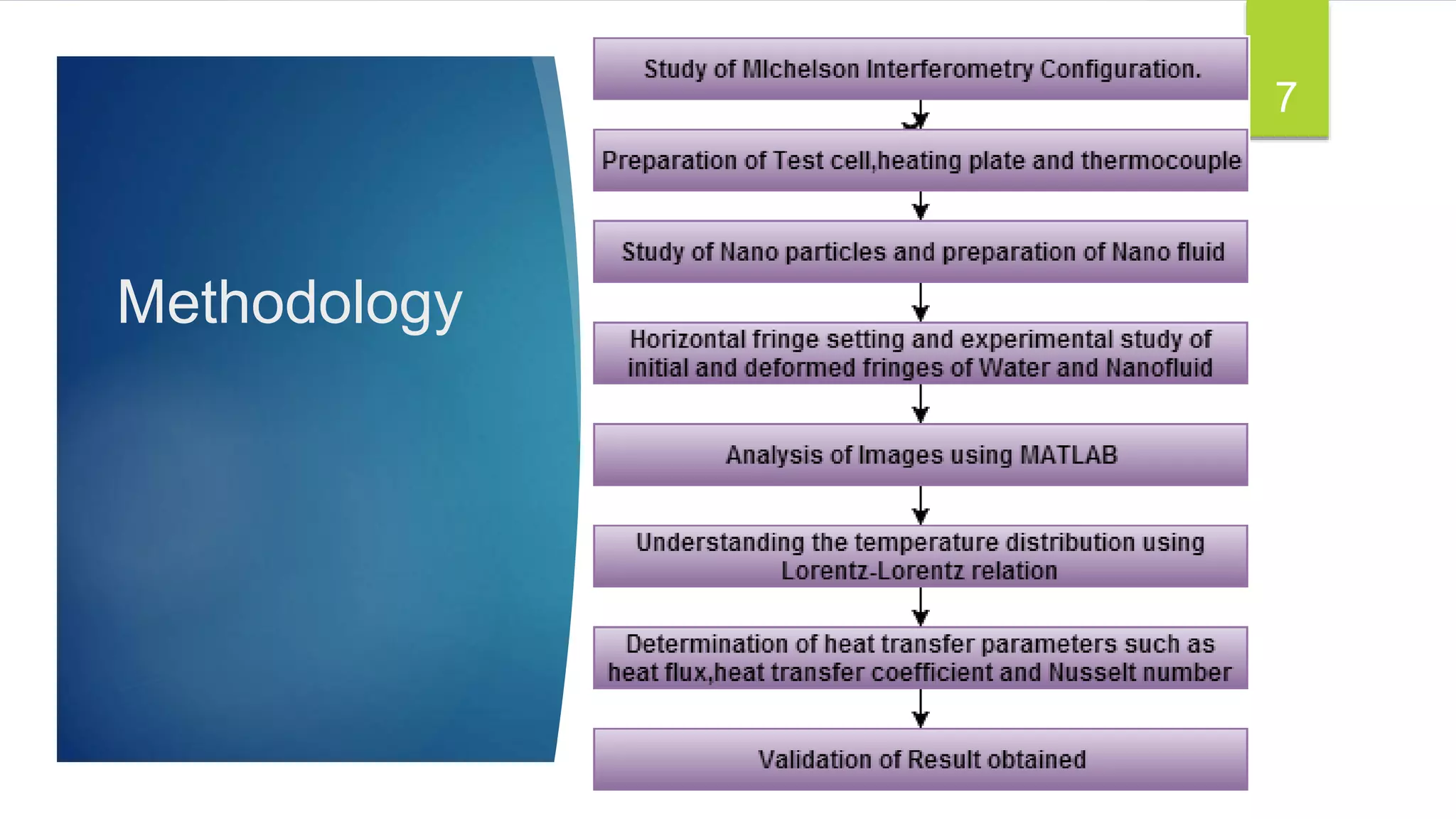
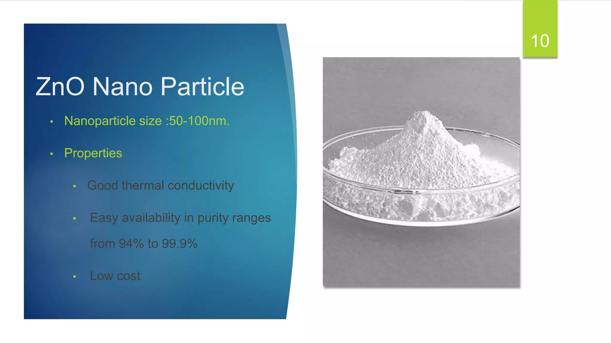
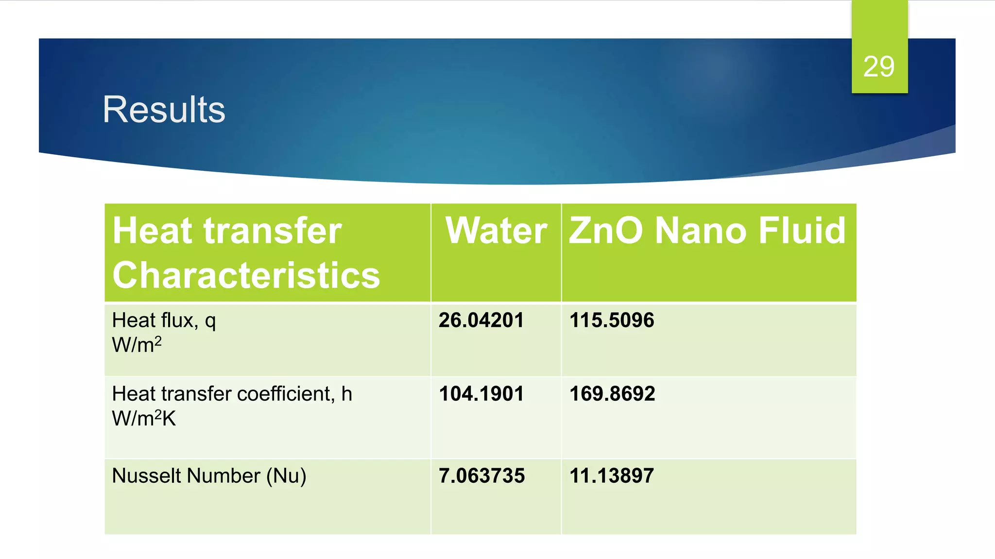
Investigations on Heat Transfer
Properties of Nano Fluid using
Michelson Interferometry
Project guide : Asst. Prof Anooplal B
Mentor : Dr. Binoy Baby
1
Akash R S
Febin Tom
J Amal Dev
Geo Jacob
Contents
 Introduction
 Motivation and Need
 Methodology
 Equipment and Technologies
 Analysis
 Results
 Conclusions
 References
2
Objective
To determine the heat transfer
characteristics of Nano fluid using
Michelson Interferometry without
disturbing the thermal flow field
3
Introduction
 Advances in nanotechnology have led to development of Nano fluids.
 Enhanced thermal characteristics of Nano fluids extends its application to
cooling
 Interferometric technique used to measure physical effects of transparent
media
 Study is made into the heat transfer characteristics of Nano Fluids using
Michelson Interferometry
4
Motivation and Need
Miniaturization of energy efficient heat transfer
equipment in the advanced field of mechatronics,
Biometrics, space technology and information
technology.
Poor Thermal Conductivity of Common Coolants
So a non-intrusive optical imaging technique
necessary is needed to understand the heat transfer
characteristics.
5
Scope of the Project
 Knowledge of the heat transfer characteristics of Nano fluids is
found to be very critical in deciding their suitability for thermal
applications.
 Interferometry is a more accurate method for determination of
different heat transfer parameters
6
Methodology
7
Interferometry
 A family of techniques in which waves, usually
electromagnetic are superimposed in order to extract
information about waves.
 Combination of waves results in some meaningful property
that is diagnostic to the original state of the wave
8
9
ZnO Nano Particle
• Nanoparticle size :50-100nm.
• Properties
• Good thermal conductivity
• Easy availability in purity ranges
from 94% to 99.9%
• Low cost
10
Nano fluids
Base fluids Water
Oil
Ethylene glycol
Refrigerants
Nanoparticles Oxides
Metals
Carbon Nanotubes
Nano fluids are colloidal
suspensions of
nanoparticles in common
fluids
11
Preparation of ZnO Nano Fluid
 Nanoparticles were mixed with water at
0.1% volume
 It was then sonicated using ultrasonic mixer
Sonix VCX 130 (20 kHz, 130 W) with
amplitude of 123 μm for 32 minutes.
 This process was done in order to ensure
uniform mixing of nanoparticles with water.
12
Equipment and Technologies
 Michelson Interferometer
 He Ne Laser
 Test Cell
 Heating Plate
 Thermocouple K type
 Vernier Calliper
 Digital Camera for image
capture
13
MICHELSON INTERFEROMETER
• Consists of a He Ne laser source, a beam splitter, two front-coated plane
mirrors.
14
Equipment and Technologies
Test Cell
 sensitivity 41 µV/°C
 90% nickel, 10% chromium 95% nickel,
2% aluminum, 2% manganese and 1%
silicon.
Thermocouple K type
15
 Dimensions 40*40*50mm
 Material-Glass
Equipment and Technologies
Heating plate
 Made using Nichrome wire of 9m length
and 40gauge
 Insulation provided by Mica coating and
it is covered using stainless steel
 Maximum temperature of 300°C can be
obtained at a power input of 100w and
220V.
16
Study of Experimental Setup
17
18
Fringe Setting
 Air as medium
 Water as medium
 ZnO Nano fluid
19
Fringe setting with water as medium
Initial fringe Deformed fringe
20
Fringe setting with ZnO Nano fluid as
medium
Initial Fringe Deformed Fringe
21
Analysis
Processing
images by
MATLAB
software and
convert data to
matrix format.
Digitally
subtract
deformed
fringe from
initial fringe.
Intensity profile of the
resultant image were
drawn over the
distance between heat
source(vertical plate)
and thermocouple.
From pixel coordinates
and length between
heat source and
thermocouple
determine the length of
one pixel and width of
heat source.
A polynomial was
fitted from the
graph plotted
using densities of
medium at
different
temperature.
With reference to
the Lorentz-
Lorenz relation is
used to find the
temperature at
isotherms.
22
Digitally subtracted
image for water
23
Thermocouple
Digitally subtracted
image for ZnO Nano
fluid
24
Thermocouple
25
Analysis: Water
Intensity profile Temperature profile
26
309.9
310
310.1
310.2
310.3
310.4
310.5
0 0.001 0.002 0.003 0.004 0.005 0.006
TEMPERATURE(K)
DISTANCE (M)
T Poly. (T)
Intensity(cd)
Analysis: ZnO Nano fluid
Intensity profile Temperature distribution
27
309.8
310
310.2
310.4
310.6
310.8
311
311.2
311.4
0 0.001 0.002 0.003 0.004 0.005TEMPERATURE(K)
DISTANCE(M)
T Poly. (T)
Intensity(cd)
Analysis
 From the graph the relationship between temperature and distance is
obtained as
T = -3E+06x3 + 24671x2 + 44.139x + 310
Slope of the graph dT/dx = 44.139K/m
Heat flux, q = k* dT/dx
Heat transfer coefficient, h = (k*dT/dx)/∆T
Nusselt Number, Nu = hl/k
28
Results
Heat transfer
Characteristics
Water ZnO Nano Fluid
Heat flux, q
W/m2
26.04201 115.5096
Heat transfer coefficient, h
W/m2K
104.1901 169.8692
Nusselt Number (Nu) 7.063735 11.13897
29
Results and Discussion
 Heat transfer properties of 0.003% ZnO Nano fluids were
studied.
 When compared to that of water heat transfer properties of
ZnO Nano fluids was found to be more as indicated by
increase in heat flux, heat transfer coefficient and Nusselt
Number.
30
Conclusions
 ZnO based Nano fluids were prepared using two step
method and its heat transfer characteristics were studied.
 Michelson interferometry was used as an intrusive technique
to understand the temperature distribution.
31
References
 Binoy Baby, and C. B. Sobhan, “Investigations on Forced Convection in a Mesochannel
with Irregular Cross Section,” JOURNAL OF THERMOPHYSICS AND HEAT TRANSFER
Vol. 27, No. 1, January–March 2013.
 Anooplal B, Binoy Baby, “Temperature Distribution Measurement by Michelson
Interferometer,” International Journal of Innovative Research in Science, Engineering and
Technology. Vol.4, Special Issue 12, September 2015.
 R. S. Vajjha, D. K. Das, and B. M. Mahagaonkar,” Density Measurement of Different
Nanofluids and Their Comparison With Theory,” Petroleum Science and Technology, 01
April 2009.
32
33
Analysis of fringes obtained for water
Commands
>> J=imread('e:362.jpg');
>> imshow(J)
Warning: Image is too big to fit on screen;
displaying at 67%
> In imuitoolsprivateinitSize at 73
In imshow at 262
>> improfile
Intensity Profile
34
Analysis of fringes obtained for ZnO
Nanofluid
Commands
>> J=imread('e:362.jpg');
>> imshow(J)
Warning: Image is too big to fit on screen;
displaying at 67%
> In imuitoolsprivateinitSize at 73
In imshow at 262
>> improfile
Intensity Profile
35
Calculations
 Find the position of the isotherm.
 Value of 1pixel=(Total distacne)/(maximum pixel number).
 Find the temperature of isotherms using Glodstone relations.
36
37

INVESTIGATION ON HEAT TRANSFER PROPERTIES USING MICHELSON INTERFEROMETRY

  • 1.
    Investigations on HeatTransfer Properties of Nano Fluid using Michelson Interferometry Project guide : Asst. Prof Anooplal B Mentor : Dr. Binoy Baby 1 Akash R S Febin Tom J Amal Dev Geo Jacob
  • 2.
    Contents  Introduction  Motivationand Need  Methodology  Equipment and Technologies  Analysis  Results  Conclusions  References 2
  • 3.
    Objective To determine theheat transfer characteristics of Nano fluid using Michelson Interferometry without disturbing the thermal flow field 3
  • 4.
    Introduction  Advances innanotechnology have led to development of Nano fluids.  Enhanced thermal characteristics of Nano fluids extends its application to cooling  Interferometric technique used to measure physical effects of transparent media  Study is made into the heat transfer characteristics of Nano Fluids using Michelson Interferometry 4
  • 5.
    Motivation and Need Miniaturizationof energy efficient heat transfer equipment in the advanced field of mechatronics, Biometrics, space technology and information technology. Poor Thermal Conductivity of Common Coolants So a non-intrusive optical imaging technique necessary is needed to understand the heat transfer characteristics. 5
  • 6.
    Scope of theProject  Knowledge of the heat transfer characteristics of Nano fluids is found to be very critical in deciding their suitability for thermal applications.  Interferometry is a more accurate method for determination of different heat transfer parameters 6
  • 7.
  • 8.
    Interferometry  A familyof techniques in which waves, usually electromagnetic are superimposed in order to extract information about waves.  Combination of waves results in some meaningful property that is diagnostic to the original state of the wave 8
  • 9.
  • 10.
    ZnO Nano Particle •Nanoparticle size :50-100nm. • Properties • Good thermal conductivity • Easy availability in purity ranges from 94% to 99.9% • Low cost 10
  • 11.
    Nano fluids Base fluidsWater Oil Ethylene glycol Refrigerants Nanoparticles Oxides Metals Carbon Nanotubes Nano fluids are colloidal suspensions of nanoparticles in common fluids 11
  • 12.
    Preparation of ZnONano Fluid  Nanoparticles were mixed with water at 0.1% volume  It was then sonicated using ultrasonic mixer Sonix VCX 130 (20 kHz, 130 W) with amplitude of 123 μm for 32 minutes.  This process was done in order to ensure uniform mixing of nanoparticles with water. 12
  • 13.
    Equipment and Technologies Michelson Interferometer  He Ne Laser  Test Cell  Heating Plate  Thermocouple K type  Vernier Calliper  Digital Camera for image capture 13
  • 14.
    MICHELSON INTERFEROMETER • Consistsof a He Ne laser source, a beam splitter, two front-coated plane mirrors. 14
  • 15.
    Equipment and Technologies TestCell  sensitivity 41 µV/°C  90% nickel, 10% chromium 95% nickel, 2% aluminum, 2% manganese and 1% silicon. Thermocouple K type 15  Dimensions 40*40*50mm  Material-Glass
  • 16.
    Equipment and Technologies Heatingplate  Made using Nichrome wire of 9m length and 40gauge  Insulation provided by Mica coating and it is covered using stainless steel  Maximum temperature of 300°C can be obtained at a power input of 100w and 220V. 16
  • 17.
  • 18.
  • 19.
    Fringe Setting  Airas medium  Water as medium  ZnO Nano fluid 19
  • 20.
    Fringe setting withwater as medium Initial fringe Deformed fringe 20
  • 21.
    Fringe setting withZnO Nano fluid as medium Initial Fringe Deformed Fringe 21
  • 22.
    Analysis Processing images by MATLAB software and convertdata to matrix format. Digitally subtract deformed fringe from initial fringe. Intensity profile of the resultant image were drawn over the distance between heat source(vertical plate) and thermocouple. From pixel coordinates and length between heat source and thermocouple determine the length of one pixel and width of heat source. A polynomial was fitted from the graph plotted using densities of medium at different temperature. With reference to the Lorentz- Lorenz relation is used to find the temperature at isotherms. 22
  • 23.
    Digitally subtracted image forwater 23 Thermocouple
  • 24.
    Digitally subtracted image forZnO Nano fluid 24 Thermocouple
  • 25.
  • 26.
    Analysis: Water Intensity profileTemperature profile 26 309.9 310 310.1 310.2 310.3 310.4 310.5 0 0.001 0.002 0.003 0.004 0.005 0.006 TEMPERATURE(K) DISTANCE (M) T Poly. (T) Intensity(cd)
  • 27.
    Analysis: ZnO Nanofluid Intensity profile Temperature distribution 27 309.8 310 310.2 310.4 310.6 310.8 311 311.2 311.4 0 0.001 0.002 0.003 0.004 0.005TEMPERATURE(K) DISTANCE(M) T Poly. (T) Intensity(cd)
  • 28.
    Analysis  From thegraph the relationship between temperature and distance is obtained as T = -3E+06x3 + 24671x2 + 44.139x + 310 Slope of the graph dT/dx = 44.139K/m Heat flux, q = k* dT/dx Heat transfer coefficient, h = (k*dT/dx)/∆T Nusselt Number, Nu = hl/k 28
  • 29.
    Results Heat transfer Characteristics Water ZnONano Fluid Heat flux, q W/m2 26.04201 115.5096 Heat transfer coefficient, h W/m2K 104.1901 169.8692 Nusselt Number (Nu) 7.063735 11.13897 29
  • 30.
    Results and Discussion Heat transfer properties of 0.003% ZnO Nano fluids were studied.  When compared to that of water heat transfer properties of ZnO Nano fluids was found to be more as indicated by increase in heat flux, heat transfer coefficient and Nusselt Number. 30
  • 31.
    Conclusions  ZnO basedNano fluids were prepared using two step method and its heat transfer characteristics were studied.  Michelson interferometry was used as an intrusive technique to understand the temperature distribution. 31
  • 32.
    References  Binoy Baby,and C. B. Sobhan, “Investigations on Forced Convection in a Mesochannel with Irregular Cross Section,” JOURNAL OF THERMOPHYSICS AND HEAT TRANSFER Vol. 27, No. 1, January–March 2013.  Anooplal B, Binoy Baby, “Temperature Distribution Measurement by Michelson Interferometer,” International Journal of Innovative Research in Science, Engineering and Technology. Vol.4, Special Issue 12, September 2015.  R. S. Vajjha, D. K. Das, and B. M. Mahagaonkar,” Density Measurement of Different Nanofluids and Their Comparison With Theory,” Petroleum Science and Technology, 01 April 2009. 32
  • 33.
  • 34.
    Analysis of fringesobtained for water Commands >> J=imread('e:362.jpg'); >> imshow(J) Warning: Image is too big to fit on screen; displaying at 67% > In imuitoolsprivateinitSize at 73 In imshow at 262 >> improfile Intensity Profile 34
  • 35.
    Analysis of fringesobtained for ZnO Nanofluid Commands >> J=imread('e:362.jpg'); >> imshow(J) Warning: Image is too big to fit on screen; displaying at 67% > In imuitoolsprivateinitSize at 73 In imshow at 262 >> improfile Intensity Profile 35
  • 36.
    Calculations  Find theposition of the isotherm.  Value of 1pixel=(Total distacne)/(maximum pixel number).  Find the temperature of isotherms using Glodstone relations. 36
  • 37.

Editor's Notes