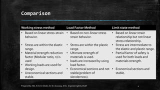
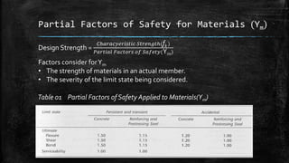
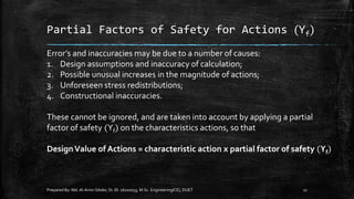
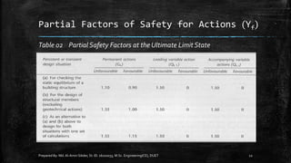
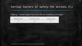
General, Basic Methods of Design, Comparison Between Design Methods, Limit State Design, Types of Limit State Design, Ultimate Limit State (ULS), Serviceability Limit State (SLS), Characteristic Materials Strength, Characteristic Actions, Partial Factors of Safety for Materials and Actions, Combinations of Actions, Design Values of Actions at the ULS and SLS.
1. Introduction to
Limit State Design
Prepared By: Md.Al-Amin Sikder, St. ID. 16102033, M.Sc. Engineering(CE), DUET 1
Prepared By
Md. Al-Amin Sikder
St. ID. 16201044, M.Sc. Engg.
Submitted To
Dr. Md. Rezaul Karim
Professor
Department of Civil Engineering
Dhaka University of Engineering & Technology, Gazipur-1700,
Bangladesh.
2. General
Limit State Design of an engineering structure must ensure that
▪ Under the worst loadings the structure is safe, and
▪ During normal working conditions the deformation of the members
does not detract from the appearance, durability or performance of
the structure.
Prepared By: Md.Al-Amin Sikder, St. ID. 16102033, M.Sc. Engineering(CE), DUET 2
3. Basic Methods of Design
1. Permissible Stress Method ( orWorking Stress Method)
2. Load Factor Method ( or Ultimate Strength Method)
3. Limit State Method
Prepared By: Md.Al-Amin Sikder, St. ID. 16102033, M.Sc. Engineering(CE), DUET 3
4. Comparison
Prepared By: Md.Al-Amin Sikder, St. ID. 16102033, M.Sc. Engineering(CE), DUET 4
Working stress method Load Factor Method Limit state method
• Based on linear stress-strain
behavior.
• Stress are within the elastic
range.
• Material strength reduction
factor (Modular ratio, n) is
used
• Working loads are used for
design.
• Uneconomical sections and
stable.
• Based on non-linear stress
strain behavior.
• Stress are within the plastic
range.
• Ultimate strength of
materials is used.
• loads are increased by using
load factor.
• Economical sections and not
stable(problem of
slenderness).
• Based on linear strain
relationship but not linear
stress relationship.
• Stress are intermediate to
the elastic and plastic range.
• Partial factor of safety is
used for both loads and
materials strength.
• Economical sections and
stable.
5. Limit States (LS)
The purpose of design is to achieve acceptable probabilities that a structure will
not become unfit for its intended use during the expected life of the structure.
Two principal types of Limit State
1. Ultimate Limit State (ULS)
2. Serviceability Limit States (SLS)
Prepared By: Md.Al-Amin Sikder, St. ID. 16102033, M.Sc. Engineering(CE), DUET 5
6. Limit State Con’t
Prepared By: Md.Al-Amin Sikder, St. ID. 16102033, M.Sc. Engineering(CE), DUET 6
Limit State of Strength Serviceability Limit State
• Strength (yield, buckling)
• Stability against overturning and sway
• Fracture due to fatigue
• Brittle Fracture
• Deflection
• Cracking
• Durability
• Excessive vibration
• Fatigue
• Fire resistance
• Special circumstance (Earthquake and
corrosion resistance etc.)
7. Limit State Con’t
Characteristic Materials Strength
The strengths of materials upon which
a design is based are, normally, those
strengths bellow which results are
unlikely to fall.These are called
‘Characteristic’ Strengths.
fk = fm- 1.64s
Where, fk = Characteristic Strength,
fm = mean strength,
s = standard deviation
Prepared By: Md.Al-Amin Sikder, St. ID. 16102033, M.Sc. Engineering(CE), DUET 7
Figure 01: Normal Frequency Distribution of Strengths
8. Limit State Con’t
Prepared By: Md.Al-Amin Sikder, St. ID. 16102033, M.Sc. Engineering(CE), DUET 8
Characteristic Actions
In Eurocode terminology the sets of applied forces (or loads)
for which a structure is to be designed are called ‘actions’.
Characteristic Action = Mean Action ± 1.64 Standard Deviation
9. Partial Factors of Safety
Prepared By: Md.Al-Amin Sikder, St. ID. 16102033, M.Sc. Engineering(CE), DUET 9
Other possible variations such as constructional tolerances are allowed
for by the partial factors of safety applied to the strength of materials
and to the actions.
In practice, the values adopted are based on experience and simplified
calculations.
Two categories
1. Partial Factors of Safety for materials (Υm)
2. Partial Factors of Safety for actions (Υf)
10. Partial Factors of Safety for Materials (Υm)
Prepared By: Md.Al-Amin Sikder, St. ID. 16102033, M.Sc. Engineering(CE), DUET 10
Design Strength =
𝐶ℎ𝑎𝑟𝑎𝑐𝑦𝑒𝑟𝑖𝑠𝑡𝑖𝑐 𝑆𝑡𝑟𝑒𝑛𝑔𝑡ℎ(fk )
𝑃𝑎𝑟𝑡𝑖𝑎𝑙 𝐹𝑎𝑐𝑡𝑜𝑟𝑠 𝑜𝑓 𝑆𝑎𝑓𝑒𝑡𝑦(Υm)
Factors consider forΥm
• The strength of materials in an actual member.
• The severity of the limit state being considered.
Table 01 Partial Factors of Safety Applied to Materials(Υm)
11. Partial Factors of Safety for Actions (Υf)
Prepared By: Md.Al-Amin Sikder, St. ID. 16102033, M.Sc. Engineering(CE), DUET 11
Error’s and inaccuracies may be due to a number of causes:
1. Design assumptions and inaccuracy of calculation;
2. Possible unusual increases in the magnitude of actions;
3. Unforeseen stress redistributions;
4. Constructional inaccuracies.
These cannot be ignored, and are taken into account by applying a partial
factor of safety (Υf) on the characteristics actions, so that
DesignValue of Actions = characteristic action x partial factor of safety (Υf)
12. Partial Factors of Safety for Actions (Υf)
Prepared By: Md.Al-Amin Sikder, St. ID. 16102033, M.Sc. Engineering(CE), DUET 12
Table 02 Partial Safety Factors at the Ultimate Limit State
13. Partial Factors of Safety for Actions (Υf)
Prepared By: Md.Al-Amin Sikder, St. ID. 16102033, M.Sc. Engineering(CE), DUET 13
Table 03 Partial Safety Factors at the Serviceability Limit State
14. Combination of Actions
Prepared By: Md.Al-Amin Sikder, St. ID. 16102033, M.Sc. Engineering(CE), DUET 14
1. CombinationValues ofVariable Actions (ψ0);
2. FrequentValues ofVariable Actions (ψ1);
3. Quasi-permanentValues ofVariable Actions (ψ2).
Table 04 Values of ψ for different load combinations
15. Combination of Actions con’t
Prepared By: Md.Al-Amin Sikder, St. ID. 16102033, M.Sc. Engineering(CE), DUET 15
Figure 02 Wind and imposed load acting on an
office building – stability check
16. Design Values of Actions at the ULS
Prepared By: Md.Al-Amin Sikder, St. ID. 16102033, M.Sc. Engineering(CE), DUET 16
DesignValue (Ed) = (Factors Permanent Actions) + (Factored Single Leading
Variable Action) + (Factored remaining accompanying
Variable Actions)
Note that, ‘+’ sign means ‘combined with’ not algebraic.
17. Prepared By: Md.Al-Amin Sikder, St. ID. 16102033, M.Sc. Engineering(CE), DUET 17
Design Values of Actions at the ULS con’t
Table 04 Combination actions and load factors at the ULS
18. Prepared By: Md.Al-Amin Sikder, St. ID. 16102033, M.Sc. Engineering(CE), DUET 18
Design Values of Actions at the SLS
1. CombinationValues ofVariable Actions (ψ0);
2. FrequentValues ofVariable Actions (ψ1);
3. Quasi-permanentValues ofVariable Actions (ψ2).
Note that, ‘+’ sign means ‘combined with’ not algebraic.