“Being proficient withCAD and its user interface can help
make drafting tasks easier based on how familiar you are with
all the tools that are just a click away.”
6.
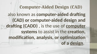
Computer-Aided Design (CAD)
alsoknown as computer-aided drafting
(CAD) or computer-aided design and
drafting (CADD) , is the use of computer
systems to assist in the creation,
modification, analysis, or optimization
of a design.
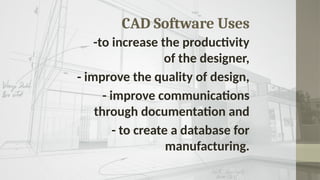
CAD Software Uses
-toincrease the productivity
of the designer,
- improve the quality of design,
- improve communications
through documentation and
- to create a database for
manufacturing.
9.
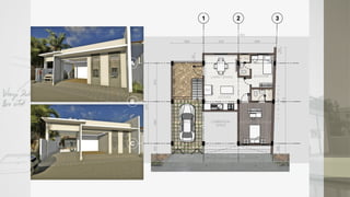
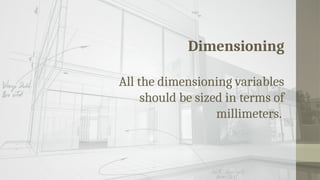
CAD Outputs
The outputof CAD must convey
information, such as :
-materials,
-processes,
-dimensions,
-and tolerances,
according to application-specific
conventions.
The Interface
The AutoCADuser interface — or UI as it’s
often referred to
ELEMENTS
Title Bar Command Line
Menus Status Bar
Toolbar Status bar Tray
Info Center Clean Screen icon
Dockable Window
“Being proficient withCAD and its user interface can help
make drafting tasks easier based on how familiar you are with
all the tools that are just a click away.”
15.
Setting Up AutoCADto Work With
Architectural Drafting Style
Creating a Template File
Creating a User Profile
16.
Creating a TemplateFile
layers
text styles
dimension styles
layouts and
plotting
Your Template file can then be used to open new drawings to
eliminate having to set up these changes again in the future.
17.
Creating a TemplateFile
layers
text styles
dimension styles
layouts and
plotting
Your Template file can then be used to open new drawings to
eliminate having to set up these changes again in the future.
18.
Templates have thefilename extension
of *.dwt. The easiest way to make your
standard settings permanent for later
reuse is to create your own Template
File.
19.
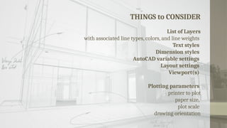
THINGS to CONSIDER
Listof Layers
with associated line types, colors, and line weights
Text styles
Dimension styles
AutoCAD variable settings
Layout settings
Viewport(s)
Plotting parameters
printer to plot
paper size,
plot scale
drawing orientation
20.
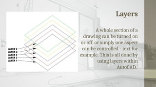
Layers
A whole sectionof a
drawing can be turned on
or off, or simply one aspect
can be controlled - text for
example. This is all done by
using layers within
AutoCAD.
21.
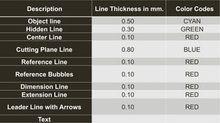
Description Line Thicknessin mm. Color Codes
Object line 0.50 CYAN
Hidden Line 0.30 GREEN
Center Line 0.10 RED
Cutting Plane Line 0.80 BLUE
Reference Line 0.10 RED
Reference Bubbles 0.10 RED
Dimension Line 0.10 RED
Extension Line 0.10 RED
Leader Line with Arrows 0.10 RED
Text
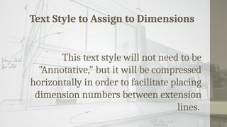
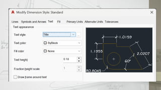
Text Style toAssign to Dimensions
This text style will not need to be
"Annotative," but it will be compressed
horizontally in order to facilitate placing
dimension numbers between extension
lines.
26.
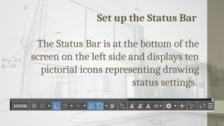
Set up theStatus Bar
The Status Bar is at the bottom of the
screen on the left side and displays ten
pictorial icons representing drawing
status settings.
27.
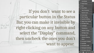
If you don’twant to see a
particular button in the Status
Bar, you can make it invisible by
right clicking on any button and
select the "Display" command,
then uncheck the ones you don't
want to appear.
28.
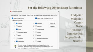
Set the followingObject Snap functions
Endpoint
Midpoint
Center
Node
Quadrant
Intersection
Perpendicular
Nearest
29.
Set the followingObject Snap functions
Endpoint
Midpoint
Center
Node
Quadrant
Intersection
Perpendicular
Nearest
30.
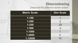
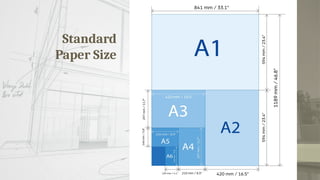
Standard Printing Specifications
Giventhis ease of changing sizes, it is
of course common to copy or print a
given document on different sizes of
paper.
31.
Standard Printing Specifications
Giventhis ease of changing sizes, it is of
course common to copy or print a given
document on different sizes of paper.
Create a Layoutof
Border and Title Block
Elements of the Layout of Border
and Title Blocks
A unique name
Title informational border
Paper Space and Model Space
Viewpoints


![DepEd-MATATAG PPT limit festival [Autosaved] [Autosaved].pptx](https://cdn.slidesharecdn.com/ss_thumbnails/deped-matatagpptlimitfestivalautosavedautosaved-250710135729-7ac77bb5-thumbnail.jpg?width=640&height=640&fit=bounds)


