Download to read offline

![Gravity Gradient is the difference in centripetal acceleration that a person would
experience between their head and their feet, due to their location at different radii.
The basic equation: gradient = [w2Rf – w2(Rf-1m)]/ (w2Rf)
Solves as: gradient = 1m / Rf
Or: Rf_min = 1m / gradient
(where “w” is angular velocity in radians/sec; Rf is the radial distance from the
habitat’s rotational axis to the floor surface, in meters)
With this in mind, an 8% gradient yields an Rf_min = 12.5m; a 25% gradient yields an
Rf_min = 4.0m. Cramer’s 3% G delta yields a 33.3m minimum floor radius for 1G
nominal habitats, For a 30% G nominal habitat, Cramer’s 3% G delta represents a
10% gradient, and therefore a 10.0m minimum floor radius.
The Maximum Angular Velocity of the habitat bears directly upon the likelihood of
inducing motion sickness in the occupants. This motion sickness is related to
gyroscopic coupling of normal head rotations of the occupants within the rotating
frame of reference of the centripetal habitat, as it affects the vestibular fluid within
their inner ears (Graybiel, 1975). Graybiel states that, “at 1.0 rpm even highly
susceptible subjects were [relatively] symptom-free. At 3.0 rpm subjects experienced
symptoms, but were not significantly handicapped. At 5.4 rpm, only subjects with
low susceptibility performed well and by the second day were almost free from
symptoms.” A two-day acclimation period for subjects with “low susceptibility”
would appear to place 5.4 rpm as an upper limit, with 3.0 rpm as a reasonable value.
Since Earth-based centrifuge testing naturally imposes a 1G reference, it cannot be
known if this reference adds an offset (physical or perceptual) to the test subject’s
sensitivity to the rotational cross-coupling effects. In addition, these tests dealt
primarily with acclimation, and not long-term health effects.
A maximum angular velocity of 3 rpm is therefore selected.
In general, the “comfortable” gravity range falls within 30% to 100% of Earth-normal
gravity. Hill & Schnitzer’s value of 3.5% G has been classified as more of a
mathematical limit than a true physical requirement (Hall, 1997). What none of the
previous estimates were able to determine, however, was the minimum value
acceptable for long-term health of the inhabitants (Czarnik, 1999). In the absence of
these additional data, and in light of the known value of a 1G environment, a value of
100% Earth-normal gravity is proposed.
The expression for centripetal acceleration is straightforward:
Acent = Rf* w2
Solving for Rf: Rf = Acent/w2
Using the previously selected values, a floor radius of 99.41m is achieved.
3](https://image.slidesharecdn.com/intra-3-120807204505-phpapp01/85/Intra-3-3-320.jpg)
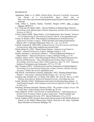

This document proposes a solution for transferring personnel and supplies between a large, rotating habitat wheel that provides artificial gravity and a central, non-rotating utility core in an orbital space station. The solution involves a dedicated subway system with cars that travel on tracks between the rotating wheel, moving at 31.3 m/s, and the stationary core. The subway cars would slow or speed up using linear induction motors to match speeds, providing a safe way to cross the speed differential while keeping the rotation of the main habitat and stationary core unchanged.


