SlideShare a Scribd company logo
1 of 179
Download to read offline
What is a Network?
• In its simplest form, a network is nothing more than “two connected
computers sharing resources with one another.”
• It is composed of two main aspects:
o Physical Connection (wires, cables, wireless media)
o Logical Connection (data transporting across the physical media)
Some Basic Networking Rules
• The computers in a network must use the same procedures for sending and
receiving data. We call these communication protocols.
• Data must be delivered uncorrupted. If it is corrupted, it’s useless. (There are
Exceptions)
• Computers in a network must be capable of determining the origin and
destination of a piece of information, i.e., its IP and Mac Address.
Types of Computer Networks (by Size)
• Personal Area Network (PAN)
• Local Area Network (LAN)
• Wireless Local Area Network (WLAN)
• Campus Area Network (CAN)
• Metropolitan Area Network (MAN)
• Wide Area Network (WAN)
Network Architecture
Client-Server
Peer-to-Peer
• All computers on the network are
peers
• No dedicated servers
• There’s no centralized control over
shared resources
• Any device can share its resources as
it pleases
• All computers can act as either a
client or a server
• Easy to set-up, and common in homes
and small businesses
• The network is composed of client and
servers
• Servers provide resources
• Clients receive resources
• Servers provide centralized control over
network resources (files, printers, etc.)
• Centralizes user accounts, security, and
access controls to simplify network
administration
• More difficult to setup and requires an IT
administrator
Why Build a Computer Network?
• Before computer networks, people sent and received information by hand,
using the postal service. This is slow and can be unreliable.
• Computer networks enable faster, more efficient modes of communication,
i.e., email, video conferencing, etc.
• Computer networks and the sharing of electronic data encourage the use of
standard policies and procedures.
• Computer networks provide backup and recovery support for our data, i.e.,
redundancy.
• Computer networks lead to cost savings.
Personal Area Network (PAN)
• Ultra-small networks used for personal use to share
data from one device to another.
• Can be wired (PAN) or wireless (WPAN):
o USB
o Bluetooth
o NFC
o ANT+
• Examples:
o Smart Phone to Laptop
o Smart Watch to Smart Phone
o Smart Phone Hands-Free Car Calling
o Heart Rate Monitor to Smart Phone
Local Area Network (LAN)
• A computer network within a small geographical
area, such as a single room, building or group of
buildings.
• Considered to be self-contained:
o All devices are directly connected via cables and/or
short-range wireless technology.
o Doesn’t require a leased telecommunications line
from an Internet Service Provider (ISP).
• Examples:
o Home Network
o Small Business or Office Network
Wireless Local Area Network (WLAN)
• A LAN that’s dependent on wireless connectivity
or one that extends a traditional wired LAN to a
wireless LAN.
• Most home networks are WLANs.
Campus Area Network (CAN)
• A computer network of multiple
interconnected LANs in a limited geographical
area, such as a corporate business park,
government agency, or university campus.
• Typically owned or used by a single entity.
Metropolitan Area Network (MAN)
• A computer network that interconnects
users with computer resources in a city.
• Larger than a campus area network, but
smaller than a wide area network.
Wide Area Network (WAN)
• A computer network that extends over a
large geographical distance, typically
multiple cities and countries.
• WANs connect geographically distant LANs.
• Typically use leased telecommunications
lines from ISPs.
• Examples:
o The Internet
o Corporate Offices in Different States
Some Basic Networking Rules
• The computers in a network must use the same procedures for sending and
receiving data. We call these communication protocols.
• Data must be delivered uncorrupted. If it is corrupted, it’s useless. (There are
Exceptions)
• Computers in a network must be capable of determining the origin and
destination of a piece of information, i.e., its IP and Mac Address.
What is a Network?
• In its simplest form, a network is nothing more than “two connected
computers sharing resources with one another.”
• It is composed of two main aspects:
o Physical Connection (wires, cables, wireless media)
o Logical Connection (data transporting across the physical media)
Computer Networking Protocols
• Computers communicate with each other with network protocols.
• Protocols are rules governing how machines exchange data and
enable effective communication.
• Some Everyday Examples
• When you call somebody, you pick up the phone, ensure there is a dial
tone, and if there is, you dial the number.
• When you drive your car, you obey the rules of the road.
Protocols Continued
• Physical Protocols: describe the medium (wiring), the connections
(RJ-45 port), and the signal (voltage level on a wire).
• Logical Protocols: software controlling how and when data is sent
and received to computers, supporting physical protocols.
• Computer networks depend on many different types of protocols in
order to work properly.
• Example Common TCP/IP Suite of Protocols:
o Web Communication: HTTP
o E-mail: POP3, SMTP, IMAP
o File Transfers: FTP
The OSI Model
What is it?
The Open Systems Interconnection (OSI) Reference Model
• A conceptual framework showing us how data moves
throughout a network.
• Developed by the International Organization for Standardization
(ISO) in 1977.
It’s Purpose
• Gives us a guide to understanding how networks operate.
It’s only a reference model, so don’t get wrapped up in the details.
• Wasn’t implemented in the real world, TCP/IP is.
The OSI Model Stack
The OSI Model breaks down the complex task of computer-to-computer
network communications into seven layers.
Upper Layers (Host Layers)
• Handled by the host computer and performs application-specific functions,
such as data formatting, encryption, and connection management.
Lower Layers (Media Layers)
• Provide network-specific functions, such as routing, addressing, and flow
control.
The OSI Model Visualized
OSI Communication
The TCP/IP Model
• The TCP/IP suite is the most commonly used
protocol suite in the networking world.
• It’s essentially the protocol suite in which
the Internet was built.
• It’s the standard for computer networking.
• It is based on a 4-layer model that is similar
to the OSI model.
• History of TCP/IP:
o Developed by the United States Department
of Defense (DoD) in the early 1970s.
o In 1982, the DOD declared TCP/IP as the
standard for all military computer networking.
o In 1984, broad adoption of TCP/IP began (IBM,
AT&T, etc.).
TCP/IP & OSI Models Side-by-Side
MAC Addresses
Media Access Control (MAC)
• Physical address of the network adapter card
• OSI Layer 2 (Data Link) Layer Address
• TCP/IP Layer 1 (Network Interface) Layer Address
Six bytes (48 bits), Usually Represented Hexadecimal
• First three bytes (24 bits) are assigned by the IEEE to the manufacturer
o Organizationally Unique Identifier (OUI) assigned by IEEE (ex: Dell or
HP)
• Last three bytes (24 bits) are usually assigned sequentially:
o Unique Numbers
00:21:70:6f:06:f2 00-21-70-6F-06-F2
224 = ~16.7 Million Unique Addresses
IP Addresses
• An IP Address is a logical address used in order to uniquely identify
a device on an IP network.
• It’s a Network Layer address associated with routing.
o OSI Layer 3: Network Layer
o TCP/IP Layer 2: Internet Layer
• There are two versions:
o IP version 4 (IPv4)
▪ Example: 192.168.0.1
o IP version 6 (IPv6)
▪ Example: 2001:DB8:85A3:0:0:8A2E:370:7334
• We’ll be discussing both versions in this course.
Comparing IP and MAC Addresses
MAC Addresses
IP Addresses
• Network (OSI Layer 3) Addresses
• Logical Addresses
• Assigned in Operating System
• Allows network-to-network
communication via routers
• WAN communication
• Data Link (OSI Layer 2) Addresses
• Physical Addresses
• Physically burned on NIC
• Allows internetwork communication via
hubs, switches, and routers
• Local LAN communication
Half vs. Full Duplex Communication
• Network communication will occur in either full or half duplex mode:
o Half Duplex: Can send and receive data, but not at the same time.
o Full Duplex: Can send and receive data simultaneously.
Network Transmission Types
• Unicast
• Multicast
• Broadcast
Unicast (One-to-One)
Multicast (One-to-Many)
Broadcast (One-to-All)
Introduction to Ethernet
• The most popular networking technology in the world!
• Refers to a family of standards that define the physical and logical
aspects of the world's most popular type of LAN.
• The standard communications protocol for building a local area
network (LAN).
• Physical
o Cabling, Connectors, Equipment, etc.
• Logical
o Network Access Method, i.e., Carrier Sense Multiple Access (CSMA)
Physical vs. Logical Topologies
Physical topologies describe the placement of network devices and
how they are physically connected.
Logical topologies describe how data flows throughout a network.
Wired Network Topologies
• Four Specific Topologies:
o Bus
o Ring
o Star
o Mesh
Bus Topology
• All devices are connected to a single coaxial network cable.
o Devices are connected via a vampire tap or T-Connector.
o Terminators are required at both ends of the cable to prevent signal bounce.
o Antiquated technology.
• Only one end device can be active on the network at a time.
o Data signals travel in both directions and are received by all devices on the network.
• A single break in the cable can take down the entire network.
Ring Topology
• All devices are connected in a circular fashion.
• Each computer is connected to two other
computers.
• Data travels from node-to-node with each
computer handling data, either unidirectional
or bidirectional.
• Each device (node) in the ring regenerates the
signal, acting as a repeater.
• Failure of a single node can take down the
entire network.
• Fiber Distributed Data Interface (FDDI) uses
two counter-rotating ring topologies for
redundancy.
Star Topology
• All devices are connected to a central
connecting device, which is usually a switch.
• Devices send data to the switch, which
forwards it to the appropriate destination
device.
• Popular topology in today’s networks.
• Used in most large and small networks.
• Central device is a single point of failure.
Mesh Topology
• Each device is connected to every other
device by separate cabling.
• Highly redundant and fault-tolerance.
• Expensive to install.
• Commonly used in Enterprise Networks &
WANs.
• Two Types:
o Partial Mesh
o Full Mesh
Wireless Network Topologies
• Wireless networks utilize radio frequencies (RF) to communicate.
• Three Specific Topologies:
o Ad hoc
o Infrastructure
o Mesh
Ad hoc
• Peer-to-peer (P2P) wireless
network where no wireless
access point (WAP)
infrastructure exits.
• The devices communicate
directly with one another.
• Personal area networks
(PANs) are a common
example of Ad hoc wireless
networks.
Infrastructure
• Wireless network that uses a
wireless access point (WAP)
as its central connecting
device.
• Infrastructure wireless
networks (WLANs) are
commonly used in homes and
small offices.
Mesh
• Just like a wired mesh design,
wireless mesh networks utilize
several wireless access points
(nodes) to create a robust
wireless network that is:
o Scalable
o Self-Healing
o Reliable (redundancy)
• Common in larger homes and
businesses.
Network Interface Card (NIC)
• The network adapter installed on
your network device.
• Provides the physical and
electrical, light or radio frequency
connections to the network
media.
• It can either be an expansion card,
USB devices or built directly into
the motherboard.
Hubs
• Used to Connect Devices Together Within a Network
• Used in Early Networks; Replaced by Switches
• “Multi-Port Repeater”
o Traffic goes in one port and is repeated (broadcasted)
out every other port
o OSI Layer 1 Device
o Dumb Network Device
o Causes increased network collision errors
• Much Less Efficient than a Switch
• Legacy Equipment No Longer Used
Switches
• Connects Devices Together Just Like a Hub
• Intelligent Network Device (OSI Layer 2)
• Memorizes the MAC Address of Each Device Connected to
It via a MAC Address Table, sometimes called a Content
Addressable Memory (CAM) Table
• Pays attention to Source and Destination MAC addresses
during Communication Process
• Use Application-Specific Integrated Circuitry (ASIC), which
makes them Extremely Fast
• Breaks up Collision Domains
o Traffic Goes in One Port and Is Repeated out to Only
Destination Port
o Designed for High Bandwidth
o Standard in Today’s Network Infrastructure
Wireless Access Point (WAP)
• A wireless access point (WAP) is a bridge that extends the wired network to the
wireless network.
• Just like a switch, it’s a Data Link Layer 2 device.
• Note: A WAP is not a router.
Wireless Ranger Extender
• Extends the range of a wireless network by acting as a wireless repeater.
• Rebroadcasts radio frequencies from the wireless network it is associated with
Routers
• Used to Connect Different
Networks Together
• Routes Traffic Between Networks
using IP Addresses
• Uses Intelligent Decisions
(Routing Protocols) to Find the
Best Way to Get a Packet of
Information from One Network to
Another.
• Break Up Broadcast Domains
• OSI Layer 3 Device
o Layer 3 = Router
o Layer 2 = Switch
o Layer 1 = Hub
Modems (Modulators/Demodulators)
• Modems modulate one signal to another, such as analog to digital.
• For example, modulating a telephone analog signal into a digital signal that a router
can understand.
Small Office Home Office (SOHO) Device
• All-In-One Wireless Router with Expanded Capabilities:
o Router, Wireless Access Point, Firewall, Switch, DHCP Server, NAT Device, File Server, etc.
Media Converters
• Like its name implies, it converts one media type to another.
• Layer 1 Device: Performs physical layer signal conversion.
• Ethernet to fiber optic media converters are commonly used.
Firewalls
• Firewalls are the foundation of a defense-in-depth network security strategy.
• They protect your network from malicious activity on the Internet.
• Prevent unwanted network traffic on different networks from accessing your network.
• Firewalls do this by filtering data packets that go through them.
• They can be a standalone network device or software on a computer system, meaning
network-based (hardware) or host-based (software).
Types of Firewalls
Packet Filtering Firewalls
• 1st Generation & Most Basic
• Basic Filtering Rules
Circuit-Level Firewalls
• 2nd Generation
• Monitors Valid/Invalid TCP Sessions
Application Layer 7 (NGFW) Firewalls
• 3rd Generation
• Much more Advanced; Covered Later in Course
DHCP Server
• Dynamic Host Configuration Protocol (DHCP) Server
• Automatically Assigns IP Addresses to Hosts
• Makes Administering a Network Much Easier
• An Alternative is Static IP addressing
• We'll Talk More About DHCP Later in the Course
Voice over IP (VoIP) Endpoints
• Most phone systems run over IP networks via dedicated protocols, such as the Session
Initiation Protocol (SIP), both in-home and office environments.
• VoIP endpoint devices are hardware devices (phones) or software, such as Cisco
Jabber, that allow you to make phone calls.
Types of Network Cabling
• Coaxial
• Twisted Pair
• Fiber Optic
Ethernet Explained
• Ethernet is a network protocol that controls how data is transmitted over a LAN.
• It’s referred to as the Institute of Electrical and Electronics Engineers (IEEE) 802.3
Standard.
• It supports networks built with coaxial, twisted-pair, and fiber-optic cabling.
• The original Ethernet standard supported 10Mbps speeds, but the latest supports
much faster gigabit speeds.
• Ethernet uses CSMA/CD & CSMA/CA access methodology.
Ethernet N<Signaling>-X Naming
• Ethernet uses an “xx Base T” naming convention: 10Base-T
o N: Signaling Rate, i.e., Speed of the cable.
o <Signaling>: Signaling Type: Baseband (Base) communication.
o X: Type of cable (twisted pair or fiber).
Twisted Pair Standards
Cat Network Type Ethernet Standard Speed Max. Distance
Cat 3 Ethernet 10Base-T 10Mbps 100 meters
Cat 5 Fast Ethernet 100Base-TX 100Mbps 100 meters
Cat 5e Gigabit Ethernet 1000Base-T 1Gbps 100 meters
Cat 6
Gigabit Ethernet
10 Gigabit Ethernet
1000Base-T
10GBase-T
1Gbps
10Gbps
100 meters
55 meters
Cat 6a 10 Gigabit Ethernet 10GBase-T 10Gbps 100 meters
Cat 7 10 Gigabit Ethernet 10GBase-T 10Gbps 100 meters
Cat: Copper Cabling Standard.
Coaxial Cable
• Antiquated technology used in the 1980s. Coaxial cables are rarely used today, except
for cable modem connections.
• Categorized as Radio Grade (RG)
o RG-6: Used for modern cable TV and broadband cable modems.
o RG-8: Used in early 10Base5 “Thick-net” Ethernet networks.
o RG-58: Used in early 10Base2 “Thin-net” Ethernet networks.
o RG-59: Used for closed-circuit TV (CCTV) networks
• Metallic shield helps protect against electromagnetic interference (EMI)
Coaxial Cable Connectors
F-Connector
• Screw-on connection
• RG-6 Cable TV and Broadband
Cable Applications.
BNC Connector
• Tension spring twist-on
connection
• RG-8 “Thick-net” and RG-58 “Thin-
net” network applications.
Twisted Pair Copper Cabling
• 4 Twisted Pairs of Wires with RJ-45 Connector
• Balanced pair operation
o + & - Signals
o Equal & Opposite Signal
• Why are they twisted?
o To Help Reduce Interference
• Crosstalk
• Noise (Electromagnetic Interference)
• Security concerns
o Signal Emanations
• 100 Meters Maximum Distance
o Signal Attenuation
Shielded vs. Unshielded & EMI
• Unshielded Twisted Pair (UTP)
o More susceptible to electromagnetic
interference (EMI).
• Shielded Twisted Pair (STP)
o Less susceptible to EMI & Crosstalk (if each
pair shielded).
• Electromagnetic Interference
o The disruption of an electronic device's
operation when it's in the vicinity of an
electromagnetic field caused by another
electronic device (manufacturing equipment,
microwave ovens, etc.).
Roles of Twists
• Increased twists per inch:
o Reduces Crosstalk
o Increases Signals
o Supports Faster Speeds
Twisted Pair Standards
Cat: Copper Cabling Standard.
Cat Network Type Ethernet Standard Speed Max. Distance Frequency
Cat 3 Ethernet 10Base-T 10Mbps 100 meters 16 MHz
Cat 5 Fast Ethernet 100Base-TX 100Mbps 100 meters 100 MHz
Cat 5e Gigabit Ethernet 1000Base-T 1Gbps 100 meters 100 MHz
Cat 6
Gigabit Ethernet
10 Gigabit Ethernet
1000Base-T
10GBase-T
1Gbps
10Gbps
100 meters
55 meters
250 MHz
Cat 6a 10 Gigabit Ethernet 10GBase-T 10Gbps 100 meters 500 MHz
Cat 7 10 Gigabit Ethernet 10GBase-T 10Gbps 100 meters 600 MHz
Other Copper Cable Connectors
DB-25
• 25-pin connection previously commonly
used for serial printer connections.
DB-9
• 9-pin connection used for serial
connections on networking devices
RJ-11
• 4-pin connection used for
telephone connections.
TIA/EIA 568A & 568B Wiring Standards
• Industry-standard that specifies the pin
arrangement for RJ-45 connectors.
• Two Standards:
• 568A & 568B
• 568B is newer and the recommended standard.
• Either can be used.
• Why are standards important?
o Lower Costs
o Increase Interoperability
o Easier Maintenance
Straight-Through & Crossover Cables
Crossover Cable
• Connecting “Like” Devices
o Router to Router
o Computer to Computer
Straight-Through Cable
• Connecting “Unlike” Devices
o Computer to Switch
o Switch to Router
Which Twisted Pairs Are Used?
Gigabit & 10 Gigabit Ethernet
Cat 5e & Faster
All Four Pairs Used:
• Supports bi-directional data transmission on
each pair of wires.
Ethernet & Fast Ethernet
Cat 3 and Cat 5
Only Green and Orange Pairs Used:
• Pins 1, 2, 3, and 6
o One Pair to Transmit Data (TX)
o One Pair to Receive Data (RX)
The Plenum
• The plenum is the open space above the ceiling or below a raised floor.
• A “plenum space” is the part of a building that enables air circulation by
providing pathways for heated/air-conditioned and return airflows at a higher
pressure than normal.
• All network cabling placed in the plenum should be “plenum-rated.”
Non-Plenum-Rated & Fire Hazard
• Non-plenum cable or polyvinyl chloride (PVC)
cable is often much less expensive than
plenum-rated cable.
• When PVC burns or smolders, it releases
toxic fumes into the air (Hydrochloric Acid
and Dioxin).
• The plenum air return would unknowingly
circulate toxic air throughout an office.
• Sprinkler systems typically can’t access the
plenum area.
• Building codes often require Plenum Rated
cable installed through any plenum space.
Plenum-Rated Cables
• Plenum-rated cables have a special insulation that has low smoke,
low flame and non-toxic characteristics.
• Coated with nonflammable materials that minimize toxic fumes:
o Teflon
o Fluorinated ethylene polymer (FEP)
o Low-Smoke PVC
Fiber Optic Cabling
• Glass or plastic fiber that carries light (photons)
o High Bandwidth: Photons travel faster than electrons.
o Long Distances: Less attenuation.
o Immune to Electromagnetic Interference (EMI)
o Doesn’t Emanate Signals
• Two Types
o Multi-mode Fiber (MMF)
• Shorter Distances (LAN / Building-to-Building)
• Up to 2 Kilometers
o Single-mode Fiber (SMF)
• More expensive than multi-mode
• Longer Distances (WAN / Across Town)
• Up to 200 Kilometers
Informational Note: 9-micron Single-Mode Fiber can travel 75 miles at 400 Gbps
MMF versus SMF
Single-Mode Fiber (SMF)
• A single direct photon of light
travels through the cable, which
allows greater distances and
speed.
• Smaller Core: 8 to 10 microns
Multi-Mode Fiber (MMF)
• Many photons of light travel
through the cable at once, and
bounce off the walls, which
reduces the distance and speed.
• Larger Core: 50 to 62.5 microns
Fiber Optic Cable Connectors
Lucent Connector (LC)
• Small form-factor design that has a flange on
the top, similar to an RJ-45 connector.
• Commonly used in MMF & SMF gigabit and
10-gigabit Ethernet networks.
Straight Tip (ST)
• BNC style connector with a half-twist
bayonet locking mechanism.
• Was used in MMF networks but not
commonly used anymore.
Subscriber Connector (SC)
• Square connector that uses a push-pull
connector similar to A/V equipment.
• Commonly used in MMF & SMF gigabit
Ethernet networks.
Mech. Transfer Register Jack (MTRJ)
• Similar to the RJ-45 connector, and houses
two fiber optics cables.
• Designed for MMF networks.
Why use Fiber?
• Fiber cable is more expensive than twisted pair, as is the equipment
• But you can perform much longer network cable runs with fiber.
o 100m versus up to 200 Kilometers
• So you have decreased network equipment costs
o Switches, routers, etc.
• Plus fiber is:
o Immune to EMI and signal emanations
o Has lower signal attenuation
o Making it more reliable and secure
• Costs are steadily decreasing as more people adopt fiber
Cable Selection Criteria
Cost Constraints
• What is your budget?
Transmission Speed Requirements
• How fast does your network need to be?
• 10Mbps, 100Mbps, 1Gbps, 10Gbps?
Distance Requirements
• Electrical signals degrade relatively quickly (100 meters)
• Fiber can transmit over long distances
Noise & Interference Immunity (Crosstalk, EMI, Security)
• Interference is all around us: power cables, microwaves, mobile phones, motors, etc.
Layer 7 – Application Layer
• Where users interact with the computer.
• Acts as an interface between an application
and end-user protocols.
• Provides an interface to communicate with
the network (Outlook, Chrome, etc.).
• Applications don’t reside in the application
layer but instead interfaces with application-
layer protocols.
• Example Application Layer Protocols:
o E-Mail: IMAP4, POP3, SMTP
o Web Browsers: HTTP, HTTPS
o Remote Access: SSH, Telnet
Layer 6 – Presentation Layer
• Ensures that data transferred from one
system’s Application Layer can be read by the
Application Layer on another one.
• Provides character code conversion, data
compression, and data
encryption/decryption.
• Example: Google Chrome HTML converted to
ASCII Format.
Layer 6 – Presentation Layer
• Example Layer 6 File Formats:
o Web Browser: HTML, XML, JavaScript
o Graphics Files: JPEG, GIF, PNG
o Audio/Video: MPEG, MP3
o Encryption: TLS, SSL
o Text/Data: ASCII, EBCDIC
Layer 5 - Session Layer
• Responsible for setting up, managing, and
then tearing down sessions between network
devices.
• Ensures data from different application
sessions are kept separate.
• Utilizes Application Program Interfaces (APIs)
to communicate with TCP/IP protocols.
• Coordinates communication between
systems.
o Start, Stop, Restart
Layer 5 - Session Layer
Can provide three different methods of
communication between devices:
• Simplex: One-way communication between
two devices, like listening to a radio station.
• Half Duplex: Two-way communication
between two devices, but only one device
can communicate at a time.
• Full Duplex: Two-way communication
between two devices, where both sides can
communicate at the same time.
Layer 4 - Transport Layer
• Ensures data is delivered error-free and in
sequence.
• Segments data and reassembles correctly.
• Can be connection-oriented or
connectionless.
• Considered the “Post Office” Layer
o TCP (Transmission Control Protocol)
o UDP (User Datagram Protocol)
o Covered in detail in the next section.
Layer 4 - Transport Layer
Responsible for two data flow control measures:
• Buffering
o Stores data in memory buffers until destination
device is available.
• Windowing
o Allows devices in session to determine the
“window” size of data segments sent.
Layer 3 - Network Layer
• The “Routing” Layer
• Provides logical addressing (IP Addressing)
and routing services.
• Places two IP addresses into a packet:
o Source Address & Destination IP Address
• Internet Protocol (IP)
o The primary network protocol used on the
Internet, IPv4, IPv6 Logical Addresses
Layer 3 - Network Layer
Types of Packets at Network Layer:
• Data Packets
o Routed Internet Protocol (IP) data packets.
• IPv4 & IPv6
• Route-Update Packets
o Routing protocols designed to update
neighboring routers with router information
for path determination.
o RIP, OSPF, EIGRP, etc.
Layer 3 Devices & Protocols:
• Routers & Multi-Layer Switches
• IPv4 & IPv6
• Internet Control Message Protocol (ICMP), i.e., Ping
Layer 2 – Data Link Layer
• The “Switching” Layer
• Ensures that messages are delivered to the
proper device on a LAN using hardware
addresses.
o MAC (Media Access Control) Address
o Only concerned with the local delivery of
frames on the same network.
• Responsible for packaging the data into
frames for the physical layer.
• Translates messages from the Network layer
into bits for the Physical layer.
Layer 2 – Data Link Layer
Has two Sub-Layers
• Logical Link Control (LLC) Layer
o Error Control and Flow Control
• Detect and correct corrupted data
frames.
• Limits amount of data sent so devices
aren’t overwhelmed.
• Media Access Control (MAC) Layer
o Physical Addressing (MAC Address)
• 48-Bit MAC Address burned on NIC.
o Logical Topology and Media Access
o Ethernet, Token Ring, etc.
o CSMA/CD & CSMA/CA
Layer 1 – Physical Layer
Defines the physical and electrical medium for
network communication:
• Sending and receiving bits (1 or 0)
• Encoding Signal Types
o Electricity, radio waves, light
• Network Cabling, Jacks, Patch Panels, etc.
o Copper or Fiber
• Physical Network Topology
o Star, Mesh, Ring, etc.
• Ethernet IEEE 802.3 Standard
• Layer 1 Equipment
o Hubs, Media Converters, Modems
It’s responsible for the network hardware and
physical topology.
OSI Encapsulation & De-Encapsulation
What is TCP/IP?
• Transmission Control Protocol/Internet
Protocol
• Commonly called the Internet Protocol
suite because it was designed for the
Internet, but LANs use it too.
• First Two Protocols Defined in the Suite
Were:
o TCP & IP, hence TCP/IP
• Similar to the OSI Model, but Simpler:
o OSI is Conceptual
o TCP/IP was Implemented
TCP/IP Protocols
Layer Protocols
Application FTP, TFTP, DNS, HTTP(S), TLS/SSL, SSH, POP3, IMAP4, NTP, Telnet, SMTP,
SNMP
Transport TCP, UDP and Ports
Internet IP Addressing (Routing), ICMP, ARP
Network Interface Ethernet, Token Ring
These protocols work together to provide communication, management,
diagnostics, and troubleshooting for a TCP/IP network.
Network Access Methods
Token Ring
• The Token
o Passed between devices on the
network.
o Only devices with the token can send
data.
o Token prevents network collisions.
CSMA
• Carrier Sense
o Checks network for communication.
• Multiple Access
o Multiple devices using the network.
• Collision Detection
o Wired Network
• Collision Avoidance
o Wireless Network
Address Resolution Protocol (ARP)
• Resolves IP address to MAC Addresses
• Finds the hardware address of a host from a know IP address
o And vice versa (RARP)
ARP Command: arp -a
ARP Diagram
If a computer knows a device’s IP address but not its MAC address, it’ll send a broadcast
message to all devices on the LAN asking which device is assigned that MAC address.
The Internet Protocol (IP)
• An OSI Layer 3 protocol that defines routing and logical addressing of packets
that allow data to traverse WANs and the Internet.
• It specifies the formatting of packets and the logical addressing schema
o IP addresses: IPv4 and IPv6
• Its job is to connect different OSI Layer 2 (switched) networks together.
• Provides end-to-end connectivity from one Layer 2 network to another via
routers.
The Internet Protocol (IP)
• It’s connectionless and, therefore, unreliable (similar to UDP).
o No continued connection.
• Each packet sent is independent of each other packet.
o TCP and other protocols provide a means to reassemble them properly.
o Packets don’t always follow the same path to their destination.
o They’re sent via the most efficient route.
• Doesn’t provide any error recovery or sequencing functionality.
o That’s the job of other protocols.
Internet Control Message Protocol (ICMP)
• OSI Layer 3 Internet Protocol (IP) companion “error reporting” protocol within
the TCP/IP suite of protocols.
• Just like IP, it’s connectionless.
• Used to generate error messages to the source IP address when network
issues prevent the delivery of a packet.
• Typically used by routers to report packet delivery issues, and, most
importantly, it can report errors but not correct them.
• Commonly used by IT administrators to troubleshoot network connections
with command-line utilities, including ping, pathping, and traceroute.
• For IPv6, it is also used for:
o Neighbor Solicitation and Advertisement Messages (Similar to ARP)
o Router Solicitation and Advertisement Messages
(Some) ICMP Message Types
• Echo Request, Echo Reply: Tests destination accessibility and status. A host sends an Echo
Request and listens for a corresponding Echo Reply. Commonly done using the ping
command.
• Destination Unreachable: Sent by a router when it can’t deliver an IP packet.
• Source Quench: Sent by a host or router if it’s receiving too much data than it can handle.
The message requests that the source reduces its rate of data transmission.
• Redirect Message: Sent by a router if it receives a packet that should have been sent to a
different router. The message includes the IP address to which future packets should be
sent and is used to optimize the routing.
• Time Exceeded: Sent by a router if a packet has reached the maximum limit of routers
through which it can travel.
• Router Advertisement, Router Solicitation (IPv6): Allow hosts to discover the existence of
routers. Routers periodically multicast their IP addresses via Router Advertisement
messages. Hosts may also request a router IP address by broadcasting a Router Solicitation
message, then wait for a router to reply with a Router Advertisement.
Understanding Protocols, Ports, and Sockets
Protocols
• Computers communicate with each other with network protocols.
• Protocols are rules governing how machines exchange data and
enable effective communication.
• In an operating system (OS), a protocol runs as a process or service.
Ports
• Ports are logical constructs that bind a unique port number to a
protocol process or service.
Sockets
• Sockets are a combination of an IP address and a port number, for
example, 192.168.1.1:80.
Why We Need Ports and Sockets
• Computers require ports because of network
application multitasking.
• Because a computer may have only one IP address,
it needs ports to differentiate network protocols
and services running on it.
• TCP/IP has 65,536 ports available
Port Type Port Numbers Description
Well Known Ports 0 – 1023 Assigned to well-known protocols.
Registered Ports 1024 – 49,151 Registered to specific protocols.
Dynamic Ports 49,152 – 65,535 Not registered and used for any purpose.
Protocols & Port Numbers
Service, Protocol, or Application Port Number(s) TCP or UDP
FTP (File Transfer Protocol) 20, 21 TCP
Secure FTP (SFTP) 22 TCP
SSH (Secure Shell Protocol) 22 TCP
Telnet 23 TCP
SMTP (Simple Mail Transfer Protocol) 25 TCP
DNS (Domain Name System) 53 UDP
DHCP (Dynamic Host Configuration Protocol) 67, 68 UDP
TFTP (Trivial File Transfer Protocol) 69 UDP
HTTP (Hypertext Transfer Protocol) 80 TCP
POP3 (Post Office Protocol version 3) 110 TCP
Protocols & Port Numbers
Service, Protocol, or Application Port Number(s) TCP or UDP
NTP (Network Time Protocol) 123 UDP
IMAP4 (Internet Message Access Protocol version 4) 143 TCP
SNMP (Simple Network Management Protocol) 161 UDP
LDAP (Lightweight Directory Access Protocol) 389 TCP
HTTPS (Hypertext Transfer Protocol Secure) 443 TCP
Server Message Block (SMB) 445 TCP
LDAPS (Lightweight Directory Access Protocol Secure) 636 TCP
RDP (Remote Desktop Protocol) 3389 TCP
ITU Telecommunication Standardization Sector A/V Recommendation (H.323) 1720 TCP
Session Initiation Protocol (SIP) 5060, 5061 TCP
TCP vs. UDP
Transport Layer Protocols
• TCP (Transmission Control Protocol): Connection-Oriented
• UDP (User Datagram Protocol): Connectionless
TCP is the most widely used Transport Layer protocol because
it is connection-oriented, which provides packet delivery
reliability, i.e., guaranteed delivery.
UDP, being connectionless, is considered to be unreliable;
however, it is more lightweight than TCP and often used for
streaming or real-time data.
TCP Reliability
• TCP utilizes the following features to ensure reliable delivery of data.
o 3-Way Handshake creates a virtual connection between the source and
destination before data is sent.
o Acknowledgment is required before the next segment is sent.
o Checksum that detects corrupted data.
o Sequence Numbers that detect missing data and reassemble them in
the correct order.
o Retransmission that will retransmit lost or corrupt data.
• Note: TCP header is 20 bytes in size, whereas the UDP header is only
8 bytes.
TCP Three-Way Handshake
• A connection must be established before data is transmitted, called
the three-way handshake.
o SYN → SYN / ACK → ACK
• Creates a Virtual Connection Between 2 Devices
“Best Effort” UDP
• A scaled-down, economic version of TCP
o Connectionless & Unreliable
o No Data Retransmissions
o “Best Effort”
• Faster than TCP
o Smaller Header & Connectionless
• Primarily used for protocols that favor:
• Low-Latency, i.e., Faster Speeds
• Can Tolerate Data Loss
“Best Effort” UDP
• Example UDP Use-Cases
o VoIP Phone Calls
o Live Video Streams
o Live Audio Streams
o Online Gaming
o Certain Network Management Protocols
o DNS
o DHCP
o NTP
Application Layer Management Protocols
• Domain Name System (DNS)
• Dynamic Host Configuration Protocol (DHCP)
• Network Time Protocol (NTP)
• Simple Network Management Protocol (SNMP)
• Lightweight Directory Access Protocol (LDAP)
• LDAP Secure (LDAPS)
• Server Message Block (SMB)
Domain Name System (DNS)
• Protocol that is used to resolve a domain name to its corresponding IP address
o InstructorAlton.com → 162.0.232.236
• Uses TCP port 53 by default
• We’ll be discussing DNS in detail in the DNS Network Services section of this
course:
o DNS Hierarchy
o DNS Record Types
o Name Resolution
Port: 53 Transport Layer Protocol: UDP
Dynamic Host Configuration Protocol (DHCP)
• Protocol that automatically assigns IP address configurations to devices on a
network:
o IP Address
o Subnet Mask
o Default Gateway
o DNS Server
• We’ll be discussing how DHCP works in detail in the Assigning IP Addresses
section of this course
• Uses two UDP ports 67 and 68 by default
Ports: 67, 68 Transport Layer Protocol: UDP
Network Time Protocol (NTP)
• Protocol that automatically synchronizes a system’s time with a network time server.
o Important for time-dependent network applications and protocols.
o If a system is configured with the incorrect time, it may not be able to access network services.
o Authentication will often fail if time isn’t properly synchronized between devices.
• Uses TCP port 123 by default.
Port: 123 Transport Layer Protocol: TCP
Simple Network Management Protocol (SNMP)
• Protocol used to monitor and manage network devices
• Allows admins to monitor and manage network devices and traffic.
• Allows network devices to communicate information about their state:
o Memory
o CPU
o Bandwidth
• Uses TCP port 161 by default
Port: 161 Transport Layer Protocol: TCP
Lightweight Directory Access Protocol (LDAP)
• Protocol that provides a means to access and query directory service systems:
o Usernames, Passwords, Computer Accounts, etc.
• Typically Unix/Linux-based or Microsoft Active Directory-based
• Uses TCP 389 by default
Port: 389 Transport Layer Protocol: TCP
LDAP Secure (LDAPS)
• LDAP over SSL
• A secure version of LDAP that utilizes SSL to encrypt LDAP network traffic
• Uses TCP port 636 by default
Port: 636 Transport Layer Protocol: TCP
Server Message Block (SMB)
• Network and file sharing protocol commonly used in Microsoft environments
• Allows systems to share their files and printers with other systems
• Uses TCP port 445 by default
Port: 445 Transport Layer Protocol: TCP
Application Layer Remote Communication Protocols
• Telnet
• Secure Shell (SSH)
• Remote Desktop Protocol (RDP)
Telnet
• Legacy protocol used to “insecurely” connect to a remote host
o Data is transferred in clear text, so it’s considered insecure
o Largely replaced by SSH
• Today it’s primarily used to access managed network devices, such as routers via a
serial connection
• Use TCP Port 23 by default
Port: 23 Transport Layer Protocol: TCP
Secure Shell (SSH)
• A cryptographic protocol that’s used to securely connect to a remote host
o Utilizes a terminal console
o Typically Unix and Linux Machines, but also available on Windows and Mac OS
• Encrypts data with public key infrastructure (PKI), making it secure
o Considered secure replacement for Telnet
• Uses TCP port 22 by default
Port: 22 Transport Layer Protocol: TCP
Remote Desktop Protocol (RDP)
• A Microsoft protocol that allows users to remotely connect to, view, and control a
remote computer from a Windows desktop.
• Built into the Microsoft operating system.
• Uses TCP port 3389 by default
Port: 3389 Transport Layer Protocol: TCP
Application Layer File Transfer Protocols
• File Transfer Protocol (FTP)
• Secure File Transfer Protocol (SFTP)
• Trivial File Transfer Protocol (TFTP)
File Transfer Protocol (FTP)
• Legacy protocol used to transfer files between systems
o Slowly being replaced by Secure FTP (SFTP)
• Can authenticate with a username and password or utilize anonymous logins
• Data is transferred in clear text, so it’s considered insecure
• Full-featured functionality:
o View, list, add, delete, etc. files and folders
• Uses two TCP ports by default:
o Port 20 for Data: Data Transfers
o Port 21 for Control: Commands
Ports: 20, 21 Transport Layer Protocol: TCP
Secure File Transfer Protocol (SFTP)
• A secure cryptographic version of FTP that uses SSH to provide encryption services.
o Provides file transfer over SSH
• Uses TCP port 22 by default (same port as SSH)
Port: 22 Transport Layer Protocol: TCP
Trivial File Transfer Protocol (TFTP)
• A bare-bones version of FTP used for simple downloads
o Doesn’t support authentication
o Doesn’t support directory navigation
• Requires that you request the exact file (and location)
• Often used to transfer software images for routers and switches during upgrades
• Utilizes UDP port 69 by default
Port: 69 Transport Layer Protocol: UDP
Application Layer Email Protocols
• Simple Mail Transfer Protocol (SMTP)
• Post Office Protocol Version 3 (POP3)
• Internet Message Access Protocol (IMAP)
Simple Mail Transfer Protocol (SMTP)
• Email protocol that is used to deliver emails from an email client (Outlook) to a
destination email server
• Can be configured to use encryption (recommended) or plain text
• Uses TCP Port 25 by default
Port: 25 Transport Layer Protocol: TCP
Post Office Protocol Version 3 (POP3)
• Email protocol that is used to retrieve emails from an email server
• Can be configured to use encryption (recommended) or plain text
• Uses TCP Port 110 by default
Port: 110 Transport Layer Protocol: TCP
Internet Message Access Protocol (IMAP)
• Another email protocol that is quickly replacing POP3
• Allows users to access email on servers and either read the email on the server or
download the email to the client machine
• Popular when a user accesses email from multiple different devices
• Web-based email clients, such as Gmail, use IMAP
• Uses TCP port 143 by default
Port: 143 Transport Layer Protocol: TCP
Application Layer Web Browser Protocols
• Hypertext Transfer Protocol (HTTP)
• HTTP Secure (HTTPS)
Hypertext Transfer Protocol (HTTP)
• Protocol that provides browsing services for the World Wide Web (WWW)
o Retrieves the content of a web page from a web server
o Requests are made in hypertext markup language (HTML) and returned to your browser
in that format
• Data is sent in plain text
• Uses TCP Port 80 by default
Port: 80 Transport Layer Protocol: TCP
HTTP Secure (HTTPS)
• HTTP over Secure Socket Layer (SSL) or Transport Layer Security (TLS)
• A secure version of HTTP that utilizes SSL/TLS to encrypts HTTP content
• Utilizes Public Key Infrastructure (PKI)
• Uses TCP Port 443 by default
Port: 443 Transport Layer Protocol: TCP
Understanding IPv4 Addresses
• An IP Address is a logical address used in order to uniquely identify a device
on an IP network.
• It’s a Network Layer Address
• There are Two Versions:
o IP version 4 (IPv4)
o IP version 6 (IPv6)
• This lesson focuses on IPv4, and we’ll discuss IPv6 later in the course.
IPv4 Address Anatomy
• Made up of 32 binary bits, which can be divided into a network portion and a
host portion with the help of a subnet mask.
o The 32 binary bits are broken into four octets (1 octet = 8 bits).
o Each octet is converted to decimal and separated by a period (dot).
o For this reason, an IP address is said to be expressed in dotted decimal format.
IPv4 Address Anatomy
First
Octet
Second
Octet
Third
Octet
Fourth
Octet
192 . 168 . 1 . 131
11000000 . 10101000 . 00000001 . 10000011
8 bits 8 bits 8 bits 8 bits
Network and Host Portion
• An IP address is broken down into two parts:
• Network Address
• Uniquely identifies each network
• Your Street Name: 7682 Wilshire Drive
• Host Address
• Uniquely identifies each machine on a network
• Your House Address: 7682 Wilshire Drive
• Network Address + Host Address = IP Address
• Wilshire Drive 7682
IPv4 Address Components
• Each device on a network is assigned an IP address, subnet mask and default
gateway:
o IP Address: Unique logical address assigned to each device on a network.
o Subnet Mask: Used by the device to determine what subnet it’s on, specifically the
network and host portions of the IP address.
o Default Gateway: The IP address of a network’s router that allows devices on the local
network to communicate with other networks.
Basics of Binary Math
Lecture Goals
• Convert Binary to Decimal
• Convert Decimal to Binary
Basics of Binary Math
Why is it important?
We need to know basic binary math to perform subnetting, as well as to
understand how IPv4 addresses work.
Remember This
128 + 64 + 32 + 16 + 8 + 4 + 2 + 1 = 255
What is the binary 11111111 in decimal?
128 64 32 16 8 4 2 1
Binary 1 1 1 1 1 1 1 1
Decimal 128 + 64 + 32 + 16 + 8 + 4 + 2 + 1 = 255 Decimal
Add the number where there is a “1”.
Add zero, when there is a “0”.
What is the binary 10101010 in decimal?
Add the number where there is a “1”.
Add zero, when there is a “0”.
128 64 32 16 8 4 2 1
Binary 1 0 1 0 1 0 1 0
Decimal 128 + 0 + 32 + 0 + 8 + 0 + 2 + 0 = 170 Decimal
What is the binary 10000011 in decimal?
Add the number where there is a “1”.
Add zero, when there is a “0”.
128 64 32 16 8 4 2 1
Binary 1 0 0 0 0 0 1 1
Decimal 128 + 0 + 0 + 0 + 0 + 0 + 2 + 1 = 131 Decimal
What’s 192 in binary?
Start adding the numbers from left to right until you achieve the decimal amount
you are looking for!
128 64 32 16 8 4 2 1
Binary 1 1 0 0 0 0 0 0 = 11000000
Decimal 128 + 64 + 0 + 0 + 0 + 0 + 0 + 0 = 192 Decimal
What’s 202 in binary?
Start adding the numbers from left to right until you achieve the decimal amount
you are looking for!
128 64 32 16 8 4 2 1
Binary 1 1 0 0 1 0 1 0 = 11001010
Decimal 128 + 64 + 0 + 0 + 8 + 0 + 2 + 0 = 202 Decimal
What’s 54 in binary?
Start adding the numbers from left to right until you achieve the decimal amount
you are looking for!
128 64 32 16 8 4 2 1
Binary 0 0 1 1 0 1 1 0 = 00110110
Decimal 0 + 0 + 32 + 16 + 0 + 4 + 2 + 0 = 54 Decimal
IP Address Conversion Process
192. 168. 32. 4 Dotted Decimal
11000000. 10101000. 00100000. 00000100 Binary
1st Octet 2nd Octet 3rd Octet 4th Octet
Whether you are given an IP address in dotted-decimal or binary format, follow
the respective process above for each octet one by one until you have completed
the process.
Binary Math Worksheet ANSWER KEY
BINARY MATH WORKSHEET ANSWER KEY
CONVERSION CHART
128 + 64 + 32 + 16 + 8 + 4 + 2 + 1
1. CONVERT 11110000 TO DECIMAL
128 64 32 16 8 4 2 1
Binary 1 1 1 1 0 0 0 0 =
Decimal 128 + 64 + 32 + 16 + 0 + 0 + 0 + 0 = 240 Decimal
2. CONVERT 10011001 TO DECIMAL
128 64 32 16 8 4 2 1
Binary 1 0 0 1 1 0 0 1 =
Decimal 128 + 0 + 0 + 16 + 8 + 0 + 0 + 1 = 153 Decimal
3. CONVERT 01101011 TO DECIMAL
128 64 32 16 8 4 2 1
Binary 0 1 1 0 1 0 1 1 =
Decimal 0 + 64 + 32 + 0 + 8 + 0 + 2 + 1 = 107 Decimal
4. CONVERT 10110011 TO DECIMAL
128 64 32 16 8 4 2 1
Binary 1 0 1 1 0 0 1 1 =
Decimal 128 + 0 + 32 + 16 + 0 + 0 + 2 + 1 = 179 Decimal
5. CONVERT 240 TO BINARY
128 64 32 16 8 4 2 1
Binary 1 1 1 1 0 0 0 0 = 11110000 Binary
Decimal 128 + 64 + 32 + 16 + 0 + 0 + 0 + 0 =
Binary Math Worksheet ANSWER KEY
6. CONVERT 163 TO BINARY
128 64 32 16 8 4 2 1
Binary 1 0 1 0 0 0 1 1 = 10100011 Binary
Decimal 128 + 0 + 32 + 0 + 0 + 0 + 2 + 1 =
7. CONVERT 94 TO BINARY
128 64 32 16 8 4 2 1
Binary 0 1 0 1 1 1 1 0 = 01011110 Binary
Decimal 0 + 64 + 0 + 16 + 8 + 4 + 2 + 0 =
8. CONVERT 225 TO BINARY
128 64 32 16 8 4 2 1
Binary 1 1 1 0 0 0 0 1 = 11100001 Binary
Decimal 128 + 64 + 32 + 0 + 0 + 0 + 0 + 1 =
9. CONVERT THE FOLLOWING IP ADDRESS FROM DECIMAL TO BINARY
192.168.98.18
• 192 = 11000000
• 168 = 10101000
• 98 = 01100010
• 18 = 00010010
Binary Format: 11000000. 10101000. 01100010. 00010010
10. CONVERT THE FOLLOWING IP ADDRESS FROM BINARY TO DECIMAL
01000010.11010010.11000110.11000101
• 01000010 = 66
• 11010010 = 210
• 11000110 = 198
• 11000101 = 197
Dotted Decimal Format: 66.210.198.197
Binary Math Worksheet
BINARY MATH WORKSHEET
CONVERSION CHART
128 + 64 + 32 + 16 + 8 + 4 + 2 + 1
1. CONVERT 11110000 TO DECIMAL
128 64 32 16 8 4 2 1
Binary =
Decimal + + + + + + + =
2. CONVERT 10011001 TO DECIMAL
128 64 32 16 8 4 2 1
Binary =
Decimal + + + + + + + =
3. CONVERT 01101011 TO DECIMAL
128 64 32 16 8 4 2 1
Binary =
Decimal + + + + + + + =
4. CONVERT 10110011 TO DECIMAL
128 64 32 16 8 4 2 1
Binary =
Decimal + + + + + + + =
5. CONVERT 240 TO BINARY
128 64 32 16 8 4 2 1
Binary =
Decimal + + + + + + + =
Binary Math Worksheet
6. CONVERT 163 TO BINARY
128 64 32 16 8 4 2 1
Binary =
Decimal + + + + + + + =
7. CONVERT 94 TO BINARY
128 64 32 16 8 4 2 1
Binary =
Decimal + + + + + + + =
8. CONVERT 225 TO BINARY
128 64 32 16 8 4 2 1
Binary =
Decimal + + + + + + + =
9. CONVERT THE FOLLOWING IP ADDRESS FROM DECIMAL TO BINARY
192.168.98.18
10. CONVERT THE FOLLOWING IP ADDRESS FROM BINARY TO DECIMAL
01000010.11010010.11000110.11000101
IPv4 Address Classes (Simplified)
Class Network Bits Host Bits Address Range
A 8 24 1.0.0.0 – 126.255.255.255
B 16 16 128.0.0.0 – 191.255.255.255
C 24 8 192.0.0.0 – 223.255.255.255
Network and Host Bits
IPv4 Address Classes (Detailed)
Class
Leading
Bits
Network
Bits
Remaining
Bits
Number of
Networks
Hosts Per
Network
Default
Subnet Mask
Class A 0 (1-126) 8 24 128 (27) 16,777,216 (224) 255.0.0.0
Class B 10 (128-191) 16 16 16,384 (214) 65,536(216) 255.255.0.0
Class C 110 (192-223) 24 8 2,097,152 (221) 256(28) 255.255.255.0
Class D
(multicast)
1110 (224-239)
Not
Defined
Not
Defined
Not
Defined
Not
Defined
Not
Defined
Class E
(reserved)
1111 (240-255)
Not
Defined
Not
Defined
Not
Defined
Not
Defined
Not
Defined
Default Subnet Masks
• The Subnet Mask tells you which portion of the IP address identifies the
network and which portion identifies the host.
• Below are default Class A, B, and C Subnet Masks.
Let’s Practice
What class are the following IP Addresses?
• IP Address: 9.10.40.15
• Subnet Mask: 255.0.0.0
• IP Address: 135.240.110.100
• Subnet Mask: 255.255.0.0
• IP Address: 196.200.10.5
• Subnet Mask: 255.255.255.0
CIDR Notation
• CIDR: Classless Inter-Domain Routing
o A methodology for subnetting
o “Slash” Notation tells you how many bits are associated with the Subnet Mask
• A shortcut way of telling us what the Subnet Mask is:
o /8 = 11111111.00000000.00000000.00000000
o /8 = 255.0.0.0
• 192.168.1.0 /24 = 255.255.255.0
• 10.1.0.0 /16 = 255.255.0.0
• 196.10.10.0/25 = 255.255.255.128
Understanding the Power of 2
• We use the power of 2 in IP addressing and subnetting.
• It’s important to memorize the power of 2.
21 = 2 22 = 4 23 = 8 24 = 16
25 = 32 26 = 64 27 = 128 28 = 256
29 = 512 210 = 1,024 211 = 2,048 212 = 4,096
Using Power of 2 to Determine Network Hosts
• Hosts Per Network = 2h – 2, where h is the number of host bits available.
• We subtract two because each network includes a network address and
broadcast address that are not available for use by network end devices.
Public versus Private IP Addresses
Private IP Addresses
• “Unregistered” – Free for Use by
Anybody!
• Designed for Use within Private
Internal Networks
• Can Be Used Over and Over Again
• Cannot be Used or Routed on a Public
Network
• Utilizes NAT to “Speak” to Public
Networks, i.e., the Internet!
Public IP Addresses
• Original Design of Internet
• “Registered” Public IP Addresses
• Assigned by an ISP to a Business or
Home
• Must be Globally Unique
o Web Servers
o DNS Servers
o Routers
• By the Early 1990s, the World was
Running out of Public IP Addresses
• Private IP Addresses & Network
Address Translation (NAT) were Born!
Private IP Address Ranges
Class IP Address Range Network ID(s) (CIDR Notation) Number of Addresses
A 10.0.0.0 – 10.255.255.255
10.0.0.0 /8
• 1 Private Class A Network
16,777,216 IP Addresses
Per Network ID
B 172.16.0.0 – 172.31.255.255
172.16.0.0 – 172.31.0.0 /16
• 16 Private Class B Networks
65,534 IP Addresses
Per Network ID
C 192.168.0.0 – 192.168.255.255
192.168.0.0 – 192.168.255.0 /24
• 256 Private Class C Networks
254 IP Addresses
Per Network ID
The Loopback Address
• 127.0.0.0 to 127.255.255.255 is reserved for loopback, i.e., a host’s own address,
also known as the localhost address.
o 127.0.0.1 is typically configured as the default loopback address on operating systems.
• Used for diagnostics purposes to check that TCP/IP is correctly installed on a
host’s operating system.
o When a process creates a packet destined to the loopback address, the operating
system loops it back to itself without it ever interfacing with the NIC.
o Data sent on the loopback is forwarded by the operating system to a virtual network
interface within the operating system.
• If you can successfully ping 127.0.0.1 or any IP within the loopback range, then
TCP/IP on your computer is properly working.
o Ping 127.0.0.1
o Ping localhost
o Ping loopback
Why Subnet?
• Using default Class A, B and C subnets (called Classful IP Addressing)
is inefficient:
o Wastes unused IP Addresses (Public IP Addresses)
• Allows you to create multiple logical networks that exist within a
single Class A, B, or C network.
o Breaks up larger networks into multiple smaller sub-networks, which are
called subnets
• Allows for more efficient routing via router summarization.
• Increased network security!
Fixed Length Subnetting
• We will be learning about fixed-length subnetting, known as a fixed-
length subnet mask (FLSM).
• There is also variable-length subnetting (VLSM), which is beyond the
scope of this beginner’s course.
Class C Subnetting Example
• You’re the network administrator for the
Computer Science department at a
university.
• You’re setting up four new lecture halls that
must have their own 60-person wireless
network.
• You’ve been assigned the 200.15.178.0 Class
C Network by the university, that supports
254 hosts per network by default.
• How do you break up this one Class C
network into 4 smaller networks that
support 60 host IP addresses per network?
• You subnet it.
• Subnetting allows your to breakup a larger
network into smaller networks (subnets).
Subnet 1 (Lecture Hall 1)
• 200.15.178.0/26
• 62 Hosts
Subnet 2 (Lecture Hall 2)
• 200.15.178.64/26
• 62 Hosts
Subnet 3 (Lecture Hall 3)
• 200.15.178.128/26
• 62 Hosts
Subnet 4 (Lecture Hall 4)
• 200.15.178.192/26
• 62 Hosts
200.15.178.0
Class C Network
(254 Hosts)
Process of Subnetting
• We borrow host bits to create more sub-networks (subnets) from a
Class A, B, or C network.
• When you borrow hosts bits:
o You create additional sub-networks, i.e., subnets
o You also decrease the amount of host IP addresses available to use
How to Create Subnets
• Borrow bits from the host portion of an IP address
• Each bit we borrow is equal to 21 Subnets
• Borrow 1 Host Bit = 21 = 2
• Borrow 2 Host Bits = 22 = 4
• Borrow 3 Host Bits = 23 = 8
• Borrow 4 Host Bits = 24 = 16
• Etc.
Creating Subnets Visualized
Subnetting Questions
• To Create a Subnet, Answer the Following Questions:
o How many subnets are needed?
o How many hosts do you need per subnet?
Class C Possible Subnets
Binary (N.N.N.H) Decimal CIDR # Subnets (2x) Block Size (2y) # Hosts (2y - 2)
N.N.N.00000000 255.255.255.0 /24 20 = 1 28 = 256 28 – 2 = 254
N.N.N.10000000 255.255.255.128 /25 21 = 2 27 = 128 27 – 2 = 126
N.N.N.11000000 255.255.255.192 /26 22 = 4 26 = 64 26 – 2 = 62
N.N.N.11100000 255.255.255.224 /27 23 = 8 25 = 32 25 – 2 = 30
N.N.N.11110000 255.255.255.240 /28 24 = 16 24 = 16 24 – 2 = 14
N.N.N.11111000 255.255.255.248 /29 25 = 32 23 = 8 23 – 2 = 6
N.N.N.11111100 255.255.255.252 /30 26 = 64 22 = 4 22 – 2 = 2
Number of Subnets (2x)
• X = number of host bits we borrow to create subnets
Block Size (2y)
• Y = number of remaining host bits left that are used for the subnet IP addresses
Hosts per Subnet (2y – 2)
• There are two addresses per network (or subnet) that we cannot use to assign to hosts on that network:
o Network Address: This is the address used to uniquely identify the network (or subnet).
o Broadcast Address: Address reserved for broadcast communication on the network.
Class B Possible Subnets
Binary (N.N.H.H) Decimal CIDR # Subnets (2x) Block Size (2y) # Hosts (2y - 2)
N.N.00000000.00000000 255.255.0.0 /16 20 = 1 216 = 65,536 216 – 2 = 65,534
N.N.10000000.00000000 255.255.128.0 /17 21 = 2 215 = 32,768 215 – 2 = 32,766
N.N.11000000.00000000 255.255.192.0 /18 22 = 4 214 = 16,384 214 – 2 = 16,382
N.N.11100000.00000000 255.255.224.0 /19 23 = 8 213 = 8,192 213 – 2 = 8,190
N.N.11110000.00000000 255.255.240.0 /20 24 = 16 212 = 4,096 212 – 2 = 4,094
N.N.11111000.00000000 255.255.248.0 /21 25 = 32 211 = 2,048 211 – 2 = 2,046
N.N.11111100.00000000 255.255.252.0 /22 26 = 64 210 = 1,024 210 – 2 = 1,022
N.N.11111110.00000000 255.255.254.0 /23 27 = 128 29 = 512 29 – 2 = 510
N.N.11111111.00000000 255.255.255.0 /24 28 = 256 28 = 256 28 – 2 = 254
N.N.11111111.10000000 255.255.255.128 /25 29 = 512 27 = 128 27 – 2 = 126
N.N.11111111.11000000 255.255.255.192 /26 210 = 1,024 26 = 64 26 – 2 = 62
N.N.11111111.11100000 255.255.255.224 /27 211 = 2,048 25 = 32 25 – 2 = 30
N.N.11111111.11110000 255.255.255.240 /28 212 = 4,096 24 = 16 24 – 2 = 14
N.N.11111111.11111000 255.255.255.248 /29 213 = 8,192 23 = 8 23 – 2 = 6
N.N.11111111.11111100 255.255.255.252 /30 214 = 16,384 22 = 4 22 – 2 = 2
Class A Possible Subnets
Binary (N.H.H.H) Decimal CIDR # Subnets (2x) Block Size (2y) # Hosts (2y - 2)
N.00000000.00000000.00000000 255.0.0.0 /8 20 = 1 222 = 16,777,216 222 – 2 = 16,777,214
N.10000000.00000000.00000000 255.128.0.0 /9 21 = 2 223 = 8,388,608 223 – 2 = 8,388,606
N.11000000.00000000.00000000 255.192.0.0 /10 22 = 4 222 = 4,194,304 222 – 2 = 4,194,302
N.11100000.00000000.00000000 255.224.0.0 /11 23 = 8 221 = 2,097,152 221 – 2 = 2,097,150
N.11110000.00000000.00000000 255.240.0.0 /12 24 = 16 220 = 1,048,576 220 – 2 = 1,048,574
N.11111000.00000000.00000000 255.248.0.0 /13 25 = 32 219 = 524,288 219 – 2 = 524,286
N.11111100.00000000.00000000 255.252.0.0 /14 26 = 64 218 = 262,144 218 – 2 = 262,142
N.11111110.00000000.00000000 255.254.0.0 /15 27 = 128 217 = 131,072 217 – 2 = 131,070
N.11111111.00000000.00000000 255.255.0.0 /16 28 = 256 216 = 65,536 216 – 2 = 65,534
N.11111111.10000000.00000000 255.255.128.0 /17 29 = 512 215 = 32,768 215 – 2 = 32,766
N.11111111.11000000.00000000 255.255.192.0 /18 210 = 1,024 214 = 16,384 214 – 2 = 16,382
N.11111111.11100000.00000000 255.255.224.0 /19 211 = 2,048 213 = 8,192 213 – 2 = 8,190
N.11111111.11110000.00000000 255.255.240.0 /20 212 = 4,096 212 = 4,096 212 – 2 = 4,094
N.11111111.11111000.00000000 255.255.248.0 /21 213 = 8,192 211 = 2,048 211 – 2 = 2,046
N.11111111.11111100.00000000 255.255.252.0 /22 214 = 16,384 210 = 1,024 210 – 2 = 1,022
N.11111111.11111110.00000000 255.255.254.0 /23 215 = 32,768 29 = 512 29 – 2 = 510
N.11111111.11111111.00000000 255.255.255.0 /24 216 = 65,536 28 = 256 28 – 2 = 254
N.11111111.11111111.10000000 255.255.255.128 /25 217 = 131,072 27 = 128 27 – 2 = 126
N.11111111.11111111.11000000 255.255.255.192 /26 218 = 262,144 26 = 64 26 – 2 = 62
N.11111111.11111111.11100000 255.255.255.224 /27 219 = 524,288 25 = 32 25 – 2 = 30
N.11111111.11111111.11110000 255.255.255.240 /28 220 = 1,048,576 24 = 16 24 – 2 = 14
N.11111111.11111111.11111000 255.255.255.248 /29 221 = 2,097,152 23 = 8 23 – 2 = 6
N.11111111.11111111.11111100 255.255.255.252 /30 222 = 4,194,304 22 = 4 22 – 2 = 2
Subnet Calculation Table (2x)
Host Bits Borrowed 2x Number of Subnets Created
1 21 2
2 22 4
3 23 8
4 24 16
5 25 32
6 26 64
7 27 128
8 28 256
9 29 512
10 210 1,024
11 211 2,048
12 212 4,096
Etc.…
Subnet Hosts & Addresses Calculation Table (2Y)
Host Bits Left 2y Addresses per Subnet (2y) Hosts per Subnet (2y – 2)
1 21 2 0
2 22 4 2
3 23 8 6
4 24 16 14
5 25 32 30
6 26 64 62
7 27 128 126
8 28 256 254
9 29 512 510
10 210 1,024 1,022
11 211 2,048 2,046
12 212 4,096 4,094
Subnetting Reference Material
Subnetting Reference Tables
POWER OF 2’S TABLE
21
= 2
22
= 4
23
= 8
24
= 16
25
= 32
26
= 64
27
= 128
28
= 256
29
= 512
210
= 1,024
211
= 2,048
212
= 4,096
213
= 8,192
214
= 16,384
215
= 32,768
216
= 65,536
DEFAULT SUBNET MASK
Class Format Default Subnet Mask
A network.host.host.host 255.0.0.0
B network.network.host.host 255.255.0.0
C network.network.network.host 255.255.255.0
BINARY MATH TABLE
128 64 32 16 8 4 2 1
1 1 1 1 1 1 1 1
Subnetting Reference Material
SUBNET MASK TABLE
Binary Decimal
00000000 0
10000000 128
11000000 192
11100000 224
11110000 240
11111000 248
11111100 252
SUBNET CALCULATION TABLE (2X
)
Host Bits Borrowed 2x Number of Subnets Created
1 21
2
2 22
4
3 23
8
4 24
16
5 25
32
6 26
64
7 27
128
8 28
256
9 29
512
10 210
1,024
11 211
2,048
12 212
4,096
SUBNET HOSTS & ADDRESSES CALCULATION TABLE (2Y
)
Host Bits Left 2y Hosts per Subnet (2y – 2) Addresses per Subnet (2y)
1 21
0 2
2 22
2 4
3 23
6 8
4 24
14 16
5 25
30 32
6 26
62 64
7 27
126 128
8 28
254 256
9 29
510 512
10 210
1,022 1,024
11 211
2,046 2,048
12 212
4,094 4,096
Subnetting Reference Material
CLASS C POSSIBLE SUBNET MASKS
Binary (N.N.N.H) Decimal CIDR # Subnets (2x
) Block Size (2y
) # Hosts (2y
- 2)
N.N.N.00000000 255.255.255.0 /24 20
= 1 28
= 256 28
– 2 = 254
N.N.N.10000000 255.255.255.128 /25 21
= 2 27
= 128 27
– 2 = 126
N.N.N.11000000 255.255.255.192 /26 22
= 4 26
= 64 26
– 2 = 62
N.N.N.11100000 255.255.255.224 /27 23
= 8 25
= 32 25
– 2 = 30
N.N.N.11110000 255.255.255.240 /28 24
= 16 24
= 16 24
– 2 = 14
N.N.N.11111000 255.255.255.248 /29 25
= 32 23
= 8 23
– 2 = 6
N.N.N.11111100 255.255.255.252 /30 26
= 64 22
= 4 22
– 2 = 2
CLASS B POSSIBLE SUBNET MASKS
Binary (N.N.H.H) Decimal CIDR # Subnets (2x
) Block Size (2y
) # Hosts (2y
- 2)
N.N.00000000.00000000 255.255.0.0 /16 20
= 1 216
= 65,536 216
– 2 = 65,534
N.N.10000000.00000000 255.255.128.0 /17 21
= 2 215
= 32,768 215
– 2 = 32,766
N.N.11000000.00000000 255.255.192.0 /18 22
= 4 214
= 16,384 214
– 2 = 16,382
N.N.11100000.00000000 255.255.224.0 /19 23
= 8 213
= 8,192 213
– 2 = 8,190
N.N.11110000.00000000 255.255.240.0 /20 24
= 16 212
= 4,096 212
– 2 = 4,094
N.N.11111000.00000000 255.255.248.0 /21 25
= 32 211
= 2,048 211
– 2 = 2,046
N.N.11111100.00000000 255.255.252.0 /22 26
= 64 210
= 1,024 210
– 2 = 1,022
N.N.11111110.00000000 255.255.254.0 /23 27
= 128 29
= 512 29
– 2 = 510
N.N.11111111.00000000 255.255.255.0 /24 28
= 256 28
= 256 28
– 2 = 254
N.N.11111111.10000000 255.255.255.128 /25 29
= 512 27
= 128 27
– 2 = 126
N.N.11111111.11000000 255.255.255.192 /26 210
= 1,024 26
= 64 26
– 2 = 62
N.N.11111111.11100000 255.255.255.224 /27 211
= 2,048 25
= 32 25
– 2 = 30
N.N.11111111.11110000 255.255.255.240 /28 212
= 4,096 24
= 16 24
– 2 = 14
N.N.11111111.11111000 255.255.255.248 /29 213
= 8,192 23
= 8 23
– 2 = 6
N.N.11111111.11111100 255.255.255.252 /30 214
= 16,384 22
= 4 22
– 2 = 2
Subnetting Reference Material
CLASS A POSSIBLE SUBNET MASKS
Binary (N.H.H.H) Decimal CIDR # Subnets (2x
) Block Size (2y
) # Hosts (2y
- 2)
N.00000000.00000000.00000000 255.0.0.0 /8 20
= 1 222
= 16,777,216 222
– 2 = 16,777,214
N.10000000.00000000.00000000 255.128.0.0 /9 21
= 2 223
= 8,388,608 223
– 2 = 8,388,606
N.11000000.00000000.00000000 255.192.0.0 /10 22
= 4 222
= 4,194,304 222
– 2 = 4,194,302
N.11100000.00000000.00000000 255.224.0.0 /11 23
= 8 221
= 2,097,152 221
– 2 = 2,097,150
N.11110000.00000000.00000000 255.240.0.0 /12 24
= 16 220
= 1,048,576 220
– 2 = 1,048,574
N.11111000.00000000.00000000 255.248.0.0 /13 25
= 32 219
= 524,288 219
– 2 = 524,286
N.11111100.00000000.00000000 255.252.0.0 /14 26
= 64 218
= 262,144 218
– 2 = 262,142
N.11111110.00000000.00000000 255.254.0.0 /15 27
= 128 217
= 131,072 217
– 2 = 131,070
N.11111111.00000000.00000000 255.255.0.0 /16 28
= 256 216
= 65,536 216
– 2 = 65,534
N.11111111.10000000.00000000 255.255.128.0 /17 29
= 512 215
= 32,768 215
– 2 = 32,766
N.11111111.11000000.00000000 255.255.192.0 /18 210
= 1,024 214
= 16,384 214
– 2 = 16,382
N.11111111.11100000.00000000 255.255.224.0 /19 211
= 2,048 213
= 8,192 213
– 2 = 8,190
N.11111111.11110000.00000000 255.255.240.0 /20 212
= 4,096 212
= 4,096 212
– 2 = 4,094
N.11111111.11111000.00000000 255.255.248.0 /21 213
= 8,192 211
= 2,048 211
– 2 = 2,046
N.11111111.11111100.00000000 255.255.252.0 /22 214
= 16,384 210
= 1,024 210
– 2 = 1,022
N.11111111.11111110.00000000 255.255.254.0 /23 215
= 32,768 29
= 512 29
– 2 = 510
N.11111111.11111111.00000000 255.255.255.0 /24 216
= 65,536 28
= 256 28
– 2 = 254
N.11111111.11111111.10000000 255.255.255.128 /25 217
= 131,072 27
= 128 27
– 2 = 126
N.11111111.11111111.11000000 255.255.255.192 /26 218
= 262,144 26
= 64 26
– 2 = 62
N.11111111.11111111.11100000 255.255.255.224 /27 219
= 524,288 25
= 32 25
– 2 = 30
N.11111111.11111111.11110000 255.255.255.240 /28 220
= 1,048,576 24
= 16 24
– 2 = 14
N.11111111.11111111.11111000 255.255.255.248 /29 221
= 2,097,152 23
= 8 23
– 2 = 6
N.11111111.11111111.11111100 255.255.255.252 /30 222
= 4,194,304 22
= 4 22
– 2 = 2
Subnetting a Class C Network #1
Details & Requirements
You’ve been assigned a 192.168.1.0/24 Class C network, and
you need to create two subnets from it.
How many host bit do we need to borrow?
1 host bit, 21 = 2 Subnets
How many host addresses per subnet?
7 host bits left, 27 = 128 Addresses / Subnet
27 - 2= 126 Addresses / Subnet
What are the valid subnets?
192.168.1.0 and 192.168.1.128
New Subnet Mask?
11111111.11111111.11111111.10000000
255.255.255.128 or /25
Binary (N.N.N.H) Decimal CIDR # Subnets (2x) Block Size (2y) # Hosts (2y - 2)
N.N.N.00000000 255.255.255.0 /24 20 = 1 28 = 256 28 – 2 = 254
N.N.N.10000000 255.255.255.128 /25 21 = 2 27 = 128 27 – 2 = 126
N.N.N.11000000 255.255.255.192 /26 22 = 4 26 = 64 26 – 2 = 62
N.N.N.11100000 255.255.255.224 /27 23 = 8 25 = 32 25 – 2 = 30
N.N.N.11110000 255.255.255.240 /28 24 = 16 24 = 16 24 – 2 = 14
N.N.N.11111000 255.255.255.248 /29 25 = 32 23 = 8 23 – 2 = 6
N.N.N.11111100 255.255.255.252 /30 26 = 64 22 = 4 22 – 2 = 2
Subnet #1 #2
Network Address 192.168.1.0 192.168.1.128
First Host IP 192.168.1.1 192.168.1.129
Last Host IP 192.168.1.126 192.168.1.254
Broadcast Address 192.168.1.127 192.168.1.255
Visualizing Subnetting a Class C Network #1
Network Simplified View
Network Detailed View
Subnetting a Class C Network #2
Details & Requirements
You’ve been assigned a 192.168.1.0/24 Class C network, and
you need to create four subnets from it.
How many host bit do we need to borrow?
2 host bits, 22 = 4 Subnets
How many host addresses per subnet?
6 host bits left, 26 = 64 Addresses / Subnet
26 - 2= 62 Addresses / Subnet
What are the valid subnets?
192.168.1.0, 192.168.1.64,
192.168.1.128, 192.168.1.192
New Subnet Mask?
11111111.11111111.11111111.11000000
255.255.255.192 or /26
Binary (N.N.N.H) Decimal CIDR # Subnets (2x) Block Size (2y) # Hosts (2y - 2)
N.N.N.00000000 255.255.255.0 /24 20 = 1 28 = 256 28 – 2 = 254
N.N.N.10000000 255.255.255.128 /25 21 = 2 27 = 128 27 – 2 = 126
N.N.N.11000000 255.255.255.192 /26 22 = 4 26 = 64 26 – 2 = 62
N.N.N.11100000 255.255.255.224 /27 23 = 8 25 = 32 25 – 2 = 30
N.N.N.11110000 255.255.255.240 /28 24 = 16 24 = 16 24 – 2 = 14
N.N.N.11111000 255.255.255.248 /29 25 = 32 23 = 8 23 – 2 = 6
N.N.N.11111100 255.255.255.252 /30 26 = 64 22 = 4 22 – 2 = 2
Subnet Network /Subnet
Address
Host IP
Addresses
Broadcast
Address
1 192.168.1.0 1 thru 62 192.168.1.63
2 192.168.1.64 65 thru 126 192.168.1.127
3 192.168.1.128 129 thru 190 192.168.1.191
4 192.168.1.192 193 thru 254 192.168.1.255
Visualizing Subnetting a Class C Network #2
Network Simplified & Detail Views

More Related Content

Similar to Networking Basic Refresh.pdf

Data Communication-1.ppt
Data Communication-1.pptData Communication-1.ppt
Data Communication-1.pptssusere16bd9
 
Data Communication and Networking
Data Communication and NetworkingData Communication and Networking
Data Communication and NetworkingUtkarshaManpiya1
 
Presentation On Computer Network
Presentation On Computer NetworkPresentation On Computer Network
Presentation On Computer NetworkAvinash Ranjan
 
Unit - 1.pptx
Unit - 1.pptxUnit - 1.pptx
Unit - 1.pptxKavinD11
 
Unit1_COMPUTER_COMMUNICATIONSSlides.pptx
Unit1_COMPUTER_COMMUNICATIONSSlides.pptxUnit1_COMPUTER_COMMUNICATIONSSlides.pptx
Unit1_COMPUTER_COMMUNICATIONSSlides.pptxNANDIKHATHARANIKUMAR1
 
Topic 1.1 basic concepts of computer network
Topic 1.1 basic concepts of computer networkTopic 1.1 basic concepts of computer network
Topic 1.1 basic concepts of computer networkAtika Zaimi
 
Computer Networking.pptx
Computer Networking.pptxComputer Networking.pptx
Computer Networking.pptxAnkita Shirke
 
Lecture3 - Computer Networks by the Professor.ppt
Lecture3 - Computer Networks by the Professor.pptLecture3 - Computer Networks by the Professor.ppt
Lecture3 - Computer Networks by the Professor.pptHamzaIqbal900476
 
Sept 2017 network standards and models
Sept 2017   network standards and modelsSept 2017   network standards and models
Sept 2017 network standards and modelsshahin raj
 
ITP-22 -COMPUTER NETWORK.pptx
ITP-22 -COMPUTER NETWORK.pptxITP-22 -COMPUTER NETWORK.pptx
ITP-22 -COMPUTER NETWORK.pptxMohammadAsim91
 
what is Networking and types of computer .pptx
what is Networking and types of computer .pptxwhat is Networking and types of computer .pptx
what is Networking and types of computer .pptxtthind
 

Similar to Networking Basic Refresh.pdf (20)

lecture1.ppt
lecture1.pptlecture1.ppt
lecture1.ppt
 
lecture1 (1).ppt
lecture1 (1).pptlecture1 (1).ppt
lecture1 (1).ppt
 
Data Communication-1.ppt
Data Communication-1.pptData Communication-1.ppt
Data Communication-1.ppt
 
Data Communication and Networking
Data Communication and NetworkingData Communication and Networking
Data Communication and Networking
 
Presentation On Computer Network
Presentation On Computer NetworkPresentation On Computer Network
Presentation On Computer Network
 
Unit - 1.pptx
Unit - 1.pptxUnit - 1.pptx
Unit - 1.pptx
 
Unit1_COMPUTER_COMMUNICATIONSSlides.pptx
Unit1_COMPUTER_COMMUNICATIONSSlides.pptxUnit1_COMPUTER_COMMUNICATIONSSlides.pptx
Unit1_COMPUTER_COMMUNICATIONSSlides.pptx
 
Topic 1.1 basic concepts of computer network
Topic 1.1 basic concepts of computer networkTopic 1.1 basic concepts of computer network
Topic 1.1 basic concepts of computer network
 
Ppt on networking
Ppt on networkingPpt on networking
Ppt on networking
 
Understanding local area networking
Understanding local area networkingUnderstanding local area networking
Understanding local area networking
 
IP ADDRESSING.pptx
IP ADDRESSING.pptxIP ADDRESSING.pptx
IP ADDRESSING.pptx
 
Computer Networking.pptx
Computer Networking.pptxComputer Networking.pptx
Computer Networking.pptx
 
Vision
VisionVision
Vision
 
Lecture3 - Computer Networks by the Professor.ppt
Lecture3 - Computer Networks by the Professor.pptLecture3 - Computer Networks by the Professor.ppt
Lecture3 - Computer Networks by the Professor.ppt
 
Sept 2017 network standards and models
Sept 2017   network standards and modelsSept 2017   network standards and models
Sept 2017 network standards and models
 
Network protocol
Network protocolNetwork protocol
Network protocol
 
CN-Unit 1.pptx
CN-Unit 1.pptxCN-Unit 1.pptx
CN-Unit 1.pptx
 
ITP-22 -COMPUTER NETWORK.pptx
ITP-22 -COMPUTER NETWORK.pptxITP-22 -COMPUTER NETWORK.pptx
ITP-22 -COMPUTER NETWORK.pptx
 
what is Networking and types of computer .pptx
what is Networking and types of computer .pptxwhat is Networking and types of computer .pptx
what is Networking and types of computer .pptx
 
Networking Fundamentals.ppt
Networking Fundamentals.pptNetworking Fundamentals.ppt
Networking Fundamentals.ppt
 

Recently uploaded

Low Rate Call Girls Kolkata Avani 🤌 8250192130 🚀 Vip Call Girls Kolkata
Low Rate Call Girls Kolkata Avani 🤌  8250192130 🚀 Vip Call Girls KolkataLow Rate Call Girls Kolkata Avani 🤌  8250192130 🚀 Vip Call Girls Kolkata
Low Rate Call Girls Kolkata Avani 🤌 8250192130 🚀 Vip Call Girls Kolkataanamikaraghav4
 
Magic exist by Marta Loveguard - presentation.pptx
Magic exist by Marta Loveguard - presentation.pptxMagic exist by Marta Loveguard - presentation.pptx
Magic exist by Marta Loveguard - presentation.pptxMartaLoveguard
 
Russian Call Girls in Kolkata Samaira 🤌 8250192130 🚀 Vip Call Girls Kolkata
Russian Call Girls in Kolkata Samaira 🤌  8250192130 🚀 Vip Call Girls KolkataRussian Call Girls in Kolkata Samaira 🤌  8250192130 🚀 Vip Call Girls Kolkata
Russian Call Girls in Kolkata Samaira 🤌 8250192130 🚀 Vip Call Girls Kolkataanamikaraghav4
 
定制(UAL学位证)英国伦敦艺术大学毕业证成绩单原版一比一
定制(UAL学位证)英国伦敦艺术大学毕业证成绩单原版一比一定制(UAL学位证)英国伦敦艺术大学毕业证成绩单原版一比一
定制(UAL学位证)英国伦敦艺术大学毕业证成绩单原版一比一Fs
 
定制(AUT毕业证书)新西兰奥克兰理工大学毕业证成绩单原版一比一
定制(AUT毕业证书)新西兰奥克兰理工大学毕业证成绩单原版一比一定制(AUT毕业证书)新西兰奥克兰理工大学毕业证成绩单原版一比一
定制(AUT毕业证书)新西兰奥克兰理工大学毕业证成绩单原版一比一Fs
 
Complet Documnetation for Smart Assistant Application for Disabled Person
Complet Documnetation   for Smart Assistant Application for Disabled PersonComplet Documnetation   for Smart Assistant Application for Disabled Person
Complet Documnetation for Smart Assistant Application for Disabled Personfurqan222004
 
VIP Kolkata Call Girl Kestopur 👉 8250192130 Available With Room
VIP Kolkata Call Girl Kestopur 👉 8250192130  Available With RoomVIP Kolkata Call Girl Kestopur 👉 8250192130  Available With Room
VIP Kolkata Call Girl Kestopur 👉 8250192130 Available With Roomdivyansh0kumar0
 
Call Girls in Uttam Nagar Delhi 💯Call Us 🔝8264348440🔝
Call Girls in Uttam Nagar Delhi 💯Call Us 🔝8264348440🔝Call Girls in Uttam Nagar Delhi 💯Call Us 🔝8264348440🔝
Call Girls in Uttam Nagar Delhi 💯Call Us 🔝8264348440🔝soniya singh
 
VIP Kolkata Call Girl Alambazar 👉 8250192130 Available With Room
VIP Kolkata Call Girl Alambazar 👉 8250192130  Available With RoomVIP Kolkata Call Girl Alambazar 👉 8250192130  Available With Room
VIP Kolkata Call Girl Alambazar 👉 8250192130 Available With Roomdivyansh0kumar0
 
Contact Rya Baby for Call Girls New Delhi
Contact Rya Baby for Call Girls New DelhiContact Rya Baby for Call Girls New Delhi
Contact Rya Baby for Call Girls New Delhimiss dipika
 
Git and Github workshop GDSC MLRITM
Git and Github  workshop GDSC MLRITMGit and Github  workshop GDSC MLRITM
Git and Github workshop GDSC MLRITMgdsc13
 
Call Girls In Mumbai Central Mumbai ❤️ 9920874524 👈 Cash on Delivery
Call Girls In Mumbai Central Mumbai ❤️ 9920874524 👈 Cash on DeliveryCall Girls In Mumbai Central Mumbai ❤️ 9920874524 👈 Cash on Delivery
Call Girls In Mumbai Central Mumbai ❤️ 9920874524 👈 Cash on Deliverybabeytanya
 
Call Girls South Delhi Delhi reach out to us at ☎ 9711199012
Call Girls South Delhi Delhi reach out to us at ☎ 9711199012Call Girls South Delhi Delhi reach out to us at ☎ 9711199012
Call Girls South Delhi Delhi reach out to us at ☎ 9711199012rehmti665
 
办理(UofR毕业证书)罗切斯特大学毕业证成绩单原版一比一
办理(UofR毕业证书)罗切斯特大学毕业证成绩单原版一比一办理(UofR毕业证书)罗切斯特大学毕业证成绩单原版一比一
办理(UofR毕业证书)罗切斯特大学毕业证成绩单原版一比一z xss
 
Sushant Golf City / best call girls in Lucknow | Service-oriented sexy call g...
Sushant Golf City / best call girls in Lucknow | Service-oriented sexy call g...Sushant Golf City / best call girls in Lucknow | Service-oriented sexy call g...
Sushant Golf City / best call girls in Lucknow | Service-oriented sexy call g...akbard9823
 
VIP Call Girls Kolkata Ananya 🤌 8250192130 🚀 Vip Call Girls Kolkata
VIP Call Girls Kolkata Ananya 🤌  8250192130 🚀 Vip Call Girls KolkataVIP Call Girls Kolkata Ananya 🤌  8250192130 🚀 Vip Call Girls Kolkata
VIP Call Girls Kolkata Ananya 🤌 8250192130 🚀 Vip Call Girls Kolkataanamikaraghav4
 
The Intriguing World of CDR Analysis by Police: What You Need to Know.pdf
The Intriguing World of CDR Analysis by Police: What You Need to Know.pdfThe Intriguing World of CDR Analysis by Police: What You Need to Know.pdf
The Intriguing World of CDR Analysis by Police: What You Need to Know.pdfMilind Agarwal
 

Recently uploaded (20)

Hot Sexy call girls in Rk Puram 🔝 9953056974 🔝 Delhi escort Service
Hot Sexy call girls in  Rk Puram 🔝 9953056974 🔝 Delhi escort ServiceHot Sexy call girls in  Rk Puram 🔝 9953056974 🔝 Delhi escort Service
Hot Sexy call girls in Rk Puram 🔝 9953056974 🔝 Delhi escort Service
 
Low Rate Call Girls Kolkata Avani 🤌 8250192130 🚀 Vip Call Girls Kolkata
Low Rate Call Girls Kolkata Avani 🤌  8250192130 🚀 Vip Call Girls KolkataLow Rate Call Girls Kolkata Avani 🤌  8250192130 🚀 Vip Call Girls Kolkata
Low Rate Call Girls Kolkata Avani 🤌 8250192130 🚀 Vip Call Girls Kolkata
 
Magic exist by Marta Loveguard - presentation.pptx
Magic exist by Marta Loveguard - presentation.pptxMagic exist by Marta Loveguard - presentation.pptx
Magic exist by Marta Loveguard - presentation.pptx
 
Russian Call Girls in Kolkata Samaira 🤌 8250192130 🚀 Vip Call Girls Kolkata
Russian Call Girls in Kolkata Samaira 🤌  8250192130 🚀 Vip Call Girls KolkataRussian Call Girls in Kolkata Samaira 🤌  8250192130 🚀 Vip Call Girls Kolkata
Russian Call Girls in Kolkata Samaira 🤌 8250192130 🚀 Vip Call Girls Kolkata
 
定制(UAL学位证)英国伦敦艺术大学毕业证成绩单原版一比一
定制(UAL学位证)英国伦敦艺术大学毕业证成绩单原版一比一定制(UAL学位证)英国伦敦艺术大学毕业证成绩单原版一比一
定制(UAL学位证)英国伦敦艺术大学毕业证成绩单原版一比一
 
定制(AUT毕业证书)新西兰奥克兰理工大学毕业证成绩单原版一比一
定制(AUT毕业证书)新西兰奥克兰理工大学毕业证成绩单原版一比一定制(AUT毕业证书)新西兰奥克兰理工大学毕业证成绩单原版一比一
定制(AUT毕业证书)新西兰奥克兰理工大学毕业证成绩单原版一比一
 
Complet Documnetation for Smart Assistant Application for Disabled Person
Complet Documnetation   for Smart Assistant Application for Disabled PersonComplet Documnetation   for Smart Assistant Application for Disabled Person
Complet Documnetation for Smart Assistant Application for Disabled Person
 
VIP Kolkata Call Girl Kestopur 👉 8250192130 Available With Room
VIP Kolkata Call Girl Kestopur 👉 8250192130  Available With RoomVIP Kolkata Call Girl Kestopur 👉 8250192130  Available With Room
VIP Kolkata Call Girl Kestopur 👉 8250192130 Available With Room
 
Model Call Girl in Jamuna Vihar Delhi reach out to us at 🔝9953056974🔝
Model Call Girl in  Jamuna Vihar Delhi reach out to us at 🔝9953056974🔝Model Call Girl in  Jamuna Vihar Delhi reach out to us at 🔝9953056974🔝
Model Call Girl in Jamuna Vihar Delhi reach out to us at 🔝9953056974🔝
 
Call Girls in Uttam Nagar Delhi 💯Call Us 🔝8264348440🔝
Call Girls in Uttam Nagar Delhi 💯Call Us 🔝8264348440🔝Call Girls in Uttam Nagar Delhi 💯Call Us 🔝8264348440🔝
Call Girls in Uttam Nagar Delhi 💯Call Us 🔝8264348440🔝
 
VIP Kolkata Call Girl Alambazar 👉 8250192130 Available With Room
VIP Kolkata Call Girl Alambazar 👉 8250192130  Available With RoomVIP Kolkata Call Girl Alambazar 👉 8250192130  Available With Room
VIP Kolkata Call Girl Alambazar 👉 8250192130 Available With Room
 
Contact Rya Baby for Call Girls New Delhi
Contact Rya Baby for Call Girls New DelhiContact Rya Baby for Call Girls New Delhi
Contact Rya Baby for Call Girls New Delhi
 
Git and Github workshop GDSC MLRITM
Git and Github  workshop GDSC MLRITMGit and Github  workshop GDSC MLRITM
Git and Github workshop GDSC MLRITM
 
Call Girls In Mumbai Central Mumbai ❤️ 9920874524 👈 Cash on Delivery
Call Girls In Mumbai Central Mumbai ❤️ 9920874524 👈 Cash on DeliveryCall Girls In Mumbai Central Mumbai ❤️ 9920874524 👈 Cash on Delivery
Call Girls In Mumbai Central Mumbai ❤️ 9920874524 👈 Cash on Delivery
 
Call Girls South Delhi Delhi reach out to us at ☎ 9711199012
Call Girls South Delhi Delhi reach out to us at ☎ 9711199012Call Girls South Delhi Delhi reach out to us at ☎ 9711199012
Call Girls South Delhi Delhi reach out to us at ☎ 9711199012
 
young call girls in Uttam Nagar🔝 9953056974 🔝 Delhi escort Service
young call girls in Uttam Nagar🔝 9953056974 🔝 Delhi escort Serviceyoung call girls in Uttam Nagar🔝 9953056974 🔝 Delhi escort Service
young call girls in Uttam Nagar🔝 9953056974 🔝 Delhi escort Service
 
办理(UofR毕业证书)罗切斯特大学毕业证成绩单原版一比一
办理(UofR毕业证书)罗切斯特大学毕业证成绩单原版一比一办理(UofR毕业证书)罗切斯特大学毕业证成绩单原版一比一
办理(UofR毕业证书)罗切斯特大学毕业证成绩单原版一比一
 
Sushant Golf City / best call girls in Lucknow | Service-oriented sexy call g...
Sushant Golf City / best call girls in Lucknow | Service-oriented sexy call g...Sushant Golf City / best call girls in Lucknow | Service-oriented sexy call g...
Sushant Golf City / best call girls in Lucknow | Service-oriented sexy call g...
 
VIP Call Girls Kolkata Ananya 🤌 8250192130 🚀 Vip Call Girls Kolkata
VIP Call Girls Kolkata Ananya 🤌  8250192130 🚀 Vip Call Girls KolkataVIP Call Girls Kolkata Ananya 🤌  8250192130 🚀 Vip Call Girls Kolkata
VIP Call Girls Kolkata Ananya 🤌 8250192130 🚀 Vip Call Girls Kolkata
 
The Intriguing World of CDR Analysis by Police: What You Need to Know.pdf
The Intriguing World of CDR Analysis by Police: What You Need to Know.pdfThe Intriguing World of CDR Analysis by Police: What You Need to Know.pdf
The Intriguing World of CDR Analysis by Police: What You Need to Know.pdf
 

Networking Basic Refresh.pdf

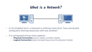
  • 1. What is a Network? • In its simplest form, a network is nothing more than “two connected computers sharing resources with one another.” • It is composed of two main aspects: o Physical Connection (wires, cables, wireless media) o Logical Connection (data transporting across the physical media)
  • 2. Some Basic Networking Rules • The computers in a network must use the same procedures for sending and receiving data. We call these communication protocols. • Data must be delivered uncorrupted. If it is corrupted, it’s useless. (There are Exceptions) • Computers in a network must be capable of determining the origin and destination of a piece of information, i.e., its IP and Mac Address.
  • 3. Types of Computer Networks (by Size) • Personal Area Network (PAN) • Local Area Network (LAN) • Wireless Local Area Network (WLAN) • Campus Area Network (CAN) • Metropolitan Area Network (MAN) • Wide Area Network (WAN)
  • 4. Network Architecture Client-Server Peer-to-Peer • All computers on the network are peers • No dedicated servers • There’s no centralized control over shared resources • Any device can share its resources as it pleases • All computers can act as either a client or a server • Easy to set-up, and common in homes and small businesses • The network is composed of client and servers • Servers provide resources • Clients receive resources • Servers provide centralized control over network resources (files, printers, etc.) • Centralizes user accounts, security, and access controls to simplify network administration • More difficult to setup and requires an IT administrator
  • 5. Why Build a Computer Network? • Before computer networks, people sent and received information by hand, using the postal service. This is slow and can be unreliable. • Computer networks enable faster, more efficient modes of communication, i.e., email, video conferencing, etc. • Computer networks and the sharing of electronic data encourage the use of standard policies and procedures. • Computer networks provide backup and recovery support for our data, i.e., redundancy. • Computer networks lead to cost savings.
  • 6. Personal Area Network (PAN) • Ultra-small networks used for personal use to share data from one device to another. • Can be wired (PAN) or wireless (WPAN): o USB o Bluetooth o NFC o ANT+ • Examples: o Smart Phone to Laptop o Smart Watch to Smart Phone o Smart Phone Hands-Free Car Calling o Heart Rate Monitor to Smart Phone
  • 7. Local Area Network (LAN) • A computer network within a small geographical area, such as a single room, building or group of buildings. • Considered to be self-contained: o All devices are directly connected via cables and/or short-range wireless technology. o Doesn’t require a leased telecommunications line from an Internet Service Provider (ISP). • Examples: o Home Network o Small Business or Office Network
  • 8. Wireless Local Area Network (WLAN) • A LAN that’s dependent on wireless connectivity or one that extends a traditional wired LAN to a wireless LAN. • Most home networks are WLANs.
  • 9. Campus Area Network (CAN) • A computer network of multiple interconnected LANs in a limited geographical area, such as a corporate business park, government agency, or university campus. • Typically owned or used by a single entity.
  • 10. Metropolitan Area Network (MAN) • A computer network that interconnects users with computer resources in a city. • Larger than a campus area network, but smaller than a wide area network.
  • 11. Wide Area Network (WAN) • A computer network that extends over a large geographical distance, typically multiple cities and countries. • WANs connect geographically distant LANs. • Typically use leased telecommunications lines from ISPs. • Examples: o The Internet o Corporate Offices in Different States
  • 12. Some Basic Networking Rules • The computers in a network must use the same procedures for sending and receiving data. We call these communication protocols. • Data must be delivered uncorrupted. If it is corrupted, it’s useless. (There are Exceptions) • Computers in a network must be capable of determining the origin and destination of a piece of information, i.e., its IP and Mac Address.
  • 13. What is a Network? • In its simplest form, a network is nothing more than “two connected computers sharing resources with one another.” • It is composed of two main aspects: o Physical Connection (wires, cables, wireless media) o Logical Connection (data transporting across the physical media)
  • 14. Computer Networking Protocols • Computers communicate with each other with network protocols. • Protocols are rules governing how machines exchange data and enable effective communication. • Some Everyday Examples • When you call somebody, you pick up the phone, ensure there is a dial tone, and if there is, you dial the number. • When you drive your car, you obey the rules of the road.
  • 15. Protocols Continued • Physical Protocols: describe the medium (wiring), the connections (RJ-45 port), and the signal (voltage level on a wire). • Logical Protocols: software controlling how and when data is sent and received to computers, supporting physical protocols. • Computer networks depend on many different types of protocols in order to work properly. • Example Common TCP/IP Suite of Protocols: o Web Communication: HTTP o E-mail: POP3, SMTP, IMAP o File Transfers: FTP
  • 16. The OSI Model What is it? The Open Systems Interconnection (OSI) Reference Model • A conceptual framework showing us how data moves throughout a network. • Developed by the International Organization for Standardization (ISO) in 1977. It’s Purpose • Gives us a guide to understanding how networks operate. It’s only a reference model, so don’t get wrapped up in the details. • Wasn’t implemented in the real world, TCP/IP is.
  • 17. The OSI Model Stack The OSI Model breaks down the complex task of computer-to-computer network communications into seven layers. Upper Layers (Host Layers) • Handled by the host computer and performs application-specific functions, such as data formatting, encryption, and connection management. Lower Layers (Media Layers) • Provide network-specific functions, such as routing, addressing, and flow control.
  • 18. The OSI Model Visualized
  • 20. The TCP/IP Model • The TCP/IP suite is the most commonly used protocol suite in the networking world. • It’s essentially the protocol suite in which the Internet was built. • It’s the standard for computer networking. • It is based on a 4-layer model that is similar to the OSI model. • History of TCP/IP: o Developed by the United States Department of Defense (DoD) in the early 1970s. o In 1982, the DOD declared TCP/IP as the standard for all military computer networking. o In 1984, broad adoption of TCP/IP began (IBM, AT&T, etc.).
  • 21. TCP/IP & OSI Models Side-by-Side
  • 22. MAC Addresses Media Access Control (MAC) • Physical address of the network adapter card • OSI Layer 2 (Data Link) Layer Address • TCP/IP Layer 1 (Network Interface) Layer Address Six bytes (48 bits), Usually Represented Hexadecimal • First three bytes (24 bits) are assigned by the IEEE to the manufacturer o Organizationally Unique Identifier (OUI) assigned by IEEE (ex: Dell or HP) • Last three bytes (24 bits) are usually assigned sequentially: o Unique Numbers 00:21:70:6f:06:f2 00-21-70-6F-06-F2 224 = ~16.7 Million Unique Addresses
  • 23. IP Addresses • An IP Address is a logical address used in order to uniquely identify a device on an IP network. • It’s a Network Layer address associated with routing. o OSI Layer 3: Network Layer o TCP/IP Layer 2: Internet Layer • There are two versions: o IP version 4 (IPv4) ▪ Example: 192.168.0.1 o IP version 6 (IPv6) ▪ Example: 2001:DB8:85A3:0:0:8A2E:370:7334 • We’ll be discussing both versions in this course.
  • 24. Comparing IP and MAC Addresses MAC Addresses IP Addresses • Network (OSI Layer 3) Addresses • Logical Addresses • Assigned in Operating System • Allows network-to-network communication via routers • WAN communication • Data Link (OSI Layer 2) Addresses • Physical Addresses • Physically burned on NIC • Allows internetwork communication via hubs, switches, and routers • Local LAN communication
  • 25. Half vs. Full Duplex Communication • Network communication will occur in either full or half duplex mode: o Half Duplex: Can send and receive data, but not at the same time. o Full Duplex: Can send and receive data simultaneously.
  • 26. Network Transmission Types • Unicast • Multicast • Broadcast
  • 30. Introduction to Ethernet • The most popular networking technology in the world! • Refers to a family of standards that define the physical and logical aspects of the world's most popular type of LAN. • The standard communications protocol for building a local area network (LAN). • Physical o Cabling, Connectors, Equipment, etc. • Logical o Network Access Method, i.e., Carrier Sense Multiple Access (CSMA)
  • 31. Physical vs. Logical Topologies Physical topologies describe the placement of network devices and how they are physically connected. Logical topologies describe how data flows throughout a network.
  • 32. Wired Network Topologies • Four Specific Topologies: o Bus o Ring o Star o Mesh
  • 33. Bus Topology • All devices are connected to a single coaxial network cable. o Devices are connected via a vampire tap or T-Connector. o Terminators are required at both ends of the cable to prevent signal bounce. o Antiquated technology. • Only one end device can be active on the network at a time. o Data signals travel in both directions and are received by all devices on the network. • A single break in the cable can take down the entire network.
  • 34. Ring Topology • All devices are connected in a circular fashion. • Each computer is connected to two other computers. • Data travels from node-to-node with each computer handling data, either unidirectional or bidirectional. • Each device (node) in the ring regenerates the signal, acting as a repeater. • Failure of a single node can take down the entire network. • Fiber Distributed Data Interface (FDDI) uses two counter-rotating ring topologies for redundancy.
  • 35. Star Topology • All devices are connected to a central connecting device, which is usually a switch. • Devices send data to the switch, which forwards it to the appropriate destination device. • Popular topology in today’s networks. • Used in most large and small networks. • Central device is a single point of failure.
  • 36. Mesh Topology • Each device is connected to every other device by separate cabling. • Highly redundant and fault-tolerance. • Expensive to install. • Commonly used in Enterprise Networks & WANs. • Two Types: o Partial Mesh o Full Mesh
  • 37. Wireless Network Topologies • Wireless networks utilize radio frequencies (RF) to communicate. • Three Specific Topologies: o Ad hoc o Infrastructure o Mesh
  • 38. Ad hoc • Peer-to-peer (P2P) wireless network where no wireless access point (WAP) infrastructure exits. • The devices communicate directly with one another. • Personal area networks (PANs) are a common example of Ad hoc wireless networks.
  • 39. Infrastructure • Wireless network that uses a wireless access point (WAP) as its central connecting device. • Infrastructure wireless networks (WLANs) are commonly used in homes and small offices.
  • 40. Mesh • Just like a wired mesh design, wireless mesh networks utilize several wireless access points (nodes) to create a robust wireless network that is: o Scalable o Self-Healing o Reliable (redundancy) • Common in larger homes and businesses.
  • 41. Network Interface Card (NIC) • The network adapter installed on your network device. • Provides the physical and electrical, light or radio frequency connections to the network media. • It can either be an expansion card, USB devices or built directly into the motherboard.
  • 42. Hubs • Used to Connect Devices Together Within a Network • Used in Early Networks; Replaced by Switches • “Multi-Port Repeater” o Traffic goes in one port and is repeated (broadcasted) out every other port o OSI Layer 1 Device o Dumb Network Device o Causes increased network collision errors • Much Less Efficient than a Switch • Legacy Equipment No Longer Used
  • 43. Switches • Connects Devices Together Just Like a Hub • Intelligent Network Device (OSI Layer 2) • Memorizes the MAC Address of Each Device Connected to It via a MAC Address Table, sometimes called a Content Addressable Memory (CAM) Table • Pays attention to Source and Destination MAC addresses during Communication Process • Use Application-Specific Integrated Circuitry (ASIC), which makes them Extremely Fast • Breaks up Collision Domains o Traffic Goes in One Port and Is Repeated out to Only Destination Port o Designed for High Bandwidth o Standard in Today’s Network Infrastructure
  • 44. Wireless Access Point (WAP) • A wireless access point (WAP) is a bridge that extends the wired network to the wireless network. • Just like a switch, it’s a Data Link Layer 2 device. • Note: A WAP is not a router.
  • 45. Wireless Ranger Extender • Extends the range of a wireless network by acting as a wireless repeater. • Rebroadcasts radio frequencies from the wireless network it is associated with
  • 46. Routers • Used to Connect Different Networks Together • Routes Traffic Between Networks using IP Addresses • Uses Intelligent Decisions (Routing Protocols) to Find the Best Way to Get a Packet of Information from One Network to Another. • Break Up Broadcast Domains • OSI Layer 3 Device o Layer 3 = Router o Layer 2 = Switch o Layer 1 = Hub
  • 47. Modems (Modulators/Demodulators) • Modems modulate one signal to another, such as analog to digital. • For example, modulating a telephone analog signal into a digital signal that a router can understand.
  • 48. Small Office Home Office (SOHO) Device • All-In-One Wireless Router with Expanded Capabilities: o Router, Wireless Access Point, Firewall, Switch, DHCP Server, NAT Device, File Server, etc.
  • 49. Media Converters • Like its name implies, it converts one media type to another. • Layer 1 Device: Performs physical layer signal conversion. • Ethernet to fiber optic media converters are commonly used.
  • 50. Firewalls • Firewalls are the foundation of a defense-in-depth network security strategy. • They protect your network from malicious activity on the Internet. • Prevent unwanted network traffic on different networks from accessing your network. • Firewalls do this by filtering data packets that go through them. • They can be a standalone network device or software on a computer system, meaning network-based (hardware) or host-based (software).
  • 51. Types of Firewalls Packet Filtering Firewalls • 1st Generation & Most Basic • Basic Filtering Rules Circuit-Level Firewalls • 2nd Generation • Monitors Valid/Invalid TCP Sessions Application Layer 7 (NGFW) Firewalls • 3rd Generation • Much more Advanced; Covered Later in Course
  • 52. DHCP Server • Dynamic Host Configuration Protocol (DHCP) Server • Automatically Assigns IP Addresses to Hosts • Makes Administering a Network Much Easier • An Alternative is Static IP addressing • We'll Talk More About DHCP Later in the Course
  • 53. Voice over IP (VoIP) Endpoints • Most phone systems run over IP networks via dedicated protocols, such as the Session Initiation Protocol (SIP), both in-home and office environments. • VoIP endpoint devices are hardware devices (phones) or software, such as Cisco Jabber, that allow you to make phone calls.
  • 54. Types of Network Cabling • Coaxial • Twisted Pair • Fiber Optic
  • 55. Ethernet Explained • Ethernet is a network protocol that controls how data is transmitted over a LAN. • It’s referred to as the Institute of Electrical and Electronics Engineers (IEEE) 802.3 Standard. • It supports networks built with coaxial, twisted-pair, and fiber-optic cabling. • The original Ethernet standard supported 10Mbps speeds, but the latest supports much faster gigabit speeds. • Ethernet uses CSMA/CD & CSMA/CA access methodology.
  • 56. Ethernet N<Signaling>-X Naming • Ethernet uses an “xx Base T” naming convention: 10Base-T o N: Signaling Rate, i.e., Speed of the cable. o <Signaling>: Signaling Type: Baseband (Base) communication. o X: Type of cable (twisted pair or fiber).
  • 57. Twisted Pair Standards Cat Network Type Ethernet Standard Speed Max. Distance Cat 3 Ethernet 10Base-T 10Mbps 100 meters Cat 5 Fast Ethernet 100Base-TX 100Mbps 100 meters Cat 5e Gigabit Ethernet 1000Base-T 1Gbps 100 meters Cat 6 Gigabit Ethernet 10 Gigabit Ethernet 1000Base-T 10GBase-T 1Gbps 10Gbps 100 meters 55 meters Cat 6a 10 Gigabit Ethernet 10GBase-T 10Gbps 100 meters Cat 7 10 Gigabit Ethernet 10GBase-T 10Gbps 100 meters Cat: Copper Cabling Standard.
  • 58. Coaxial Cable • Antiquated technology used in the 1980s. Coaxial cables are rarely used today, except for cable modem connections. • Categorized as Radio Grade (RG) o RG-6: Used for modern cable TV and broadband cable modems. o RG-8: Used in early 10Base5 “Thick-net” Ethernet networks. o RG-58: Used in early 10Base2 “Thin-net” Ethernet networks. o RG-59: Used for closed-circuit TV (CCTV) networks • Metallic shield helps protect against electromagnetic interference (EMI)
  • 59. Coaxial Cable Connectors F-Connector • Screw-on connection • RG-6 Cable TV and Broadband Cable Applications. BNC Connector • Tension spring twist-on connection • RG-8 “Thick-net” and RG-58 “Thin- net” network applications.
  • 60. Twisted Pair Copper Cabling • 4 Twisted Pairs of Wires with RJ-45 Connector • Balanced pair operation o + & - Signals o Equal & Opposite Signal • Why are they twisted? o To Help Reduce Interference • Crosstalk • Noise (Electromagnetic Interference) • Security concerns o Signal Emanations • 100 Meters Maximum Distance o Signal Attenuation
  • 61. Shielded vs. Unshielded & EMI • Unshielded Twisted Pair (UTP) o More susceptible to electromagnetic interference (EMI). • Shielded Twisted Pair (STP) o Less susceptible to EMI & Crosstalk (if each pair shielded). • Electromagnetic Interference o The disruption of an electronic device's operation when it's in the vicinity of an electromagnetic field caused by another electronic device (manufacturing equipment, microwave ovens, etc.).
  • 62. Roles of Twists • Increased twists per inch: o Reduces Crosstalk o Increases Signals o Supports Faster Speeds
  • 63. Twisted Pair Standards Cat: Copper Cabling Standard. Cat Network Type Ethernet Standard Speed Max. Distance Frequency Cat 3 Ethernet 10Base-T 10Mbps 100 meters 16 MHz Cat 5 Fast Ethernet 100Base-TX 100Mbps 100 meters 100 MHz Cat 5e Gigabit Ethernet 1000Base-T 1Gbps 100 meters 100 MHz Cat 6 Gigabit Ethernet 10 Gigabit Ethernet 1000Base-T 10GBase-T 1Gbps 10Gbps 100 meters 55 meters 250 MHz Cat 6a 10 Gigabit Ethernet 10GBase-T 10Gbps 100 meters 500 MHz Cat 7 10 Gigabit Ethernet 10GBase-T 10Gbps 100 meters 600 MHz
  • 64. Other Copper Cable Connectors DB-25 • 25-pin connection previously commonly used for serial printer connections. DB-9 • 9-pin connection used for serial connections on networking devices RJ-11 • 4-pin connection used for telephone connections.
  • 65. TIA/EIA 568A & 568B Wiring Standards • Industry-standard that specifies the pin arrangement for RJ-45 connectors. • Two Standards: • 568A & 568B • 568B is newer and the recommended standard. • Either can be used. • Why are standards important? o Lower Costs o Increase Interoperability o Easier Maintenance
  • 66. Straight-Through & Crossover Cables Crossover Cable • Connecting “Like” Devices o Router to Router o Computer to Computer Straight-Through Cable • Connecting “Unlike” Devices o Computer to Switch o Switch to Router
  • 67. Which Twisted Pairs Are Used? Gigabit & 10 Gigabit Ethernet Cat 5e & Faster All Four Pairs Used: • Supports bi-directional data transmission on each pair of wires. Ethernet & Fast Ethernet Cat 3 and Cat 5 Only Green and Orange Pairs Used: • Pins 1, 2, 3, and 6 o One Pair to Transmit Data (TX) o One Pair to Receive Data (RX)
  • 68. The Plenum • The plenum is the open space above the ceiling or below a raised floor. • A “plenum space” is the part of a building that enables air circulation by providing pathways for heated/air-conditioned and return airflows at a higher pressure than normal. • All network cabling placed in the plenum should be “plenum-rated.”
  • 69. Non-Plenum-Rated & Fire Hazard • Non-plenum cable or polyvinyl chloride (PVC) cable is often much less expensive than plenum-rated cable. • When PVC burns or smolders, it releases toxic fumes into the air (Hydrochloric Acid and Dioxin). • The plenum air return would unknowingly circulate toxic air throughout an office. • Sprinkler systems typically can’t access the plenum area. • Building codes often require Plenum Rated cable installed through any plenum space.
  • 70. Plenum-Rated Cables • Plenum-rated cables have a special insulation that has low smoke, low flame and non-toxic characteristics. • Coated with nonflammable materials that minimize toxic fumes: o Teflon o Fluorinated ethylene polymer (FEP) o Low-Smoke PVC
  • 71. Fiber Optic Cabling • Glass or plastic fiber that carries light (photons) o High Bandwidth: Photons travel faster than electrons. o Long Distances: Less attenuation. o Immune to Electromagnetic Interference (EMI) o Doesn’t Emanate Signals • Two Types o Multi-mode Fiber (MMF) • Shorter Distances (LAN / Building-to-Building) • Up to 2 Kilometers o Single-mode Fiber (SMF) • More expensive than multi-mode • Longer Distances (WAN / Across Town) • Up to 200 Kilometers Informational Note: 9-micron Single-Mode Fiber can travel 75 miles at 400 Gbps
  • 72. MMF versus SMF Single-Mode Fiber (SMF) • A single direct photon of light travels through the cable, which allows greater distances and speed. • Smaller Core: 8 to 10 microns Multi-Mode Fiber (MMF) • Many photons of light travel through the cable at once, and bounce off the walls, which reduces the distance and speed. • Larger Core: 50 to 62.5 microns
  • 73. Fiber Optic Cable Connectors Lucent Connector (LC) • Small form-factor design that has a flange on the top, similar to an RJ-45 connector. • Commonly used in MMF & SMF gigabit and 10-gigabit Ethernet networks. Straight Tip (ST) • BNC style connector with a half-twist bayonet locking mechanism. • Was used in MMF networks but not commonly used anymore. Subscriber Connector (SC) • Square connector that uses a push-pull connector similar to A/V equipment. • Commonly used in MMF & SMF gigabit Ethernet networks. Mech. Transfer Register Jack (MTRJ) • Similar to the RJ-45 connector, and houses two fiber optics cables. • Designed for MMF networks.
  • 74. Why use Fiber? • Fiber cable is more expensive than twisted pair, as is the equipment • But you can perform much longer network cable runs with fiber. o 100m versus up to 200 Kilometers • So you have decreased network equipment costs o Switches, routers, etc. • Plus fiber is: o Immune to EMI and signal emanations o Has lower signal attenuation o Making it more reliable and secure • Costs are steadily decreasing as more people adopt fiber
  • 75. Cable Selection Criteria Cost Constraints • What is your budget? Transmission Speed Requirements • How fast does your network need to be? • 10Mbps, 100Mbps, 1Gbps, 10Gbps? Distance Requirements • Electrical signals degrade relatively quickly (100 meters) • Fiber can transmit over long distances Noise & Interference Immunity (Crosstalk, EMI, Security) • Interference is all around us: power cables, microwaves, mobile phones, motors, etc.
  • 76. Layer 7 – Application Layer • Where users interact with the computer. • Acts as an interface between an application and end-user protocols. • Provides an interface to communicate with the network (Outlook, Chrome, etc.). • Applications don’t reside in the application layer but instead interfaces with application- layer protocols. • Example Application Layer Protocols: o E-Mail: IMAP4, POP3, SMTP o Web Browsers: HTTP, HTTPS o Remote Access: SSH, Telnet
  • 77. Layer 6 – Presentation Layer • Ensures that data transferred from one system’s Application Layer can be read by the Application Layer on another one. • Provides character code conversion, data compression, and data encryption/decryption. • Example: Google Chrome HTML converted to ASCII Format.
  • 78. Layer 6 – Presentation Layer • Example Layer 6 File Formats: o Web Browser: HTML, XML, JavaScript o Graphics Files: JPEG, GIF, PNG o Audio/Video: MPEG, MP3 o Encryption: TLS, SSL o Text/Data: ASCII, EBCDIC
  • 79. Layer 5 - Session Layer • Responsible for setting up, managing, and then tearing down sessions between network devices. • Ensures data from different application sessions are kept separate. • Utilizes Application Program Interfaces (APIs) to communicate with TCP/IP protocols. • Coordinates communication between systems. o Start, Stop, Restart
  • 80. Layer 5 - Session Layer Can provide three different methods of communication between devices: • Simplex: One-way communication between two devices, like listening to a radio station. • Half Duplex: Two-way communication between two devices, but only one device can communicate at a time. • Full Duplex: Two-way communication between two devices, where both sides can communicate at the same time.
  • 81. Layer 4 - Transport Layer • Ensures data is delivered error-free and in sequence. • Segments data and reassembles correctly. • Can be connection-oriented or connectionless. • Considered the “Post Office” Layer o TCP (Transmission Control Protocol) o UDP (User Datagram Protocol) o Covered in detail in the next section.
  • 82. Layer 4 - Transport Layer Responsible for two data flow control measures: • Buffering o Stores data in memory buffers until destination device is available. • Windowing o Allows devices in session to determine the “window” size of data segments sent.
  • 83. Layer 3 - Network Layer • The “Routing” Layer • Provides logical addressing (IP Addressing) and routing services. • Places two IP addresses into a packet: o Source Address & Destination IP Address • Internet Protocol (IP) o The primary network protocol used on the Internet, IPv4, IPv6 Logical Addresses
  • 84. Layer 3 - Network Layer Types of Packets at Network Layer: • Data Packets o Routed Internet Protocol (IP) data packets. • IPv4 & IPv6 • Route-Update Packets o Routing protocols designed to update neighboring routers with router information for path determination. o RIP, OSPF, EIGRP, etc. Layer 3 Devices & Protocols: • Routers & Multi-Layer Switches • IPv4 & IPv6 • Internet Control Message Protocol (ICMP), i.e., Ping
  • 85. Layer 2 – Data Link Layer • The “Switching” Layer • Ensures that messages are delivered to the proper device on a LAN using hardware addresses. o MAC (Media Access Control) Address o Only concerned with the local delivery of frames on the same network. • Responsible for packaging the data into frames for the physical layer. • Translates messages from the Network layer into bits for the Physical layer.
  • 86. Layer 2 – Data Link Layer Has two Sub-Layers • Logical Link Control (LLC) Layer o Error Control and Flow Control • Detect and correct corrupted data frames. • Limits amount of data sent so devices aren’t overwhelmed. • Media Access Control (MAC) Layer o Physical Addressing (MAC Address) • 48-Bit MAC Address burned on NIC. o Logical Topology and Media Access o Ethernet, Token Ring, etc. o CSMA/CD & CSMA/CA
  • 87. Layer 1 – Physical Layer Defines the physical and electrical medium for network communication: • Sending and receiving bits (1 or 0) • Encoding Signal Types o Electricity, radio waves, light • Network Cabling, Jacks, Patch Panels, etc. o Copper or Fiber • Physical Network Topology o Star, Mesh, Ring, etc. • Ethernet IEEE 802.3 Standard • Layer 1 Equipment o Hubs, Media Converters, Modems It’s responsible for the network hardware and physical topology.
  • 88. OSI Encapsulation & De-Encapsulation
  • 89. OSI Encapsulation & De-Encapsulation
  • 90. What is TCP/IP? • Transmission Control Protocol/Internet Protocol • Commonly called the Internet Protocol suite because it was designed for the Internet, but LANs use it too. • First Two Protocols Defined in the Suite Were: o TCP & IP, hence TCP/IP • Similar to the OSI Model, but Simpler: o OSI is Conceptual o TCP/IP was Implemented
  • 91. TCP/IP Protocols Layer Protocols Application FTP, TFTP, DNS, HTTP(S), TLS/SSL, SSH, POP3, IMAP4, NTP, Telnet, SMTP, SNMP Transport TCP, UDP and Ports Internet IP Addressing (Routing), ICMP, ARP Network Interface Ethernet, Token Ring These protocols work together to provide communication, management, diagnostics, and troubleshooting for a TCP/IP network.
  • 92. Network Access Methods Token Ring • The Token o Passed between devices on the network. o Only devices with the token can send data. o Token prevents network collisions. CSMA • Carrier Sense o Checks network for communication. • Multiple Access o Multiple devices using the network. • Collision Detection o Wired Network • Collision Avoidance o Wireless Network
  • 93. Address Resolution Protocol (ARP) • Resolves IP address to MAC Addresses • Finds the hardware address of a host from a know IP address o And vice versa (RARP) ARP Command: arp -a
  • 94. ARP Diagram If a computer knows a device’s IP address but not its MAC address, it’ll send a broadcast message to all devices on the LAN asking which device is assigned that MAC address.
  • 95. The Internet Protocol (IP) • An OSI Layer 3 protocol that defines routing and logical addressing of packets that allow data to traverse WANs and the Internet. • It specifies the formatting of packets and the logical addressing schema o IP addresses: IPv4 and IPv6 • Its job is to connect different OSI Layer 2 (switched) networks together. • Provides end-to-end connectivity from one Layer 2 network to another via routers.
  • 96. The Internet Protocol (IP) • It’s connectionless and, therefore, unreliable (similar to UDP). o No continued connection. • Each packet sent is independent of each other packet. o TCP and other protocols provide a means to reassemble them properly. o Packets don’t always follow the same path to their destination. o They’re sent via the most efficient route. • Doesn’t provide any error recovery or sequencing functionality. o That’s the job of other protocols.
  • 97. Internet Control Message Protocol (ICMP) • OSI Layer 3 Internet Protocol (IP) companion “error reporting” protocol within the TCP/IP suite of protocols. • Just like IP, it’s connectionless. • Used to generate error messages to the source IP address when network issues prevent the delivery of a packet. • Typically used by routers to report packet delivery issues, and, most importantly, it can report errors but not correct them. • Commonly used by IT administrators to troubleshoot network connections with command-line utilities, including ping, pathping, and traceroute. • For IPv6, it is also used for: o Neighbor Solicitation and Advertisement Messages (Similar to ARP) o Router Solicitation and Advertisement Messages
  • 98. (Some) ICMP Message Types • Echo Request, Echo Reply: Tests destination accessibility and status. A host sends an Echo Request and listens for a corresponding Echo Reply. Commonly done using the ping command. • Destination Unreachable: Sent by a router when it can’t deliver an IP packet. • Source Quench: Sent by a host or router if it’s receiving too much data than it can handle. The message requests that the source reduces its rate of data transmission. • Redirect Message: Sent by a router if it receives a packet that should have been sent to a different router. The message includes the IP address to which future packets should be sent and is used to optimize the routing. • Time Exceeded: Sent by a router if a packet has reached the maximum limit of routers through which it can travel. • Router Advertisement, Router Solicitation (IPv6): Allow hosts to discover the existence of routers. Routers periodically multicast their IP addresses via Router Advertisement messages. Hosts may also request a router IP address by broadcasting a Router Solicitation message, then wait for a router to reply with a Router Advertisement.
  • 99. Understanding Protocols, Ports, and Sockets Protocols • Computers communicate with each other with network protocols. • Protocols are rules governing how machines exchange data and enable effective communication. • In an operating system (OS), a protocol runs as a process or service. Ports • Ports are logical constructs that bind a unique port number to a protocol process or service. Sockets • Sockets are a combination of an IP address and a port number, for example, 192.168.1.1:80.
  • 100. Why We Need Ports and Sockets • Computers require ports because of network application multitasking. • Because a computer may have only one IP address, it needs ports to differentiate network protocols and services running on it. • TCP/IP has 65,536 ports available Port Type Port Numbers Description Well Known Ports 0 – 1023 Assigned to well-known protocols. Registered Ports 1024 – 49,151 Registered to specific protocols. Dynamic Ports 49,152 – 65,535 Not registered and used for any purpose.
  • 101. Protocols & Port Numbers Service, Protocol, or Application Port Number(s) TCP or UDP FTP (File Transfer Protocol) 20, 21 TCP Secure FTP (SFTP) 22 TCP SSH (Secure Shell Protocol) 22 TCP Telnet 23 TCP SMTP (Simple Mail Transfer Protocol) 25 TCP DNS (Domain Name System) 53 UDP DHCP (Dynamic Host Configuration Protocol) 67, 68 UDP TFTP (Trivial File Transfer Protocol) 69 UDP HTTP (Hypertext Transfer Protocol) 80 TCP POP3 (Post Office Protocol version 3) 110 TCP
  • 102. Protocols & Port Numbers Service, Protocol, or Application Port Number(s) TCP or UDP NTP (Network Time Protocol) 123 UDP IMAP4 (Internet Message Access Protocol version 4) 143 TCP SNMP (Simple Network Management Protocol) 161 UDP LDAP (Lightweight Directory Access Protocol) 389 TCP HTTPS (Hypertext Transfer Protocol Secure) 443 TCP Server Message Block (SMB) 445 TCP LDAPS (Lightweight Directory Access Protocol Secure) 636 TCP RDP (Remote Desktop Protocol) 3389 TCP ITU Telecommunication Standardization Sector A/V Recommendation (H.323) 1720 TCP Session Initiation Protocol (SIP) 5060, 5061 TCP
  • 103. TCP vs. UDP Transport Layer Protocols • TCP (Transmission Control Protocol): Connection-Oriented • UDP (User Datagram Protocol): Connectionless TCP is the most widely used Transport Layer protocol because it is connection-oriented, which provides packet delivery reliability, i.e., guaranteed delivery. UDP, being connectionless, is considered to be unreliable; however, it is more lightweight than TCP and often used for streaming or real-time data.
  • 104. TCP Reliability • TCP utilizes the following features to ensure reliable delivery of data. o 3-Way Handshake creates a virtual connection between the source and destination before data is sent. o Acknowledgment is required before the next segment is sent. o Checksum that detects corrupted data. o Sequence Numbers that detect missing data and reassemble them in the correct order. o Retransmission that will retransmit lost or corrupt data. • Note: TCP header is 20 bytes in size, whereas the UDP header is only 8 bytes.
  • 105. TCP Three-Way Handshake • A connection must be established before data is transmitted, called the three-way handshake. o SYN → SYN / ACK → ACK • Creates a Virtual Connection Between 2 Devices
  • 106. “Best Effort” UDP • A scaled-down, economic version of TCP o Connectionless & Unreliable o No Data Retransmissions o “Best Effort” • Faster than TCP o Smaller Header & Connectionless • Primarily used for protocols that favor: • Low-Latency, i.e., Faster Speeds • Can Tolerate Data Loss
  • 107. “Best Effort” UDP • Example UDP Use-Cases o VoIP Phone Calls o Live Video Streams o Live Audio Streams o Online Gaming o Certain Network Management Protocols o DNS o DHCP o NTP
  • 108. Application Layer Management Protocols • Domain Name System (DNS) • Dynamic Host Configuration Protocol (DHCP) • Network Time Protocol (NTP) • Simple Network Management Protocol (SNMP) • Lightweight Directory Access Protocol (LDAP) • LDAP Secure (LDAPS) • Server Message Block (SMB)
  • 109. Domain Name System (DNS) • Protocol that is used to resolve a domain name to its corresponding IP address o InstructorAlton.com → 162.0.232.236 • Uses TCP port 53 by default • We’ll be discussing DNS in detail in the DNS Network Services section of this course: o DNS Hierarchy o DNS Record Types o Name Resolution Port: 53 Transport Layer Protocol: UDP
  • 110. Dynamic Host Configuration Protocol (DHCP) • Protocol that automatically assigns IP address configurations to devices on a network: o IP Address o Subnet Mask o Default Gateway o DNS Server • We’ll be discussing how DHCP works in detail in the Assigning IP Addresses section of this course • Uses two UDP ports 67 and 68 by default Ports: 67, 68 Transport Layer Protocol: UDP
  • 111. Network Time Protocol (NTP) • Protocol that automatically synchronizes a system’s time with a network time server. o Important for time-dependent network applications and protocols. o If a system is configured with the incorrect time, it may not be able to access network services. o Authentication will often fail if time isn’t properly synchronized between devices. • Uses TCP port 123 by default. Port: 123 Transport Layer Protocol: TCP
  • 112. Simple Network Management Protocol (SNMP) • Protocol used to monitor and manage network devices • Allows admins to monitor and manage network devices and traffic. • Allows network devices to communicate information about their state: o Memory o CPU o Bandwidth • Uses TCP port 161 by default Port: 161 Transport Layer Protocol: TCP
  • 113. Lightweight Directory Access Protocol (LDAP) • Protocol that provides a means to access and query directory service systems: o Usernames, Passwords, Computer Accounts, etc. • Typically Unix/Linux-based or Microsoft Active Directory-based • Uses TCP 389 by default Port: 389 Transport Layer Protocol: TCP
  • 114. LDAP Secure (LDAPS) • LDAP over SSL • A secure version of LDAP that utilizes SSL to encrypt LDAP network traffic • Uses TCP port 636 by default Port: 636 Transport Layer Protocol: TCP
  • 115. Server Message Block (SMB) • Network and file sharing protocol commonly used in Microsoft environments • Allows systems to share their files and printers with other systems • Uses TCP port 445 by default Port: 445 Transport Layer Protocol: TCP
  • 116. Application Layer Remote Communication Protocols • Telnet • Secure Shell (SSH) • Remote Desktop Protocol (RDP)
  • 117. Telnet • Legacy protocol used to “insecurely” connect to a remote host o Data is transferred in clear text, so it’s considered insecure o Largely replaced by SSH • Today it’s primarily used to access managed network devices, such as routers via a serial connection • Use TCP Port 23 by default Port: 23 Transport Layer Protocol: TCP
  • 118. Secure Shell (SSH) • A cryptographic protocol that’s used to securely connect to a remote host o Utilizes a terminal console o Typically Unix and Linux Machines, but also available on Windows and Mac OS • Encrypts data with public key infrastructure (PKI), making it secure o Considered secure replacement for Telnet • Uses TCP port 22 by default Port: 22 Transport Layer Protocol: TCP
  • 119. Remote Desktop Protocol (RDP) • A Microsoft protocol that allows users to remotely connect to, view, and control a remote computer from a Windows desktop. • Built into the Microsoft operating system. • Uses TCP port 3389 by default Port: 3389 Transport Layer Protocol: TCP
  • 120. Application Layer File Transfer Protocols • File Transfer Protocol (FTP) • Secure File Transfer Protocol (SFTP) • Trivial File Transfer Protocol (TFTP)
  • 121. File Transfer Protocol (FTP) • Legacy protocol used to transfer files between systems o Slowly being replaced by Secure FTP (SFTP) • Can authenticate with a username and password or utilize anonymous logins • Data is transferred in clear text, so it’s considered insecure • Full-featured functionality: o View, list, add, delete, etc. files and folders • Uses two TCP ports by default: o Port 20 for Data: Data Transfers o Port 21 for Control: Commands Ports: 20, 21 Transport Layer Protocol: TCP
  • 122. Secure File Transfer Protocol (SFTP) • A secure cryptographic version of FTP that uses SSH to provide encryption services. o Provides file transfer over SSH • Uses TCP port 22 by default (same port as SSH) Port: 22 Transport Layer Protocol: TCP
  • 123. Trivial File Transfer Protocol (TFTP) • A bare-bones version of FTP used for simple downloads o Doesn’t support authentication o Doesn’t support directory navigation • Requires that you request the exact file (and location) • Often used to transfer software images for routers and switches during upgrades • Utilizes UDP port 69 by default Port: 69 Transport Layer Protocol: UDP
  • 124. Application Layer Email Protocols • Simple Mail Transfer Protocol (SMTP) • Post Office Protocol Version 3 (POP3) • Internet Message Access Protocol (IMAP)
  • 125. Simple Mail Transfer Protocol (SMTP) • Email protocol that is used to deliver emails from an email client (Outlook) to a destination email server • Can be configured to use encryption (recommended) or plain text • Uses TCP Port 25 by default Port: 25 Transport Layer Protocol: TCP
  • 126. Post Office Protocol Version 3 (POP3) • Email protocol that is used to retrieve emails from an email server • Can be configured to use encryption (recommended) or plain text • Uses TCP Port 110 by default Port: 110 Transport Layer Protocol: TCP
  • 127. Internet Message Access Protocol (IMAP) • Another email protocol that is quickly replacing POP3 • Allows users to access email on servers and either read the email on the server or download the email to the client machine • Popular when a user accesses email from multiple different devices • Web-based email clients, such as Gmail, use IMAP • Uses TCP port 143 by default Port: 143 Transport Layer Protocol: TCP
  • 128. Application Layer Web Browser Protocols • Hypertext Transfer Protocol (HTTP) • HTTP Secure (HTTPS)
  • 129. Hypertext Transfer Protocol (HTTP) • Protocol that provides browsing services for the World Wide Web (WWW) o Retrieves the content of a web page from a web server o Requests are made in hypertext markup language (HTML) and returned to your browser in that format • Data is sent in plain text • Uses TCP Port 80 by default Port: 80 Transport Layer Protocol: TCP
  • 130. HTTP Secure (HTTPS) • HTTP over Secure Socket Layer (SSL) or Transport Layer Security (TLS) • A secure version of HTTP that utilizes SSL/TLS to encrypts HTTP content • Utilizes Public Key Infrastructure (PKI) • Uses TCP Port 443 by default Port: 443 Transport Layer Protocol: TCP
  • 131. Understanding IPv4 Addresses • An IP Address is a logical address used in order to uniquely identify a device on an IP network. • It’s a Network Layer Address • There are Two Versions: o IP version 4 (IPv4) o IP version 6 (IPv6) • This lesson focuses on IPv4, and we’ll discuss IPv6 later in the course.
  • 132. IPv4 Address Anatomy • Made up of 32 binary bits, which can be divided into a network portion and a host portion with the help of a subnet mask. o The 32 binary bits are broken into four octets (1 octet = 8 bits). o Each octet is converted to decimal and separated by a period (dot). o For this reason, an IP address is said to be expressed in dotted decimal format.
  • 133. IPv4 Address Anatomy First Octet Second Octet Third Octet Fourth Octet 192 . 168 . 1 . 131 11000000 . 10101000 . 00000001 . 10000011 8 bits 8 bits 8 bits 8 bits
  • 134. Network and Host Portion • An IP address is broken down into two parts: • Network Address • Uniquely identifies each network • Your Street Name: 7682 Wilshire Drive • Host Address • Uniquely identifies each machine on a network • Your House Address: 7682 Wilshire Drive • Network Address + Host Address = IP Address • Wilshire Drive 7682
  • 135. IPv4 Address Components • Each device on a network is assigned an IP address, subnet mask and default gateway: o IP Address: Unique logical address assigned to each device on a network. o Subnet Mask: Used by the device to determine what subnet it’s on, specifically the network and host portions of the IP address. o Default Gateway: The IP address of a network’s router that allows devices on the local network to communicate with other networks.
  • 136. Basics of Binary Math Lecture Goals • Convert Binary to Decimal • Convert Decimal to Binary
  • 137. Basics of Binary Math Why is it important? We need to know basic binary math to perform subnetting, as well as to understand how IPv4 addresses work. Remember This 128 + 64 + 32 + 16 + 8 + 4 + 2 + 1 = 255
  • 138. What is the binary 11111111 in decimal? 128 64 32 16 8 4 2 1 Binary 1 1 1 1 1 1 1 1 Decimal 128 + 64 + 32 + 16 + 8 + 4 + 2 + 1 = 255 Decimal Add the number where there is a “1”. Add zero, when there is a “0”.
  • 139. What is the binary 10101010 in decimal? Add the number where there is a “1”. Add zero, when there is a “0”. 128 64 32 16 8 4 2 1 Binary 1 0 1 0 1 0 1 0 Decimal 128 + 0 + 32 + 0 + 8 + 0 + 2 + 0 = 170 Decimal
  • 140. What is the binary 10000011 in decimal? Add the number where there is a “1”. Add zero, when there is a “0”. 128 64 32 16 8 4 2 1 Binary 1 0 0 0 0 0 1 1 Decimal 128 + 0 + 0 + 0 + 0 + 0 + 2 + 1 = 131 Decimal
  • 141. What’s 192 in binary? Start adding the numbers from left to right until you achieve the decimal amount you are looking for! 128 64 32 16 8 4 2 1 Binary 1 1 0 0 0 0 0 0 = 11000000 Decimal 128 + 64 + 0 + 0 + 0 + 0 + 0 + 0 = 192 Decimal
  • 142. What’s 202 in binary? Start adding the numbers from left to right until you achieve the decimal amount you are looking for! 128 64 32 16 8 4 2 1 Binary 1 1 0 0 1 0 1 0 = 11001010 Decimal 128 + 64 + 0 + 0 + 8 + 0 + 2 + 0 = 202 Decimal
  • 143. What’s 54 in binary? Start adding the numbers from left to right until you achieve the decimal amount you are looking for! 128 64 32 16 8 4 2 1 Binary 0 0 1 1 0 1 1 0 = 00110110 Decimal 0 + 0 + 32 + 16 + 0 + 4 + 2 + 0 = 54 Decimal
  • 144. IP Address Conversion Process 192. 168. 32. 4 Dotted Decimal 11000000. 10101000. 00100000. 00000100 Binary 1st Octet 2nd Octet 3rd Octet 4th Octet Whether you are given an IP address in dotted-decimal or binary format, follow the respective process above for each octet one by one until you have completed the process.
  • 145. Binary Math Worksheet ANSWER KEY BINARY MATH WORKSHEET ANSWER KEY CONVERSION CHART 128 + 64 + 32 + 16 + 8 + 4 + 2 + 1 1. CONVERT 11110000 TO DECIMAL 128 64 32 16 8 4 2 1 Binary 1 1 1 1 0 0 0 0 = Decimal 128 + 64 + 32 + 16 + 0 + 0 + 0 + 0 = 240 Decimal 2. CONVERT 10011001 TO DECIMAL 128 64 32 16 8 4 2 1 Binary 1 0 0 1 1 0 0 1 = Decimal 128 + 0 + 0 + 16 + 8 + 0 + 0 + 1 = 153 Decimal 3. CONVERT 01101011 TO DECIMAL 128 64 32 16 8 4 2 1 Binary 0 1 1 0 1 0 1 1 = Decimal 0 + 64 + 32 + 0 + 8 + 0 + 2 + 1 = 107 Decimal 4. CONVERT 10110011 TO DECIMAL 128 64 32 16 8 4 2 1 Binary 1 0 1 1 0 0 1 1 = Decimal 128 + 0 + 32 + 16 + 0 + 0 + 2 + 1 = 179 Decimal 5. CONVERT 240 TO BINARY 128 64 32 16 8 4 2 1 Binary 1 1 1 1 0 0 0 0 = 11110000 Binary Decimal 128 + 64 + 32 + 16 + 0 + 0 + 0 + 0 =
  • 146. Binary Math Worksheet ANSWER KEY 6. CONVERT 163 TO BINARY 128 64 32 16 8 4 2 1 Binary 1 0 1 0 0 0 1 1 = 10100011 Binary Decimal 128 + 0 + 32 + 0 + 0 + 0 + 2 + 1 = 7. CONVERT 94 TO BINARY 128 64 32 16 8 4 2 1 Binary 0 1 0 1 1 1 1 0 = 01011110 Binary Decimal 0 + 64 + 0 + 16 + 8 + 4 + 2 + 0 = 8. CONVERT 225 TO BINARY 128 64 32 16 8 4 2 1 Binary 1 1 1 0 0 0 0 1 = 11100001 Binary Decimal 128 + 64 + 32 + 0 + 0 + 0 + 0 + 1 = 9. CONVERT THE FOLLOWING IP ADDRESS FROM DECIMAL TO BINARY 192.168.98.18 • 192 = 11000000 • 168 = 10101000 • 98 = 01100010 • 18 = 00010010 Binary Format: 11000000. 10101000. 01100010. 00010010 10. CONVERT THE FOLLOWING IP ADDRESS FROM BINARY TO DECIMAL 01000010.11010010.11000110.11000101 • 01000010 = 66 • 11010010 = 210 • 11000110 = 198 • 11000101 = 197 Dotted Decimal Format: 66.210.198.197
  • 147. Binary Math Worksheet BINARY MATH WORKSHEET CONVERSION CHART 128 + 64 + 32 + 16 + 8 + 4 + 2 + 1 1. CONVERT 11110000 TO DECIMAL 128 64 32 16 8 4 2 1 Binary = Decimal + + + + + + + = 2. CONVERT 10011001 TO DECIMAL 128 64 32 16 8 4 2 1 Binary = Decimal + + + + + + + = 3. CONVERT 01101011 TO DECIMAL 128 64 32 16 8 4 2 1 Binary = Decimal + + + + + + + = 4. CONVERT 10110011 TO DECIMAL 128 64 32 16 8 4 2 1 Binary = Decimal + + + + + + + = 5. CONVERT 240 TO BINARY 128 64 32 16 8 4 2 1 Binary = Decimal + + + + + + + =
  • 148. Binary Math Worksheet 6. CONVERT 163 TO BINARY 128 64 32 16 8 4 2 1 Binary = Decimal + + + + + + + = 7. CONVERT 94 TO BINARY 128 64 32 16 8 4 2 1 Binary = Decimal + + + + + + + = 8. CONVERT 225 TO BINARY 128 64 32 16 8 4 2 1 Binary = Decimal + + + + + + + = 9. CONVERT THE FOLLOWING IP ADDRESS FROM DECIMAL TO BINARY 192.168.98.18 10. CONVERT THE FOLLOWING IP ADDRESS FROM BINARY TO DECIMAL 01000010.11010010.11000110.11000101
  • 149. IPv4 Address Classes (Simplified) Class Network Bits Host Bits Address Range A 8 24 1.0.0.0 – 126.255.255.255 B 16 16 128.0.0.0 – 191.255.255.255 C 24 8 192.0.0.0 – 223.255.255.255
  • 151. IPv4 Address Classes (Detailed) Class Leading Bits Network Bits Remaining Bits Number of Networks Hosts Per Network Default Subnet Mask Class A 0 (1-126) 8 24 128 (27) 16,777,216 (224) 255.0.0.0 Class B 10 (128-191) 16 16 16,384 (214) 65,536(216) 255.255.0.0 Class C 110 (192-223) 24 8 2,097,152 (221) 256(28) 255.255.255.0 Class D (multicast) 1110 (224-239) Not Defined Not Defined Not Defined Not Defined Not Defined Class E (reserved) 1111 (240-255) Not Defined Not Defined Not Defined Not Defined Not Defined
  • 152. Default Subnet Masks • The Subnet Mask tells you which portion of the IP address identifies the network and which portion identifies the host. • Below are default Class A, B, and C Subnet Masks.
  • 153. Let’s Practice What class are the following IP Addresses? • IP Address: 9.10.40.15 • Subnet Mask: 255.0.0.0 • IP Address: 135.240.110.100 • Subnet Mask: 255.255.0.0 • IP Address: 196.200.10.5 • Subnet Mask: 255.255.255.0
  • 154. CIDR Notation • CIDR: Classless Inter-Domain Routing o A methodology for subnetting o “Slash” Notation tells you how many bits are associated with the Subnet Mask • A shortcut way of telling us what the Subnet Mask is: o /8 = 11111111.00000000.00000000.00000000 o /8 = 255.0.0.0 • 192.168.1.0 /24 = 255.255.255.0 • 10.1.0.0 /16 = 255.255.0.0 • 196.10.10.0/25 = 255.255.255.128
  • 155. Understanding the Power of 2 • We use the power of 2 in IP addressing and subnetting. • It’s important to memorize the power of 2. 21 = 2 22 = 4 23 = 8 24 = 16 25 = 32 26 = 64 27 = 128 28 = 256 29 = 512 210 = 1,024 211 = 2,048 212 = 4,096
  • 156. Using Power of 2 to Determine Network Hosts • Hosts Per Network = 2h – 2, where h is the number of host bits available. • We subtract two because each network includes a network address and broadcast address that are not available for use by network end devices.
  • 157. Public versus Private IP Addresses Private IP Addresses • “Unregistered” – Free for Use by Anybody! • Designed for Use within Private Internal Networks • Can Be Used Over and Over Again • Cannot be Used or Routed on a Public Network • Utilizes NAT to “Speak” to Public Networks, i.e., the Internet! Public IP Addresses • Original Design of Internet • “Registered” Public IP Addresses • Assigned by an ISP to a Business or Home • Must be Globally Unique o Web Servers o DNS Servers o Routers • By the Early 1990s, the World was Running out of Public IP Addresses • Private IP Addresses & Network Address Translation (NAT) were Born!
  • 158. Private IP Address Ranges Class IP Address Range Network ID(s) (CIDR Notation) Number of Addresses A 10.0.0.0 – 10.255.255.255 10.0.0.0 /8 • 1 Private Class A Network 16,777,216 IP Addresses Per Network ID B 172.16.0.0 – 172.31.255.255 172.16.0.0 – 172.31.0.0 /16 • 16 Private Class B Networks 65,534 IP Addresses Per Network ID C 192.168.0.0 – 192.168.255.255 192.168.0.0 – 192.168.255.0 /24 • 256 Private Class C Networks 254 IP Addresses Per Network ID
  • 159. The Loopback Address • 127.0.0.0 to 127.255.255.255 is reserved for loopback, i.e., a host’s own address, also known as the localhost address. o 127.0.0.1 is typically configured as the default loopback address on operating systems. • Used for diagnostics purposes to check that TCP/IP is correctly installed on a host’s operating system. o When a process creates a packet destined to the loopback address, the operating system loops it back to itself without it ever interfacing with the NIC. o Data sent on the loopback is forwarded by the operating system to a virtual network interface within the operating system. • If you can successfully ping 127.0.0.1 or any IP within the loopback range, then TCP/IP on your computer is properly working. o Ping 127.0.0.1 o Ping localhost o Ping loopback
  • 160. Why Subnet? • Using default Class A, B and C subnets (called Classful IP Addressing) is inefficient: o Wastes unused IP Addresses (Public IP Addresses) • Allows you to create multiple logical networks that exist within a single Class A, B, or C network. o Breaks up larger networks into multiple smaller sub-networks, which are called subnets • Allows for more efficient routing via router summarization. • Increased network security!
  • 161. Fixed Length Subnetting • We will be learning about fixed-length subnetting, known as a fixed- length subnet mask (FLSM). • There is also variable-length subnetting (VLSM), which is beyond the scope of this beginner’s course.
  • 162. Class C Subnetting Example • You’re the network administrator for the Computer Science department at a university. • You’re setting up four new lecture halls that must have their own 60-person wireless network. • You’ve been assigned the 200.15.178.0 Class C Network by the university, that supports 254 hosts per network by default. • How do you break up this one Class C network into 4 smaller networks that support 60 host IP addresses per network? • You subnet it. • Subnetting allows your to breakup a larger network into smaller networks (subnets). Subnet 1 (Lecture Hall 1) • 200.15.178.0/26 • 62 Hosts Subnet 2 (Lecture Hall 2) • 200.15.178.64/26 • 62 Hosts Subnet 3 (Lecture Hall 3) • 200.15.178.128/26 • 62 Hosts Subnet 4 (Lecture Hall 4) • 200.15.178.192/26 • 62 Hosts 200.15.178.0 Class C Network (254 Hosts)
  • 163. Process of Subnetting • We borrow host bits to create more sub-networks (subnets) from a Class A, B, or C network. • When you borrow hosts bits: o You create additional sub-networks, i.e., subnets o You also decrease the amount of host IP addresses available to use
  • 164. How to Create Subnets • Borrow bits from the host portion of an IP address • Each bit we borrow is equal to 21 Subnets • Borrow 1 Host Bit = 21 = 2 • Borrow 2 Host Bits = 22 = 4 • Borrow 3 Host Bits = 23 = 8 • Borrow 4 Host Bits = 24 = 16 • Etc.
  • 166. Subnetting Questions • To Create a Subnet, Answer the Following Questions: o How many subnets are needed? o How many hosts do you need per subnet?
  • 167. Class C Possible Subnets Binary (N.N.N.H) Decimal CIDR # Subnets (2x) Block Size (2y) # Hosts (2y - 2) N.N.N.00000000 255.255.255.0 /24 20 = 1 28 = 256 28 – 2 = 254 N.N.N.10000000 255.255.255.128 /25 21 = 2 27 = 128 27 – 2 = 126 N.N.N.11000000 255.255.255.192 /26 22 = 4 26 = 64 26 – 2 = 62 N.N.N.11100000 255.255.255.224 /27 23 = 8 25 = 32 25 – 2 = 30 N.N.N.11110000 255.255.255.240 /28 24 = 16 24 = 16 24 – 2 = 14 N.N.N.11111000 255.255.255.248 /29 25 = 32 23 = 8 23 – 2 = 6 N.N.N.11111100 255.255.255.252 /30 26 = 64 22 = 4 22 – 2 = 2 Number of Subnets (2x) • X = number of host bits we borrow to create subnets Block Size (2y) • Y = number of remaining host bits left that are used for the subnet IP addresses Hosts per Subnet (2y – 2) • There are two addresses per network (or subnet) that we cannot use to assign to hosts on that network: o Network Address: This is the address used to uniquely identify the network (or subnet). o Broadcast Address: Address reserved for broadcast communication on the network.
  • 168. Class B Possible Subnets Binary (N.N.H.H) Decimal CIDR # Subnets (2x) Block Size (2y) # Hosts (2y - 2) N.N.00000000.00000000 255.255.0.0 /16 20 = 1 216 = 65,536 216 – 2 = 65,534 N.N.10000000.00000000 255.255.128.0 /17 21 = 2 215 = 32,768 215 – 2 = 32,766 N.N.11000000.00000000 255.255.192.0 /18 22 = 4 214 = 16,384 214 – 2 = 16,382 N.N.11100000.00000000 255.255.224.0 /19 23 = 8 213 = 8,192 213 – 2 = 8,190 N.N.11110000.00000000 255.255.240.0 /20 24 = 16 212 = 4,096 212 – 2 = 4,094 N.N.11111000.00000000 255.255.248.0 /21 25 = 32 211 = 2,048 211 – 2 = 2,046 N.N.11111100.00000000 255.255.252.0 /22 26 = 64 210 = 1,024 210 – 2 = 1,022 N.N.11111110.00000000 255.255.254.0 /23 27 = 128 29 = 512 29 – 2 = 510 N.N.11111111.00000000 255.255.255.0 /24 28 = 256 28 = 256 28 – 2 = 254 N.N.11111111.10000000 255.255.255.128 /25 29 = 512 27 = 128 27 – 2 = 126 N.N.11111111.11000000 255.255.255.192 /26 210 = 1,024 26 = 64 26 – 2 = 62 N.N.11111111.11100000 255.255.255.224 /27 211 = 2,048 25 = 32 25 – 2 = 30 N.N.11111111.11110000 255.255.255.240 /28 212 = 4,096 24 = 16 24 – 2 = 14 N.N.11111111.11111000 255.255.255.248 /29 213 = 8,192 23 = 8 23 – 2 = 6 N.N.11111111.11111100 255.255.255.252 /30 214 = 16,384 22 = 4 22 – 2 = 2
  • 169. Class A Possible Subnets Binary (N.H.H.H) Decimal CIDR # Subnets (2x) Block Size (2y) # Hosts (2y - 2) N.00000000.00000000.00000000 255.0.0.0 /8 20 = 1 222 = 16,777,216 222 – 2 = 16,777,214 N.10000000.00000000.00000000 255.128.0.0 /9 21 = 2 223 = 8,388,608 223 – 2 = 8,388,606 N.11000000.00000000.00000000 255.192.0.0 /10 22 = 4 222 = 4,194,304 222 – 2 = 4,194,302 N.11100000.00000000.00000000 255.224.0.0 /11 23 = 8 221 = 2,097,152 221 – 2 = 2,097,150 N.11110000.00000000.00000000 255.240.0.0 /12 24 = 16 220 = 1,048,576 220 – 2 = 1,048,574 N.11111000.00000000.00000000 255.248.0.0 /13 25 = 32 219 = 524,288 219 – 2 = 524,286 N.11111100.00000000.00000000 255.252.0.0 /14 26 = 64 218 = 262,144 218 – 2 = 262,142 N.11111110.00000000.00000000 255.254.0.0 /15 27 = 128 217 = 131,072 217 – 2 = 131,070 N.11111111.00000000.00000000 255.255.0.0 /16 28 = 256 216 = 65,536 216 – 2 = 65,534 N.11111111.10000000.00000000 255.255.128.0 /17 29 = 512 215 = 32,768 215 – 2 = 32,766 N.11111111.11000000.00000000 255.255.192.0 /18 210 = 1,024 214 = 16,384 214 – 2 = 16,382 N.11111111.11100000.00000000 255.255.224.0 /19 211 = 2,048 213 = 8,192 213 – 2 = 8,190 N.11111111.11110000.00000000 255.255.240.0 /20 212 = 4,096 212 = 4,096 212 – 2 = 4,094 N.11111111.11111000.00000000 255.255.248.0 /21 213 = 8,192 211 = 2,048 211 – 2 = 2,046 N.11111111.11111100.00000000 255.255.252.0 /22 214 = 16,384 210 = 1,024 210 – 2 = 1,022 N.11111111.11111110.00000000 255.255.254.0 /23 215 = 32,768 29 = 512 29 – 2 = 510 N.11111111.11111111.00000000 255.255.255.0 /24 216 = 65,536 28 = 256 28 – 2 = 254 N.11111111.11111111.10000000 255.255.255.128 /25 217 = 131,072 27 = 128 27 – 2 = 126 N.11111111.11111111.11000000 255.255.255.192 /26 218 = 262,144 26 = 64 26 – 2 = 62 N.11111111.11111111.11100000 255.255.255.224 /27 219 = 524,288 25 = 32 25 – 2 = 30 N.11111111.11111111.11110000 255.255.255.240 /28 220 = 1,048,576 24 = 16 24 – 2 = 14 N.11111111.11111111.11111000 255.255.255.248 /29 221 = 2,097,152 23 = 8 23 – 2 = 6 N.11111111.11111111.11111100 255.255.255.252 /30 222 = 4,194,304 22 = 4 22 – 2 = 2
  • 170. Subnet Calculation Table (2x) Host Bits Borrowed 2x Number of Subnets Created 1 21 2 2 22 4 3 23 8 4 24 16 5 25 32 6 26 64 7 27 128 8 28 256 9 29 512 10 210 1,024 11 211 2,048 12 212 4,096 Etc.…
  • 171. Subnet Hosts & Addresses Calculation Table (2Y) Host Bits Left 2y Addresses per Subnet (2y) Hosts per Subnet (2y – 2) 1 21 2 0 2 22 4 2 3 23 8 6 4 24 16 14 5 25 32 30 6 26 64 62 7 27 128 126 8 28 256 254 9 29 512 510 10 210 1,024 1,022 11 211 2,048 2,046 12 212 4,096 4,094
  • 172. Subnetting Reference Material Subnetting Reference Tables POWER OF 2’S TABLE 21 = 2 22 = 4 23 = 8 24 = 16 25 = 32 26 = 64 27 = 128 28 = 256 29 = 512 210 = 1,024 211 = 2,048 212 = 4,096 213 = 8,192 214 = 16,384 215 = 32,768 216 = 65,536 DEFAULT SUBNET MASK Class Format Default Subnet Mask A network.host.host.host 255.0.0.0 B network.network.host.host 255.255.0.0 C network.network.network.host 255.255.255.0 BINARY MATH TABLE 128 64 32 16 8 4 2 1 1 1 1 1 1 1 1 1
  • 173. Subnetting Reference Material SUBNET MASK TABLE Binary Decimal 00000000 0 10000000 128 11000000 192 11100000 224 11110000 240 11111000 248 11111100 252 SUBNET CALCULATION TABLE (2X ) Host Bits Borrowed 2x Number of Subnets Created 1 21 2 2 22 4 3 23 8 4 24 16 5 25 32 6 26 64 7 27 128 8 28 256 9 29 512 10 210 1,024 11 211 2,048 12 212 4,096 SUBNET HOSTS & ADDRESSES CALCULATION TABLE (2Y ) Host Bits Left 2y Hosts per Subnet (2y – 2) Addresses per Subnet (2y) 1 21 0 2 2 22 2 4 3 23 6 8 4 24 14 16 5 25 30 32 6 26 62 64 7 27 126 128 8 28 254 256 9 29 510 512 10 210 1,022 1,024 11 211 2,046 2,048 12 212 4,094 4,096
  • 174. Subnetting Reference Material CLASS C POSSIBLE SUBNET MASKS Binary (N.N.N.H) Decimal CIDR # Subnets (2x ) Block Size (2y ) # Hosts (2y - 2) N.N.N.00000000 255.255.255.0 /24 20 = 1 28 = 256 28 – 2 = 254 N.N.N.10000000 255.255.255.128 /25 21 = 2 27 = 128 27 – 2 = 126 N.N.N.11000000 255.255.255.192 /26 22 = 4 26 = 64 26 – 2 = 62 N.N.N.11100000 255.255.255.224 /27 23 = 8 25 = 32 25 – 2 = 30 N.N.N.11110000 255.255.255.240 /28 24 = 16 24 = 16 24 – 2 = 14 N.N.N.11111000 255.255.255.248 /29 25 = 32 23 = 8 23 – 2 = 6 N.N.N.11111100 255.255.255.252 /30 26 = 64 22 = 4 22 – 2 = 2 CLASS B POSSIBLE SUBNET MASKS Binary (N.N.H.H) Decimal CIDR # Subnets (2x ) Block Size (2y ) # Hosts (2y - 2) N.N.00000000.00000000 255.255.0.0 /16 20 = 1 216 = 65,536 216 – 2 = 65,534 N.N.10000000.00000000 255.255.128.0 /17 21 = 2 215 = 32,768 215 – 2 = 32,766 N.N.11000000.00000000 255.255.192.0 /18 22 = 4 214 = 16,384 214 – 2 = 16,382 N.N.11100000.00000000 255.255.224.0 /19 23 = 8 213 = 8,192 213 – 2 = 8,190 N.N.11110000.00000000 255.255.240.0 /20 24 = 16 212 = 4,096 212 – 2 = 4,094 N.N.11111000.00000000 255.255.248.0 /21 25 = 32 211 = 2,048 211 – 2 = 2,046 N.N.11111100.00000000 255.255.252.0 /22 26 = 64 210 = 1,024 210 – 2 = 1,022 N.N.11111110.00000000 255.255.254.0 /23 27 = 128 29 = 512 29 – 2 = 510 N.N.11111111.00000000 255.255.255.0 /24 28 = 256 28 = 256 28 – 2 = 254 N.N.11111111.10000000 255.255.255.128 /25 29 = 512 27 = 128 27 – 2 = 126 N.N.11111111.11000000 255.255.255.192 /26 210 = 1,024 26 = 64 26 – 2 = 62 N.N.11111111.11100000 255.255.255.224 /27 211 = 2,048 25 = 32 25 – 2 = 30 N.N.11111111.11110000 255.255.255.240 /28 212 = 4,096 24 = 16 24 – 2 = 14 N.N.11111111.11111000 255.255.255.248 /29 213 = 8,192 23 = 8 23 – 2 = 6 N.N.11111111.11111100 255.255.255.252 /30 214 = 16,384 22 = 4 22 – 2 = 2
  • 175. Subnetting Reference Material CLASS A POSSIBLE SUBNET MASKS Binary (N.H.H.H) Decimal CIDR # Subnets (2x ) Block Size (2y ) # Hosts (2y - 2) N.00000000.00000000.00000000 255.0.0.0 /8 20 = 1 222 = 16,777,216 222 – 2 = 16,777,214 N.10000000.00000000.00000000 255.128.0.0 /9 21 = 2 223 = 8,388,608 223 – 2 = 8,388,606 N.11000000.00000000.00000000 255.192.0.0 /10 22 = 4 222 = 4,194,304 222 – 2 = 4,194,302 N.11100000.00000000.00000000 255.224.0.0 /11 23 = 8 221 = 2,097,152 221 – 2 = 2,097,150 N.11110000.00000000.00000000 255.240.0.0 /12 24 = 16 220 = 1,048,576 220 – 2 = 1,048,574 N.11111000.00000000.00000000 255.248.0.0 /13 25 = 32 219 = 524,288 219 – 2 = 524,286 N.11111100.00000000.00000000 255.252.0.0 /14 26 = 64 218 = 262,144 218 – 2 = 262,142 N.11111110.00000000.00000000 255.254.0.0 /15 27 = 128 217 = 131,072 217 – 2 = 131,070 N.11111111.00000000.00000000 255.255.0.0 /16 28 = 256 216 = 65,536 216 – 2 = 65,534 N.11111111.10000000.00000000 255.255.128.0 /17 29 = 512 215 = 32,768 215 – 2 = 32,766 N.11111111.11000000.00000000 255.255.192.0 /18 210 = 1,024 214 = 16,384 214 – 2 = 16,382 N.11111111.11100000.00000000 255.255.224.0 /19 211 = 2,048 213 = 8,192 213 – 2 = 8,190 N.11111111.11110000.00000000 255.255.240.0 /20 212 = 4,096 212 = 4,096 212 – 2 = 4,094 N.11111111.11111000.00000000 255.255.248.0 /21 213 = 8,192 211 = 2,048 211 – 2 = 2,046 N.11111111.11111100.00000000 255.255.252.0 /22 214 = 16,384 210 = 1,024 210 – 2 = 1,022 N.11111111.11111110.00000000 255.255.254.0 /23 215 = 32,768 29 = 512 29 – 2 = 510 N.11111111.11111111.00000000 255.255.255.0 /24 216 = 65,536 28 = 256 28 – 2 = 254 N.11111111.11111111.10000000 255.255.255.128 /25 217 = 131,072 27 = 128 27 – 2 = 126 N.11111111.11111111.11000000 255.255.255.192 /26 218 = 262,144 26 = 64 26 – 2 = 62 N.11111111.11111111.11100000 255.255.255.224 /27 219 = 524,288 25 = 32 25 – 2 = 30 N.11111111.11111111.11110000 255.255.255.240 /28 220 = 1,048,576 24 = 16 24 – 2 = 14 N.11111111.11111111.11111000 255.255.255.248 /29 221 = 2,097,152 23 = 8 23 – 2 = 6 N.11111111.11111111.11111100 255.255.255.252 /30 222 = 4,194,304 22 = 4 22 – 2 = 2
  • 176. Subnetting a Class C Network #1 Details & Requirements You’ve been assigned a 192.168.1.0/24 Class C network, and you need to create two subnets from it. How many host bit do we need to borrow? 1 host bit, 21 = 2 Subnets How many host addresses per subnet? 7 host bits left, 27 = 128 Addresses / Subnet 27 - 2= 126 Addresses / Subnet What are the valid subnets? 192.168.1.0 and 192.168.1.128 New Subnet Mask? 11111111.11111111.11111111.10000000 255.255.255.128 or /25 Binary (N.N.N.H) Decimal CIDR # Subnets (2x) Block Size (2y) # Hosts (2y - 2) N.N.N.00000000 255.255.255.0 /24 20 = 1 28 = 256 28 – 2 = 254 N.N.N.10000000 255.255.255.128 /25 21 = 2 27 = 128 27 – 2 = 126 N.N.N.11000000 255.255.255.192 /26 22 = 4 26 = 64 26 – 2 = 62 N.N.N.11100000 255.255.255.224 /27 23 = 8 25 = 32 25 – 2 = 30 N.N.N.11110000 255.255.255.240 /28 24 = 16 24 = 16 24 – 2 = 14 N.N.N.11111000 255.255.255.248 /29 25 = 32 23 = 8 23 – 2 = 6 N.N.N.11111100 255.255.255.252 /30 26 = 64 22 = 4 22 – 2 = 2 Subnet #1 #2 Network Address 192.168.1.0 192.168.1.128 First Host IP 192.168.1.1 192.168.1.129 Last Host IP 192.168.1.126 192.168.1.254 Broadcast Address 192.168.1.127 192.168.1.255
  • 177. Visualizing Subnetting a Class C Network #1 Network Simplified View Network Detailed View
  • 178. Subnetting a Class C Network #2 Details & Requirements You’ve been assigned a 192.168.1.0/24 Class C network, and you need to create four subnets from it. How many host bit do we need to borrow? 2 host bits, 22 = 4 Subnets How many host addresses per subnet? 6 host bits left, 26 = 64 Addresses / Subnet 26 - 2= 62 Addresses / Subnet What are the valid subnets? 192.168.1.0, 192.168.1.64, 192.168.1.128, 192.168.1.192 New Subnet Mask? 11111111.11111111.11111111.11000000 255.255.255.192 or /26 Binary (N.N.N.H) Decimal CIDR # Subnets (2x) Block Size (2y) # Hosts (2y - 2) N.N.N.00000000 255.255.255.0 /24 20 = 1 28 = 256 28 – 2 = 254 N.N.N.10000000 255.255.255.128 /25 21 = 2 27 = 128 27 – 2 = 126 N.N.N.11000000 255.255.255.192 /26 22 = 4 26 = 64 26 – 2 = 62 N.N.N.11100000 255.255.255.224 /27 23 = 8 25 = 32 25 – 2 = 30 N.N.N.11110000 255.255.255.240 /28 24 = 16 24 = 16 24 – 2 = 14 N.N.N.11111000 255.255.255.248 /29 25 = 32 23 = 8 23 – 2 = 6 N.N.N.11111100 255.255.255.252 /30 26 = 64 22 = 4 22 – 2 = 2 Subnet Network /Subnet Address Host IP Addresses Broadcast Address 1 192.168.1.0 1 thru 62 192.168.1.63 2 192.168.1.64 65 thru 126 192.168.1.127 3 192.168.1.128 129 thru 190 192.168.1.191 4 192.168.1.192 193 thru 254 192.168.1.255
  • 179. Visualizing Subnetting a Class C Network #2 Network Simplified & Detail Views