Microcontrollers
Microcontroller
Please note thatmany diagrams used in this presentation have been taken from different sources. I am very thankful to the resource
providers as these items have rendered clarity to discussions.
2.
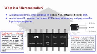
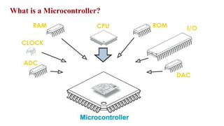
What is aMicrocontroller?
● A microcontroller is a small computer on a single VLSI integrated circuit chip.
● A microcontroller contains one or more CPUs along with memory and programmable
input/output peripherals.
Very-large-scale integration
(VLSI) is the process of creating
an integrated circuit (IC) by
combining thousands of
transistors into a single chip.
VLSI began in the 1970s when
complex semiconductor and
communication technologies
were being developed. The
microprocessor is also a VLSI
device.
A transistor is a semiconductor
device used to amplify or switch
electrical signals and power. It is one
of the basic building blocks of
modern electronics. It is composed
of semiconductor material, usually
with at least three terminals for
connection to an electronic circuit.
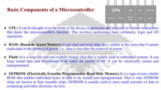
Basic Components ofa Microcontroller
● CPU: It can be thought of as the brain of the device. It processes and responds to various instructions
that direct the microcontroller's function. This involves performing basic arithmetic, logic and I/O
operations.
● RAM: (Random Access Memory) It can read and write data. It is volatile in the sense that it cannot
retain data in the absence of power; i.e., data is lost after the removal of power.
● Flash: It is a long-life and non-volatile storage chip that is widely used in embedded systems. It can
keep stored data and information even when the power is off. It can be electrically erased and
reprogrammed.
● EEPROM: (Electrically Erasable Programmable Read Only Memory) It is a type of non-volatile
ROM that enables individual bytes of data to be erased and reprogrammed. That is why EEPROM
chips are known as byte erasable chips. EEPROM is usually used to store small amounts of data in
computing and other electronic devices.
5.
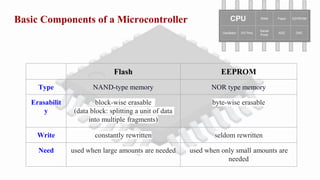
Basic Components ofa Microcontroller
Flash EEPROM
Type NAND-type memory NOR type memory
Erasabilit
y
block-wise erasable
(data block: splitting a unit of data
into multiple fragments)
byte-wise erasable
Write constantly rewritten seldom rewritten
Need used when large amounts are needed used when only small amounts are
needed
6.
Basic Components ofa Microcontroller
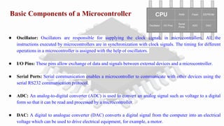
● Oscillator: Oscillators are responsible for supplying the clock signals in microcontrollers. All the
instructions executed by microcontrollers are in synchronization with clock signals. The timing for different
operations in a microcontroller is assigned with the help of oscillators.
● I/O Pins: These pins allow exchange of data and signals between external devices and a microcontroller.
● Serial Ports: Serial communication enables a microcontroller to communicate with other devices using the
serial RS232 communication protocol.
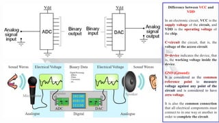
● ADC: An analog-to-digital converter (ADC) is used to convert an analog signal such as voltage to a digital
form so that it can be read and processed by a microcontroller.
● DAC: A digital to analogue converter (DAC) converts a digital signal from the computer into an electrical
voltage which can be used to drive electrical equipment, for example, a motor.
7.
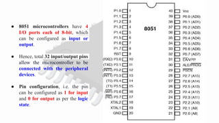
● 8051 microcontrollershave 4
I/O ports each of 8-bit, which
can be configured as input or
output.
● Hence, total 32 input/output pins
allow the microcontroller to be
connected with the peripheral
devices.
● Pin configuration, i.e. the pin
can be configured as 1 for input
and 0 for output as per the logic
state.
8.
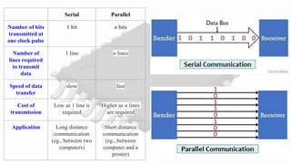
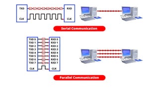
Serial Parallel
Number ofbits
transmitted at
one clock pulse
1 bit n bits
Number of
lines required
to transmit
data
1 line n lines
Speed of data
transfer
slow fast
Cost of
transmission
Low as 1 line is
required
Higher as n lines
are required
Application Long distance
communication
(eg., between two
computers)
Short distance
communication
(eg., between
computer and a
printer)
9.
Difference between VCCand
VDD
In an electronic circuit, VCC is the
supply voltage of the circuit, and
VDD is the operating voltage of
the chip.
C=circuit the circuit, that is, the
voltage of the access circuit.
D=device indicates the device, that
is, the working voltage inside the
device.
GND (Ground):
It is considered as the common
reference point to measure
voltage against any point of the
circuit and is considered to have
zero voltage.
It is also the common connection
that all electrical components must
connect to in one way or another in
order to complete the circuit.
10.
IC Packaging
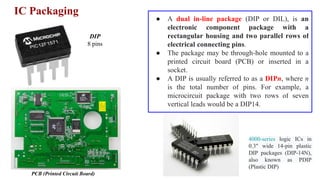
DIP
8 pins
PCB(Printed Circuit Board)
● A dual in-line package (DIP or DIL), is an
electronic component package with a
rectangular housing and two parallel rows of
electrical connecting pins.
● The package may be through-hole mounted to a
printed circuit board (PCB) or inserted in a
socket.
● A DIP is usually referred to as a DIPn, where n
is the total number of pins. For example, a
microcircuit package with two rows of seven
vertical leads would be a DIP14.
4000-series logic ICs in
0.3" wide 14-pin plastic
DIP packages (DIP-14N),
also known as PDIP
(Plastic DIP)
11.
IC Packaging
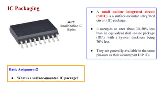
SOIC
Small OutlineIC
18 pins
● A small outline integrated circuit
(SOIC) is a surface-mounted integrated
circuit (IC) package.
● It occupies an area about 30–50% less
than an equivalent dual in-line package
(DIP), with a typical thickness being
70% less.
● They are generally available in the same
pin-outs as their counterpart DIP ICs.
Basic Assignment!!
● What is a surface-mounted IC package?
12.
IC Packaging
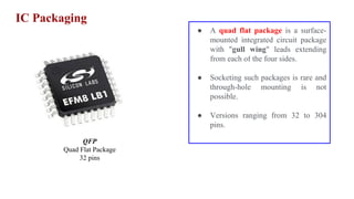
QFP
Quad FlatPackage
32 pins
● A quad flat package is a surface-
mounted integrated circuit package
with "gull wing" leads extending
from each of the four sides.
● Socketing such packages is rare and
through-hole mounting is not
possible.
● Versions ranging from 32 to 304
pins.
13.
IC Packaging
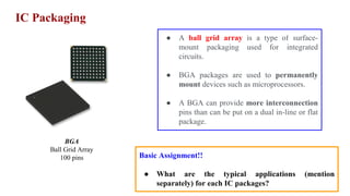
BGA
Ball GridArray
100 pins
● A ball grid array is a type of surface-
mount packaging used for integrated
circuits.
● BGA packages are used to permanently
mount devices such as microprocessors.
● A BGA can provide more interconnection
pins than can be put on a dual in-line or flat
package.
Basic Assignment!!
● What are the typical applications (mention
separately) for each IC packages?
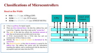
Classifications of Microcontrollers
Basedon Bus Width
● 8 bit (0 to 255) (ex: ATMega328P)
● 16 bit (0 to 65,535) (ex: ST10 series)
● 32 bit (0 to 429,49,67,295) (ex: STM32F10C8T6)
❏ A bus is a pathway for digital signals.
❏ There are three internal buses: the data bus, address bus, and
control bus. Together, these three make up the “system bus”.
❏ The width of the data bus reflects the maximum amount of
data that can be processed and delivered at one time.
❏ A 32-bit microcontroller has a 32-bit data bus and can
communicate 32-bits of data at a time.
❏ Whether the data is read or written is determined by the
control bus.
❏ The physical location of the data in memory is carried by the
address bus. The address bus carries only the information
regarding the address, and is synchronized with the data bus to
accomplish read/write tasks from the CPU.
16.
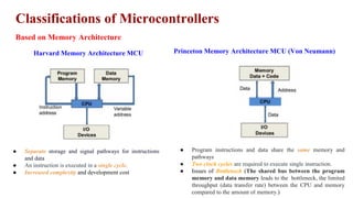
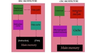
Classifications of Microcontrollers
Basedon Memory Architecture
Harvard Memory Architecture MCU Princeton Memory Architecture MCU (Von Neumann)
● Separate storage and signal pathways for instructions
and data
● An instruction is executed in a single cycle.
● Increased complexity and development cost
● Program instructions and data share the same memory and
pathways
● Two clock cycles are required to execute single instruction.
● Issues of Bottleneck (The shared bus between the program
memory and data memory leads to the bottleneck, the limited
throughput (data transfer rate) between the CPU and memory
compared to the amount of memory.)
17.
Classifications of Microcontrollers
Basedon Instruction Set
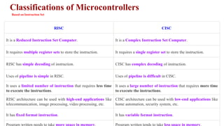
RISC CISC
It is a Reduced Instruction Set Computer. It is a Complex Instruction Set Computer.
It requires multiple register sets to store the instruction. It requires a single register set to store the instruction.
RISC has simple decoding of instruction. CISC has complex decoding of instruction.
Uses of pipeline is simple in RISC. Uses of pipeline is difficult in CISC.
It uses a limited number of instruction that requires less time
to execute the instructions.
It uses a large number of instruction that requires more time
to execute the instructions.
RISC architecture can be used with high-end applications like
telecommunication, image processing, video processing, etc.
CISC architecture can be used with low-end applications like
home automation, security system, etc.
It has fixed format instruction. It has variable format instruction.
Program written needs to take more space in memory. Program written tends to take less space in memory.
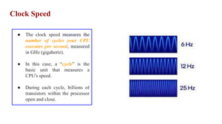
Clock Speed
● Theclock speed measures the
number of cycles your CPU
executes per second, measured
in GHz (gigahertz).
● In this case, a “cycle” is the
basic unit that measures a
CPU's speed.
● During each cycle, billions of
transistors within the processor
open and close.
22.
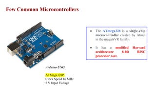
Few Common Microcontrollers
ArduinoUNO
ATMega328P
Clock Speed 16 MHz
5 V Input Voltage
● The ATmega328 is a single-chip
microcontroller created by Atmel
in the megaAVR family.
● It has a modified Harvard
architecture 8-bit RISC
processor core.
23.
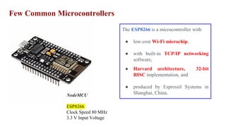
Few Common Microcontrollers
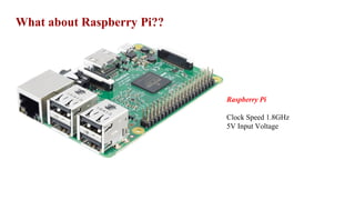
NodeMCU
ESP8266
ClockSpeed 80 MHz
3.3 V Input Voltage
The ESP8266 is a microcontroller with
● low-cost Wi-Fi microchip,
● with built-in TCP/IP networking
software,
● Harvard architecture, 32-bit
RISC implementation, and
● produced by Espressif Systems in
Shanghai, China.
24.
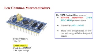
Few Common Microcontrollers
STM32F10C8T6
“BluePill”
ARM Cortex M3
Clock Speed 72MHZ
3.3V Input Voltage
The ARM Cortex-M is a group of
● Harvard architecture 32-bit
RISC ARM processor cores
● licensed by ARM Limited
● These cores are optimized for low-
cost and energy-efficient integrated
circuits
25.
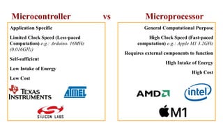
Microcontroller vs Microprocessor
ApplicationSpecific
Limited Clock Speed (Less-paced
Computation) e.g.: Arduino. 16MHz
(0.016GHz)
Self-sufficient
Low Intake of Energy
Low Cost
General Computational Purpose
High Clock Speed (Fast-paced
computation) e.g.: Apple M1 3.2GHz
Requires external components to function
High Intake of Energy
High Cost
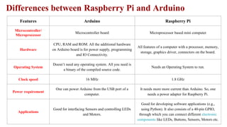
Features Arduino RaspberryPi
Microcontroller/
Microprocessor
Microcontroller board Microprocessor based mini computer
Hardware
CPU, RAM and ROM. All the additional hardware
on Arduino board is for power supply, programming
and IO Connectivity.
All features of a computer with a processor, memory,
storage, graphics driver, connectors on the board.
Operating System
Doesn’t need any operating system. All you need is
a binary of the compiled source code.
Needs an Operating System to run.
Clock speed 16 MHz 1.8 GHz
Power requirement
One can power Arduino from the USB port of a
computer.
It needs more more current than Arduino. So, one
needs a power adapter for Raspberry Pi.
Applications
Good for interfacing Sensors and controlling LEDs
and Motors.
Good for developing software applications (e.g.,
using Python). It also consists of a 40-pin GPIO,
through which you can connect different electronic
components like LEDs, Buttons, Sensors, Motors etc.
Differences between Raspberry Pi and Arduino
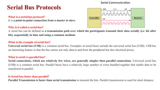
Serial Bus Protocols
Whatis a serial bus protocol?
It is a point-to-point connection from a master to slave.
Why is it called a serial bus?
A serial bus can be defined as a transmission path over which the participants transmit their data serially (i.e. bit after
bit), sequentially in time and using a common medium
What is the example of serial bus?
Universal serial bus (USB) is a common serial bus. Examples of serial buses include the universal serial bus (USB). USB has
an interesting feature in that the bus carries not only data to and from the peripheral but also electrical power.
What is serial vs parallel bus?
Serial connections, which use relatively few wires, are generally simpler than parallel connections. Universal serial bus
(USB) is a common serial bus. Parallel buses have a relatively large number of wires bundled together that enable data to be
transferred in parallel.
Is Serial bus faster than parallel?
Parallel Transmission is faster than serial transmission to transmit the bits. Parallel transmission is used for short distance.
31.
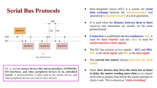
Serial Bus Protocols
I2C
(Inter-Integrated Circuit)
● Inter-integrated circuit (I2C) is a system for serial
data exchange between the microcontrollers and
specialized integrated circuits of a new generation.
● It is used when the distance between them is short
(receiver and transmitter are usually on the same
printed board).
● Connection is established via two conductors. One is
used for data transfer and the other is used for
synchronization (clock signal).
● The I2C bus consists of two signals − SCL and SDA.
SCL is the clock signal, and SDA is the data signal.
● The current bus master always generates the clock
signal.
● Some slave devices may force the clock low at times
to delay the master sending more data (or to require
more time to prepare data before the master attempts to
clock it out). This is known as “clock stretching”.
I2C is used to connect devices like microcontrollers, EEPROMs,
I/O interfaces, and other peripheral devices in an embedded
system. A microcontroller is often used as the master device, and
other peripheral devices are used as slave devices.
32.
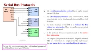
Serial Bus Protocols
SPI
(SerialPeripheral Interface)
❏ It is a serial communication protocol that is used to connect
low-speed devices.
❏ It is a full-duplex synchronous serial communication, which
means that data can be simultaneously transmitted from both
directions.
❏ The main advantage of the SPI is to transfer the data
without any interruption. Many bits can be sent or received
at a time in this protocol.
❏ In this protocol, devices are communicated in the master-
slave relationship.
❏ The simplest configuration of the Serial Peripheral Interface
(SPI) is a combination of a single slave and a single master.
But, one master device can control multiple slave devices.
To send data between microcontrollers and small peripherals such
as shift registers, sensors, and SD cards.
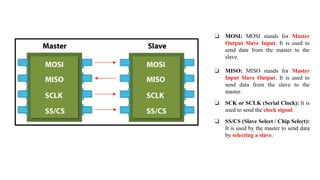
33.
❏ MOSI: MOSIstands for Master
Output Slave Input. It is used to
send data from the master to the
slave.
❏ MISO: MISO stands for Master
Input Slave Output. It is used to
send data from the slave to the
master.
❏ SCK or SCLK (Serial Clock): It is
used to send the clock signal.
❏ SS/CS (Slave Select / Chip Select):
It is used by the master to send data
by selecting a slave.
34.
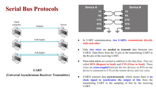
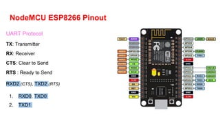
Serial Bus Protocols
UART
(UniversalAsynchronous Receiver/ Transmitter)
● In UART communication, two UARTs communicate directly
with each other.
● Only two wires are needed to transmit data between two
UARTs. Data flows from the Tx pin of the transmitting UART to
the Rx pin of the receiving UART.
● Two extra wires are needed in addition to the data lines. They are
called RTS (Request to Send) and CTS (Clear to Send). These
wires are cross-coupled between the two devices, so RTS on one
device is connected to CTS on the remote device and vice versa.
● UARTs transmit data asynchronously, which means there is no
clock signal to synchronize the output of bits from the
transmitting UART to the sampling of bits by the receiving
UART.
35.
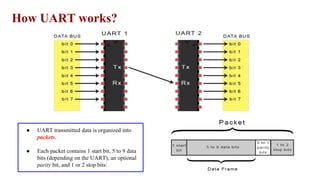
How UART works?
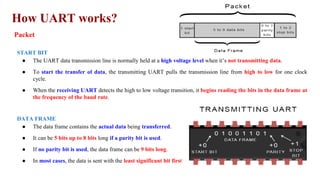
●UART transmitted data is organized into
packets.
● Each packet contains 1 start bit, 5 to 9 data
bits (depending on the UART), an optional
parity bit, and 1 or 2 stop bits:
36.
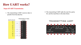
How UART works?
Stepsof UART Transmission
1. The transmitting UART receives data in
parallel from the data bus
2. The transmitting UART adds the start bit, parity
bit, and the stop bit(s) to the data frame:
37.
How UART works?
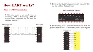
Stepsof UART Transmission
3. The entire packet is sent serially from the
transmitting UART to the receiving UART. The
receiving UART samples the data line at the pre-
configured baud rate:
4. The receiving UART discards the start bit, parity bit,
and stop bit from the data frame:
5. The receiving UART converts the serial data back into
parallel and transfers it to the data bus on the receiving end:
38.
How UART works?
Packet
STARTBIT
● The UART data transmission line is normally held at a high voltage level when it’s not transmitting data.
● To start the transfer of data, the transmitting UART pulls the transmission line from high to low for one clock
cycle.
● When the receiving UART detects the high to low voltage transition, it begins reading the bits in the data frame at
the frequency of the baud rate.
DATA FRAME
● The data frame contains the actual data being transferred.
● It can be 5 bits up to 8 bits long if a parity bit is used.
● If no parity bit is used, the data frame can be 9 bits long.
● In most cases, the data is sent with the least significant bit first.
39.
How UART works?
Packet
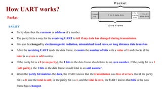
PARITY
●Parity describes the evenness or oddness of a number.
● The parity bit is a way for the receiving UART to tell if any data has changed during transmission.
● Bits can be changed by electromagnetic radiation, mismatched baud rates, or long distance data transfers.
● After the receiving UART reads the data frame, it counts the number of bits with a value of 1 and checks if the
total is an even or odd number.
● If the parity bit is a 0 (even parity), the 1 bits in the data frame should total to an even number. If the parity bit is a 1
(odd parity), the 1 bits in the data frame should total to an odd number.
● When the parity bit matches the data, the UART knows that the transmission was free of errors. But if the parity
bit is a 0, and the total is odd; or the parity bit is a 1, and the total is even, the UART knows that bits in the data
frame have changed.
40.
How UART works?
Packet
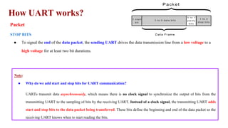
STOPBITS
● To signal the end of the data packet, the sending UART drives the data transmission line from a low voltage to a
high voltage for at least two bit durations.
Note:
● Why do we add start and stop bits for UART communication?
UARTs transmit data asynchronously, which means there is no clock signal to synchronize the output of bits from the
transmitting UART to the sampling of bits by the receiving UART. Instead of a clock signal, the transmitting UART adds
start and stop bits to the data packet being transferred. These bits define the beginning and end of the data packet so the
receiving UART knows when to start reading the bits.
41.
How UART works?
Note:
●What is baud rate?
When the receiving UART detects a start bit, it starts to read the incoming bits at a specific frequency known as the baud rate.
Baud rate is a measure of the speed of data transfer, expressed in bits per second (bps). Both UARTs must operate at about
the same baud rate. The baud rate between the transmitting and receiving UARTs can only differ by about 10% before the
timing of bits gets too far off.
● Should both UARTs have same configuration for packet structure?
Both UARTs must also must be configured to transmit and receive the same data packet structure.
42.
How UART works?
Advantagesand Disadvantages of UART
No communication protocol is perfect, but UARTs are pretty good at what they do. Here are some pros and cons to help you
decide whether or not they fit the needs of your project:
ADVANTAGES
● Only uses two wires
● No clock signal is necessary
● Has a parity bit to allow for error checking
● The structure of the data packet can be changed as long as both sides are set up for it
● Well documented and widely used method
DISADVANTAGES
● The size of the data frame is limited to a maximum of 9 bits
● Doesn’t support multiple slave or multiple master systems
● The baud rates of each UART must be within 10% of each other
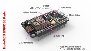
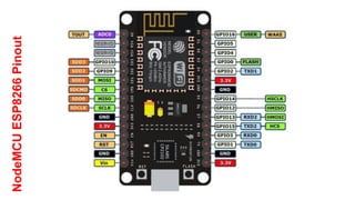
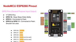
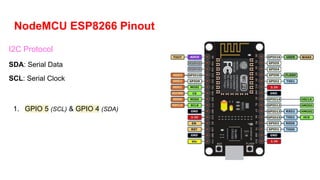
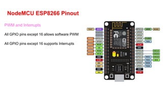
NodeMCU ESP8266 Pinout
GPIOPins (General Purpose Input Output)
● 17 GPIO Pins
● GPIO 16:- Deep Sleep Wake Ability
● GPIO 0:- Connected to Flash
● GPIO 6 to GPIO 11:- Connected to Flash.
Shouldn’t be used.
■ GPIO 06 : SDCLK
■ GPIO 07 : SDD0
■ GPIO 08 : SDD1
■ GPIO 09 : SDD2 (can be used)
■ GPIO 10 : SDD3 (can be used)
47.
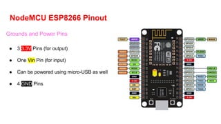
NodeMCU ESP8266 Pinout
Groundsand Power Pins
● 3 3.3V Pins (for output)
● One Vin Pin (for input)
● Can be powered using micro-USB as well
● 4 GND Pins
48.
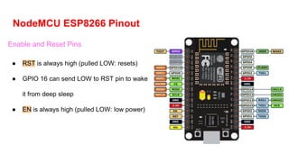
NodeMCU ESP8266 Pinout
Enableand Reset Pins
● RST is always high (pulled LOW: resets)
● GPIO 16 can send LOW to RST pin to wake
it from deep sleep
● EN is always high (pulled LOW: low power)
49.
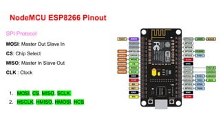
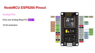
NodeMCU ESP8266 Pinout
SPIProtocol
MOSI: Master Out Slave In
CS: Chip Select
MISO: Master In Slave Out
CLK : Clock
1. MOSI, CS, MISO, SCLK
2. HSCLK, HMISO, HMOSI, HCS
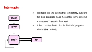
Interrupts
● Interrupts arethe events that temporarily suspend
the main program, pass the control to the external
sources and execute their task.
● It then passes the control to the main program
where it had left off.
56.
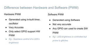
Difference between Hardwareand Software (PWM)
Software PWM
● Generated using Software
● Not very accurate
● Any GPIO can used to create SW
PWM
● Eg:- LED brightness is controlled but
prone to glitches
Hardware PWM
● Generated using in-built timer,
oscillator
● Very Accurate
● Only select GPIO support HW
PWM
● Eg:- Seamless control of a LED’s
brightness
57.
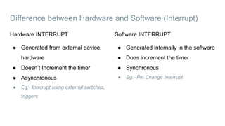
Difference between Hardwareand Software (Interrupt)
Software INTERRUPT
● Generated internally in the software
● Does increment the timer
● Synchronous
● Eg:- Pin Change Interrupt
Hardware INTERRUPT
● Generated from external device,
hardware
● Doesn’t Increment the timer
● Asynchronous
● Eg:- Interrupt using external switches,
triggers
WiFi facilities onNodeMCU
● Can act both as a Wifi Station and Wifi
Access Point
● Can send and receive data from
websites/internet
● Can be used to connect different MCU
● Can be used for automation purposes
● Add #include <ESP8266WiFi.h> at the top
● Add Wifi.softAP(); line in void setup to
connect external devices to esp8266
● Add Wifi.begin(); line in void setup to
connect to esp8266 a modem