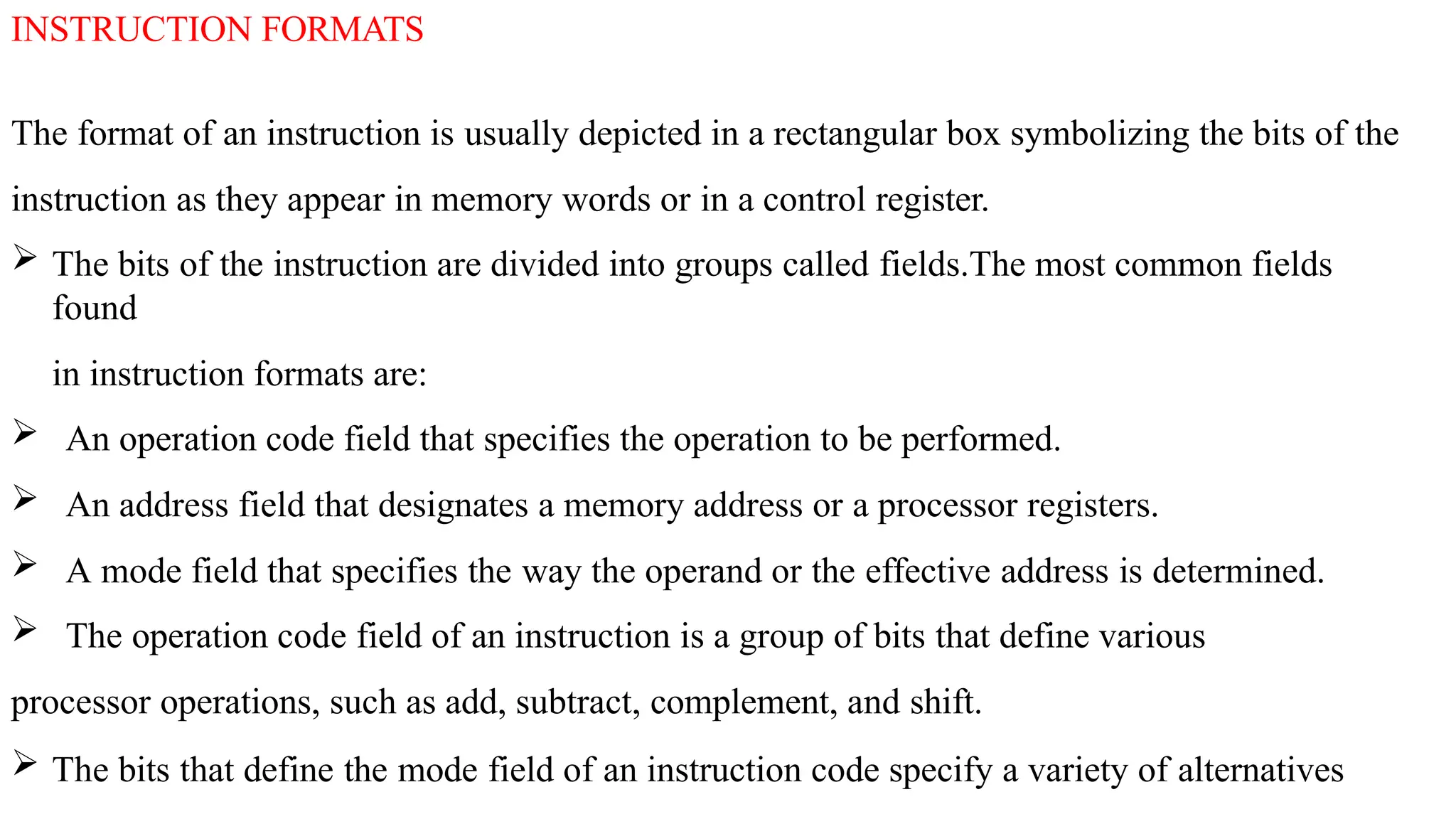
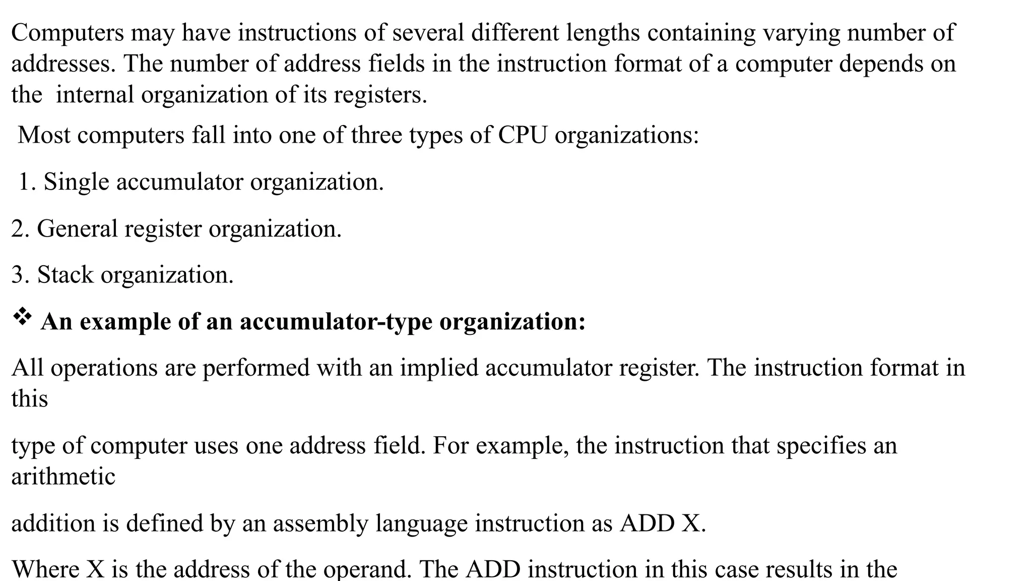
The document explains various instruction formats in computer systems, detailing the organization of fields such as the operation code, address, and mode fields. It describes different CPU organizations including single accumulator, general register, and stack organizations, explaining how they affect the structure of instruction formats. Additionally, it illustrates the use of zero, one, two, and three-address instructions in evaluating arithmetic expressions with specific assembly language examples.

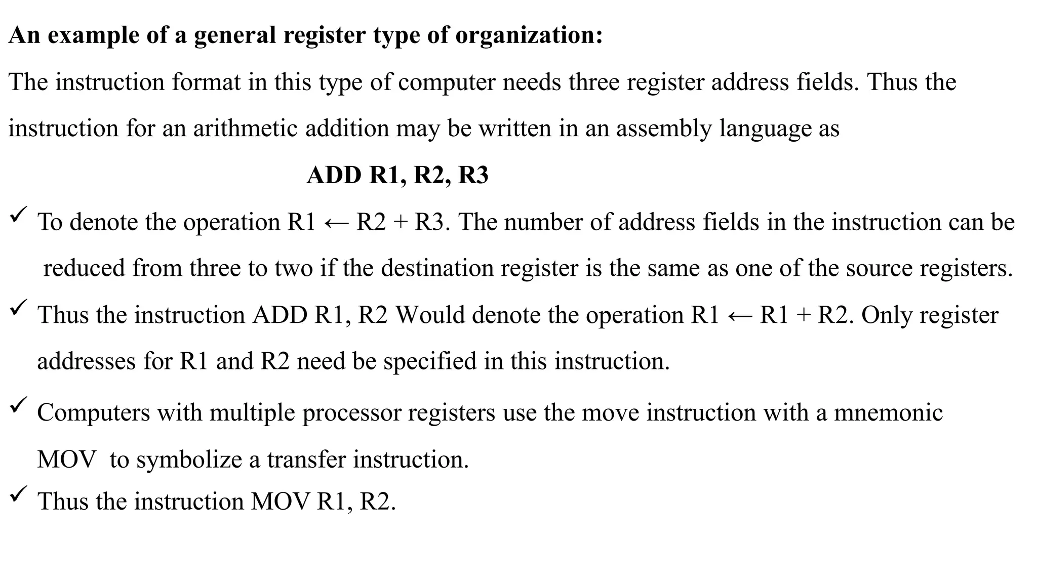
![ Denotes the transfer R1 ← R2 (or R2 ← R1, depending on the particular computer).
Thus transfer-type instructions need two address fields to specify the source and the
destination.
General register-type computers employ two or three address fields in their instruction format.
Each address field may specify a processor register or a memory word.
An instruction symbolized by ADD R1, X Would specify the operation R1 ← R1 + M [X]. It
has two address fields, one for register R1 and the other for the memory address X.
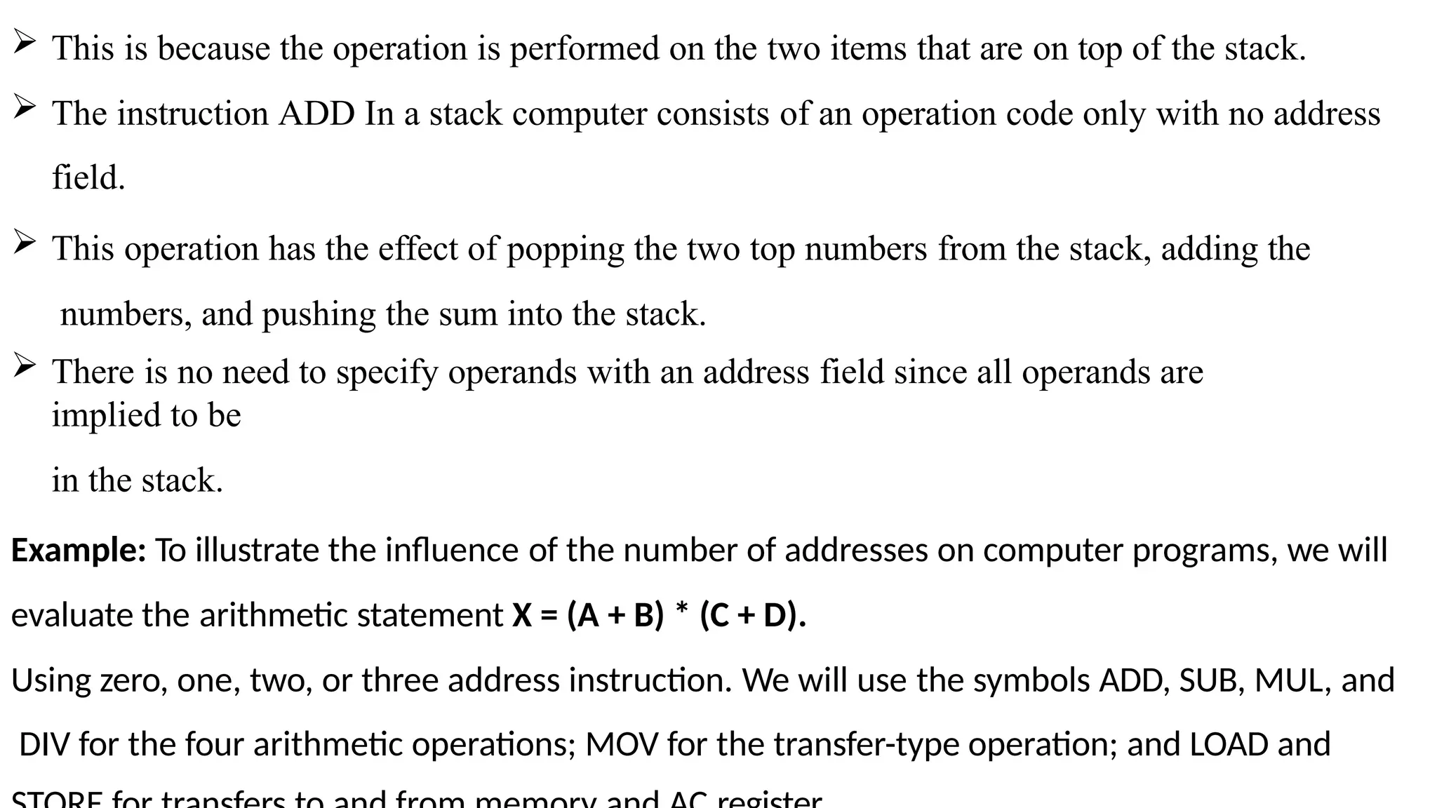
The stack-organized: The Computers with stack organization would have PUSH and POP
instructions which require an address field. Thus the instruction PUSH X Will push the word at
address X to the top of the stack.
The stack pointer is updated automatically. Operation-type instructions do not need an
address](https://image.slidesharecdn.com/coaaa-241206171326-96896882/75/instruction-format-in-computer-organisation-pptx-5-2048.jpg)
![We will assume that the operands are in memory addresses A, B, C, and D, and the result must
be stored in memory at address X.
Three-Address Instructions: Computers with three-address instruction formats can use each
address field to specify either a processor register or a memory operand. The program in
assembly language that evaluates X = (A + B) * (C + D) is shown below, together with
comments that
explain the register transfer operation of each instruction.
ADD R1, A, B
ADD R2, C, D
MUL X, R1, R2
R1 ← M [A] + M [B]
R2 ← M [C] + M [D]
M [X] ← R1 * R2
It is assumed that the computer has two processor registers, R1 and R2. The symbol M
[A]
denotes the operand at memory address symbolized by A.](https://image.slidesharecdn.com/coaaa-241206171326-96896882/75/instruction-format-in-computer-organisation-pptx-7-2048.jpg)
![The advantage of the three-address format is that it results in short programs when evaluating
arithmetic expressions. The disadvantage is that the binary-coded instructions require too
many bits to specify three addresses.
Two-Address Instructions: Two address instructions are the most common in commercial
computers. Here again each address field can specify either a processor register or a
memory word. The program to evaluate X = (A + B) * (C + D) is as follows:
MOV R1, A R1 ← M [A]
ADD R1, B R1 ← R1 + M [B]
MOV R2, C R2 ← M [C]
ADD R2, D R2 ← R2 + M [D]
MUL R1, R2 R1 ← R1*R2
MOV X, R1 M [X] ← R1](https://image.slidesharecdn.com/coaaa-241206171326-96896882/75/instruction-format-in-computer-organisation-pptx-8-2048.jpg)
![ The MOV instruction moves or transfers the operands to and from memory and processor
registers. The first symbol listed in an instruction is assumed to be both a source and the
destination where the result of the operation is transferred.
One-Address Instructions:One-address instructions use an implied accumulator (AC) register
for all data manipulation. For multiplication and division there is a need for a second register.
However, here we will neglect the second register and assume that the AC contains the result
of
all operations. The program to evaluate X = (A + B) * (C + D) is
LOAD A
ADD B
STORE T
LOAD C
ADD D
AC ← M [A]
AC ← A [C] + M
[B] M [T] ← AC
AC ← M [C]
AC ← AC + M [D]](https://image.slidesharecdn.com/coaaa-241206171326-96896882/75/instruction-format-in-computer-organisation-pptx-9-2048.jpg)
![MUL T
STORE X
AC ← AC * M
[T]
M [X] ← AC
All operations are done between the AC register and a memory operand. T is the address of
a temporary memory location required for storing the intermediate result.
Zero-Address Instructions:A stack-organized computer does not use an address field for the
instructions ADD and MUL. The PUSH and POP instructions, however, need an address field
to specify the operand that communicates with the stack.
The following program shows how X = (A + B) ∗ (C + D) will be written for a stack
organized computer. (TOS stands for top of stack)
PUSH A
PUSH
B ADD
TOS ← A
TOS ←
B](https://image.slidesharecdn.com/coaaa-241206171326-96896882/75/instruction-format-in-computer-organisation-pptx-10-2048.jpg)
![PUSH C
PUSH
D ADD
MUL
POP X
TOS ← C
TOS ←
D
TOS ←
(C + D)
TOS ← (C + D) * (A +
B) M [X] ← TOS
To evaluate arithmetic expressions in a stack computer, it is necessary to convert the expression
into reverse Polish notation.
The name “zero-address” is given to this type of computer because of the absence of an
address
field in the computational instructions.](https://image.slidesharecdn.com/coaaa-241206171326-96896882/75/instruction-format-in-computer-organisation-pptx-11-2048.jpg)