![CPU Organization
i. Single accumulator organization:
Example:
1/12/2023 Department of CSE (AI/ML) 8
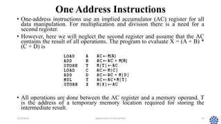
• For example, the instruction that specifies an arithmetic addition is
defined by an assembly language instruction as ADD X where X is
the address of the operand.
The ADD instruction in this case results in the operation AC AC
+ M[X].
AC is the accumulator register and M[X] symbolizes the memory
word located at address X.](https://image.slidesharecdn.com/session12instructionformat-230116144350-f697336c/85/CS304PC-Computer-Organization-and-Architecture-Session-12-Instruction-Format-pptx-8-320.jpg)
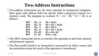
![Three-Address Instructions
1/12/2023 Department of CSE (AI/ML) 11
• Computers with three-address instruction formats can use each address field
to specify either a processor register or a memory operand.
• The program in assembly language that evaluates X = (A + B) * (C + D) is
shown below, together with comments that explain the register transfer
operation of each instruction.
• It is assumed that the computer has two processor registers, R1 and R2. The
symbol M[A] denotes the operand at memory address symbolized by A.
• The advantage of the three-address format is that it results in short programs
when evaluating arithmetic expressions.
• The disadvantage is that the binary-coded instructions require too many bits
to specify three addresses.](https://image.slidesharecdn.com/session12instructionformat-230116144350-f697336c/85/CS304PC-Computer-Organization-and-Architecture-Session-12-Instruction-Format-pptx-11-320.jpg)


This document summarizes the topics covered in Session 12 of the CS304PC course on Computer Organization and Architecture. It discusses different CPU organizations including single accumulator, general register, and stack organizations. It also describes instruction formats, addressing modes, and the influence of the number of instruction addresses. Specific topics covered include general register organization, instruction formats, addressing modes, data transfer and manipulation, and program control. Examples are provided to illustrate zero-address, one-address, two-address, and three-address instruction formats.