The paper discusses an integrated INS/GPS navigation system for hypersonic UAVs to enhance precision and reliability by overcoming the limitations of using INS and GPS independently. A Kalman filter is employed to estimate and correct navigation errors, improving overall accuracy and anti-interference capabilities. Simulations indicate that this integrated approach meets the navigation accuracy requirements for high-speed and dynamic environments of hypersonic vehicles.
![TELKOMNIKA Indonesian Journal of Electrical Engineering
Vol.12, No.1, January 2014, pp. 398 ~ 405
DOI: http://dx.doi.org/10.11591/telkomnika.v12i1.4143 398
Received June 26, 2013; Revised August 27, 2013; Accepted September 19, 2013
INS/GPS Integrated Navigation Technology for
Hypersonic UAV
Wenya Zhou, Hongtu Ma, Shunan Wu*, Nana Meng
School of Aeronautics and Astronautics, Dalian University of Technology
No.2 Linggong Road, Dalian, 116023, Liaoning, China
*Corresponding author, email: laomax@mail.dlut.edu.cn
Abstract
INS/GPS integrated navigation system is studied in this paper for the hypersonic UAV in order to
satisfy the precise guidance requirements of hypersonic UAV and in response to the defects while the
inertial navigation system (INS) and the global positioning system (GPS) are being applied separately. The
information of UAV including position, velocity and attitude can be obtained by using INS and GPS
respectively after generating a reference trajectory. The corresponding errors of two navigation systems
can be obtained through comparing the navigation information of the above two guidance systems.
Kalman filter is designed to estimate the navigation errors and then the navigation information of INS are
corrected. The non-equivalence relationship between the platform misalignment angle and attitude error
angle are considered so that the navigation accuracy is further improved. The Simulink simulation results
show that INS/GPS integrated navigation system can help to achieve higher accuracy and better anti-
interference ability than INS navigation system and this system can also satisfy the navigation accuracy
requirements of hypersonic UAV.
Keywords: hypersonic UAV, INS/GPS integrated navigation, Kalman filter
Copyright © 2014 Institute of Advanced Engineering and Science. All rights reserved.
1. Introduction
Hypersonic vehicle has become the commanding heights of current military competition
with its advantages of rapid global reach and high penetration probability. Because hypersonic
vehicle will operate at the high velocity and with high dynamics, the navigation system of
hypersonic vehicle is the critical factor to ensure the completion of precise strike missions.
The INS can obtain all navigation information at high accuracy independently within
short period of time. However, if it works for long time, the error of the INS will be rapidly
accumulated over time and the navigation precision will be decreased [1]. The GPS can obtain
high-accuracy information of velocity and position. However, while the carrier is moving with
high dynamics, it is difficult for GPS receiver to track the satellite carrier signal and GPS
receiver will be out of work due to lock-lose, so it is difficult to guarantee its reliability also [2].
Therefore, in order to effectively solve the problems while using INS or GPS separately and to
guarantee the high reliability and high precision navigation performance of hypersonic UAV
under long time working condition, the best way is to integrate the INS with GPS to INS/GPS
integrated navigation system. Then the optimum digital filter technology can be used to estimate
the navigation error and correct the navigation information output from INS. INS/GPS integrated
navigation system is superior to the individual system in terms of accuracy, performance and
reliability [3,4]. In addition, this combination has the potential to detecting the accumulated error
while the common integrated navigation system is unable to achieve [5]. In this study, the non-
equivalence relationship between platform misalignment angle and attitude error angle is
considered so as to further improve the precision of navigation.
2. Basic Principle of Kalman Filter
The equations of state and observation of one linear system are given as follows:
, 1 1 1 1k k k k k kX X G w (1)
k k k kz H X v (2)](https://image.slidesharecdn.com/47d1533-171212082215/75/INS-GPS-Integrated-Navigation-Technology-for-Hypersonic-UAV-1-2048.jpg)
![ ISSN: 2302-4046 TELKOMNIKA
TELKOMNIKA Vol. 12, No. 1, January 2014: 398 – 405
399
where kX is the state variables at time kt ; kw is the system noise at time kt ; kz is the observed
variable at time kt ; kv is the observed noise at time kt ; , 1k k is the state transition matrix from
time 1kt to time kt ; 1kG is the coefficient matrix for system noise; kH is the measurement
matrix of observed equation; kw and kv are independent zero-mean Gaussian white noise
sequence and kQ and kR are their variances respectively.
The estimated value of kX is expressed as ˆ
kX . According to the principle of Kalman
filter, ˆ
kX can be obtained by the following equation:
The one-step prediction of state variable:
/ 1 , 1 1
ˆ ˆ
k k k k kX X (3)
The one-step prediction mean-square error of state variable:
, 1 1
T T
/ 1 , 1 1 1 1k k kk k k k k k kP P G Q G (4)
The filter gain:
T T 1
/ 1 / 1( )k k k k k k k k kK P H H P H R
(5)
The optimized state estimation:
/ 1 / 1
ˆ ˆ ˆ( )k k k k k k k kX X K z H X (6)
The mean-square error of estimator:
T T
/ 1( ) ( ) kk k k k k k k k kP I K H P I K H K R K (7)
As long as the initial value of 0
ˆX and 0P are given, the state estimation ˆ
kX at time k
can be calculated according to the measured kz at time k .
3. Design of INS/GPS Integrated Navigation System
In this study, firstly INS is used to obtain the position, velocity and attitude information of
hypersonic UAV. Then the corresponding data obtained by GPS is compared with the INS
output data and the difference is used as the inputs for Kalman filter. Kalman filter will output
the navigation error estimate to correct the navigation information output from INS [6]. Figure 1
provides the schematic diagram of INS/GPS integrated navigation system for the hypersonic
UAV.
Figure 1. Schematic diagram of INS/GPS integrated navigation system](https://image.slidesharecdn.com/47d1533-171212082215/75/INS-GPS-Integrated-Navigation-Technology-for-Hypersonic-UAV-2-2048.jpg)
![ISSN: 2302-4046
INS/GPS Integrated Navigation Technology for Hypersonic UAV (Shunan Wu)
400
3.1. Mechanical Arrangement of Earth-Fixed Coordinate System
The task of INS mechanical arrangement is to use the appropriate mathematical model
and measurement to calculate the navigation information. Figure 2 shows the flow chart for
calculating the navigation information of UAV in earth-fixed coordinate system.
Figure 2. Mechanized arrangement in earth-fixed coordinate system
As it can be seen from Figure 2, the calculation of the navigation information is divided
into two steps: At first, the angular velocity measured by the gyroscope (body coordinate system
relative to the inertial coordinate system) is used to minus the angular velocity of the Earth
rotation (earth-fixed coordinate system relative to the inertial coordinate system) so to obtain the
desired angular velocity b
eb (the body coordinate system relative to the earth-fixed coordinate
system). The body coordinate system is corrected to the earth-fixed coordinate system by using
b
eb according to quaternion integral method to fix the coordinate transformation matrix.
Secondly, the measured acceleration b
f in the body coordinate system is converted to
acceleration e
f in the earth-fixed coordinate system through the coordinate transformation, and
then the acceleration of gravity and Coriolis acceleration are compensated thereinto. The
velocity and position of UAV can be obtained after integrating the acceleration. The position
coordinates (latitude , longitude and altitude h ) are used to calculate the matrix L
eR . The
transformation matrix L
bR transformed from body coordinate system to the local level coordinate
system can be obtained by L L e
b e bR R R and then the information of the attitude angle can be
achieved.
3.2. Relationship between Platform Misalignment Angle and Attitude Error Angle
Misalignment angle is considered as the attitude angle error in many studies while using
the Kalman filter to estimate the navigation error [7-9]. However, this approximation will increase
the navigation error due to inaccurate mathematical model [10]. In order to improve the
navigation accuracy, the relationship between platform misalignment angle , ,e n u (subscripts
represent east, north and heaven directions in local coordinate) and attitude error angle
, , is achieved in this paper through analyzing the physical meaning of misalignment
angle and attitude angle error. The transformation matrix among navigation coordinate system
( )n , platform coordinate system ( )L and body coordinate system ( )b is with following
relationship [10]:
L L n
b n bR R R (8)](https://image.slidesharecdn.com/47d1533-171212082215/75/INS-GPS-Integrated-Navigation-Technology-for-Hypersonic-UAV-3-2048.jpg)
![ ISSN: 2302-4046 TELKOMNIKA
TELKOMNIKA Vol. 12, No. 1, January 2014: 398 – 405
401
where L
bR is the measured attitude matrix, L
nR is the platform misalignment angle matrix and n
bR
is the ideal attitude matrix.
' ' '
11 12 13
' ' '
21 22 23
' ' '
31 32 33
L
b
T T T
R T T T
T T T
,
11 12 13
21 22 23
31 32 33
n
b
T T T
R T T T
T T T
The platform misalignment angle can be expressed as follows:
e
n
u
As the platform misalignment angle is very small, the following relationship can be
obtained by omitting high order small quantity [ ]L
nR I .
The attitude angle obtained from the inertial navigation system should be the sum of
ideal attitude angle and attitude angle error, that is:
t
t
t
(9)
where , , are the measured attitude angles of INS, , ,t t t are the ideal attitude angles,
, , are the corresponding attitude angle errors.
The following formula can be obtained from (9)
tan tan
tan tan( )
1 tan tan
t
t
t
(10)
As is very small, make Taylor extension for tan and ignore the high-order terms.
The following formula can be obtained.
2
tan tan (1 tan )t t (11)
According to (8), the following formula can be obtained.
'
12 22 3212
'
22 12 3222
tan tan( ) u n
t
u e
T T TT
T T TT
(12)
Make Taylor extension of above formula by ignoring the high-order terms,
22 22
2
2 32 12 3212 12
2 2
22 22
tan (1 tan ) (1 )t t u n e
T T TT T
T TT T
(13)
Combine (13) with (11) and simplify,
32 22 12 32
2 2 2 2
12 22 12 22
= u n e
T T T T
T T T T
(14)
The following formula can be obtained by similar method.](https://image.slidesharecdn.com/47d1533-171212082215/75/INS-GPS-Integrated-Navigation-Technology-for-Hypersonic-UAV-4-2048.jpg)
![ISSN: 2302-4046
INS/GPS Integrated Navigation Technology for Hypersonic UAV (Shunan Wu)
402
12 22
2 2
32 32
=
1 1
n e
T T
T T
(15)
21 33 23 31 13 31 11 33
2 2 2 2
31 33 31 33
e n
T T T T T T T T
T T T T
(16)
3.3. State Equation of INS/GPS Integrated Navigation System
The navigation system is non-linear system in general and the equations describing the
system are very complicated. Although the error equation of navigation system is non-linear, the
high-order terms about error of the nonlinear equations can be ignored because the error is very
small [6]. Thus the error equation of navigation system can be approximately described by one
linear equation.
Integrated navigation system generally consists of 21 state variables: position errors
, , h , velocity errors , ,e n uV V V , platform misalignment angles , ,e n u ,constant drifts of
gyro 1 2 3, ,d d d , random drifts of gyro 1 2 3, ,b b b , constant zero offsets of accelerometer 1 2 3, ,b b b ,
and random drifts of accelerometer 1 2 3, , . Generally speaking, with laboratory conditions and
field instrument testing, the constant drift of gyro and the constant zero offset of accelerometer
can be obtained and the corresponding observables (angle velocity and acceleration) can be
corrected [13]. Therefore, 15 states besides the constant drift of gyro and the constant zero
offset of accelerometer can be used as variables in our study.
The state equation of integrated navigation system is as follows:
( ) ( ) ( ) ( ) ( )X t F t X t G t w t (17)
where T
1 2 3 1 2 3( ) [ , , , , , , , , , , , , , , ]e n u e n u b b bX t h V V V .
The non-zero elements of ( )F t are (1,3)
R
F
h
,
1
(1,5)
R
F
h
, (2,1) tanF ,
(2,3)
R
F
h
,
1
(2,4)
(R )cos
F
h
, (3,6) 1F , (4,1) 2 ( sin cos )
cos
n
e u n
V
F V V
,
(4,4) tan
R
h
F
h
, (4,5) (2 )sineF , (4,6) (2 )coseF , (4,8) uF f ,
(4,9) nF f , 11(4,13)F R , 12(4,14)F R , 13(4,15)F R , (5,1) 2 cos
cos
e
e e
V
F V
,
(5,4) 2( )sineF , (5,5)
R
h
F
h
, (5,6)F , (5,7) uF f , (5,9) eF f , 21(5,13)F R ,
22(5,14)F R , 23(5,15)F R , (6,1) 2 sine eF V , (6,4) 2( )coseF , (6,5) 2F ,
(6,7) nF f , (6,8) eF f , 31(6,13)F R , 32(6,14)F R , 33(6,15)F R , (7,3)
R
F
h
,
1
(7,5)
R
F
h
, (7,8) ( )sineF , (7,9) ( )coseF , 11(7,10)F R , 12(7,11)F R ,
13(7,12)F R , (8,1) sineF ,
cos
(8,3)
R
F
h
,
1
(8,4)
R
F
h
, (8,7) ( )sineF ,
(8,9)F , 21(8,10)F R , 22(8,11)F R , 23(8,12)F R , (9,1) cos
cos
eF
,
sin
(9,3)
R
F
h
,
tan
(9,4)
R
F
h
, (9,7) ( )coseF , (9,8)F , 31(9,10)F R ,
32(9,11)F R , 33(9,12)F R , where R represents the radius of earth, e represents the
rotational angular velocity of earth.](https://image.slidesharecdn.com/47d1533-171212082215/75/INS-GPS-Integrated-Navigation-Technology-for-Hypersonic-UAV-5-2048.jpg)
![ ISSN: 2302-4046 TELKOMNIKA
TELKOMNIKA Vol. 12, No. 1, January 2014: 398 – 405
403
Format of G is taken as [ (9,6); (6)]G zeros eye .
3.4. Measurement Equation of INS/GPS Integrated Navigation System
The difference of corresponding navigation information (position and speed) between
INS and GPS is considered as the observables of Kalman filter. In this difference, the real
navigation parameters have been offset and the rest are the errors of the two navigation
systems. Therefore, the measurement equation of navigation system is also linear equation.
The measurement equation could be expressed as follows:
( ) ( ) ( )
I G
I G
I G
Ie Ge
In Gn
Iu Gu
h h
z H t X t v t
V V
V V
V V
(18)
where 6 6 6 3 6 60 0H I .
The subscripts I“ ” and G“ ” represent the states of INS and GPS navigation system
respectively.
Thus, the INS mechanical arrangement is completed and the relationship between the
platform misalignment angle and the attitude error angle has been achieved. Moreover, the
state equation and measurement equation of integrated navigation system has been built.
4. Simulation of INS/GPS Integrated Navigation System
In order to verify the feasibility of the above scheme, the simulation platform of the
INS/GPS integrated navigation system is established. The simulation of integrated navigation
system of hypersonic UAV under sliding condition will be given in the later sections. The
simulation conditions are as follows: Kamlan filter calculation cycle is 0.1 seconds, the
simulation time is set to 600 seconds, random drift of gyro is o
1 /h and random drift of
accelerometer is 500μg . Under the above conditions, the simulation has been conducted for
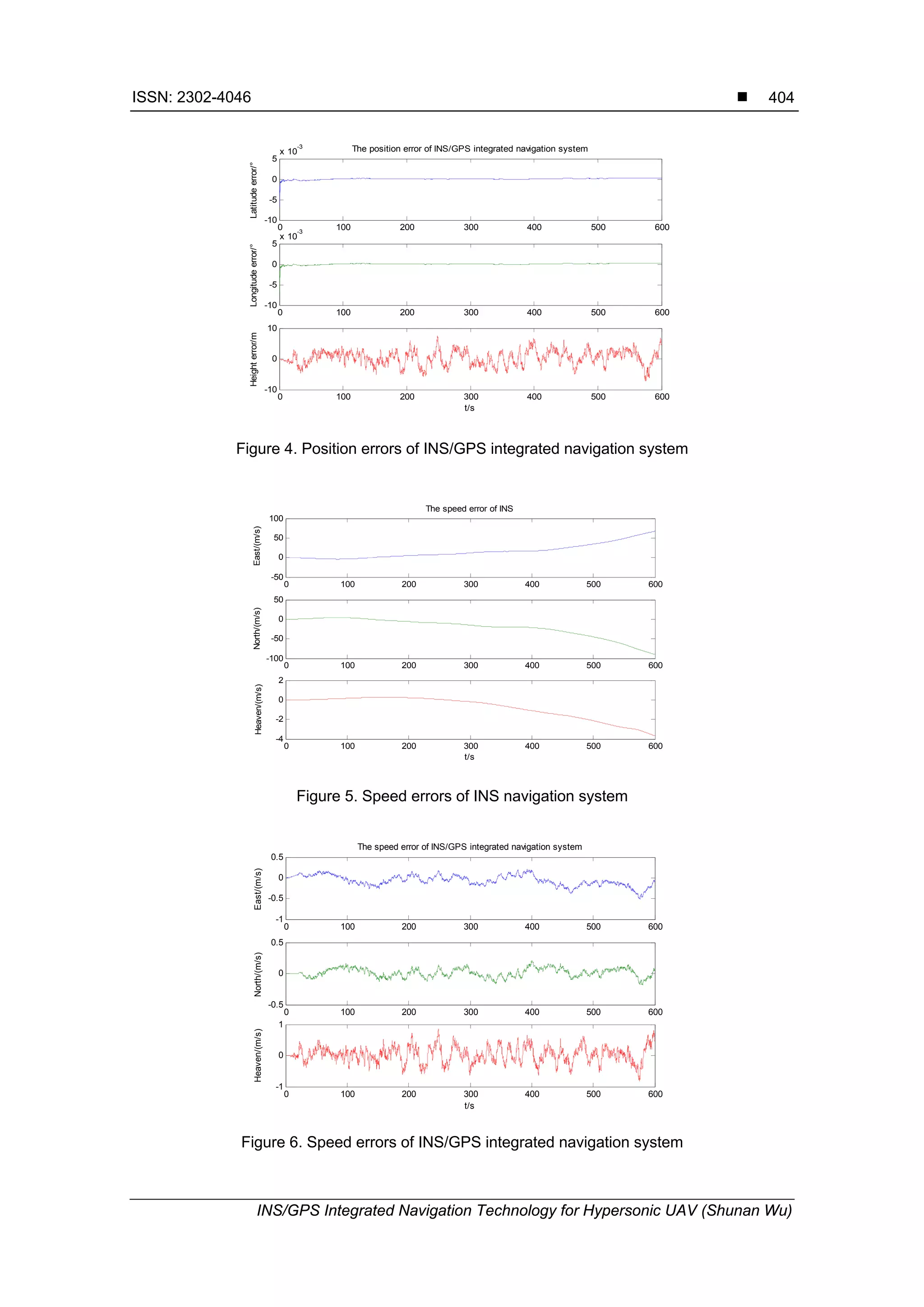
INS and INS/GPS integrated navigation system respectively. Figure 3 and Figure 4 show the
position error of INS and INS/GPS integrated navigation system respectively; Figure 5 and
Figure 6 show the velocity error of INS and INS/GPS integrated navigation system respectively.
Figure 3. Position errors of INS navigation system
0 100 200 300 400 500 600
-0.2
0
0.2
The position error of INS
Latitudeerror/°
0 100 200 300 400 500 600
-0.1
0
0.1
Longitudeerror/°
0 100 200 300 400 500 600
-500
0
500
t/s
Heighterror/m](https://image.slidesharecdn.com/47d1533-171212082215/75/INS-GPS-Integrated-Navigation-Technology-for-Hypersonic-UAV-6-2048.jpg)
![ ISSN: 2302-4046 TELKOMNIKA
TELKOMNIKA Vol. 12, No. 1, January 2014: 398 – 405
405
These figures show that the accumulated error of INS will cause the obvious increasing
of position error and velocity error with the increase of time, so separate application can not
satisfy the navigation requirements. INS/GPS integrated navigation system significantly
improved the navigation accuracy since it is able to output much more accurate information of
position and velocity. Besides, the navigation errors of INS/GPS integrated navigation system
will not be accumulated over time. Therefore, INS/GPS integrated navigation system is a
relatively ideal integrated navigation system which can satisfy the navigation requirements of
hypersonic UAV.
5. Conclusion
INS/GPS integrated navigation system is designed for hypersonic UAV. The integrated
navigation accuracy is further improved through introducing the conversion relationship between
misalignment angle and attitude angle error. Simulation results show that the INS/GPS
integrated navigation system is able to achieve higher level of navigation accuracy than INS and
meanwhile the reliability of system can be improved. The design requirements of navigation
system for hypersonic UAV can be satisfied.
References
[1] Nafees W, Ashraf Z, Akhtar H. Implementation of GPS/INS Integrated Navigation System Using
Loosely Coupled Kalman Filter. 2010 International Conference on Test and Measurement
(ICTM2010). Phuket. 2010; 7: 291-295.
[2] Yuan LQ, Jing ZR. Simulation of Integrated SINS/GPS Navigation System with Kalman Filtering.
Process Automation Instrumentation. 2011; 32(1): 67-68.
[3] Guo HD. Neural Network Aided Kalman Filtering For Integrated GPS/INS Navigation System.
TELKOMNIKA Indonesia Journal of Electrical Engineering. 2013; 11(3): 1221-1226.
[4] Wang YR, Zhang H, Zhou QF. Adaptive Integrated Navigation Filtering Based on Accelerometer
Calibration. TELKOMNIKA Indonesia Journal of Electrical Engineering. 2012; 10(7): 1869-1878.
[5] Bhatti UI, Ochieng WY, Feng SJ. Integrity of an Integrated GPS/INS System in the Presence of
Slowly Growing Errors. GPS Solutions. 2007; 11(3): 173-181.
[6] Qing YY, Zhang HY, Wang SH. Kalman Filter and Integrated Navigation Theory. Xi’an: Northwestern
Polytechnical University Press. 1998.
[7] Mu FX, Ji M, Zhang ZJ. Hypersonic Aircraft Integrated Navigation Algorithm. Aeronautical Computing
Technique. 2010; 40(5): 55-57.
[8] Cheng HB, Zhang HB, Lu H. SINS/GPS Integrated Navigation System for Airborne Missile. Journal of
Projectiles, Rockets, Missiles and Guidance. 2012; 32(5): 14-16.
[9] Li F, Duan ZM, Gong C. Research and Simulation of Integrated SINS/GPS Navigation System.
Electronic Measurement Technology. 2008; 31(3): 7-10.
[10] Guo FS, Yu YF, Qi X. Complete Integrated Algorithm in IMU/GPS/DCM Navigation System.
Computer Measurement and Control. 2008; 16(10): 1485-1488.
[11] Dong XR, Zhang SX, Hua ZC. GPS/INS Integrated Navigation and Its Application. Changsha:
National University of Defense Technology Press. 1998.](https://image.slidesharecdn.com/47d1533-171212082215/75/INS-GPS-Integrated-Navigation-Technology-for-Hypersonic-UAV-8-2048.jpg)