Download as PDF, PPTX


![Smart Battery Switch Demonstrator
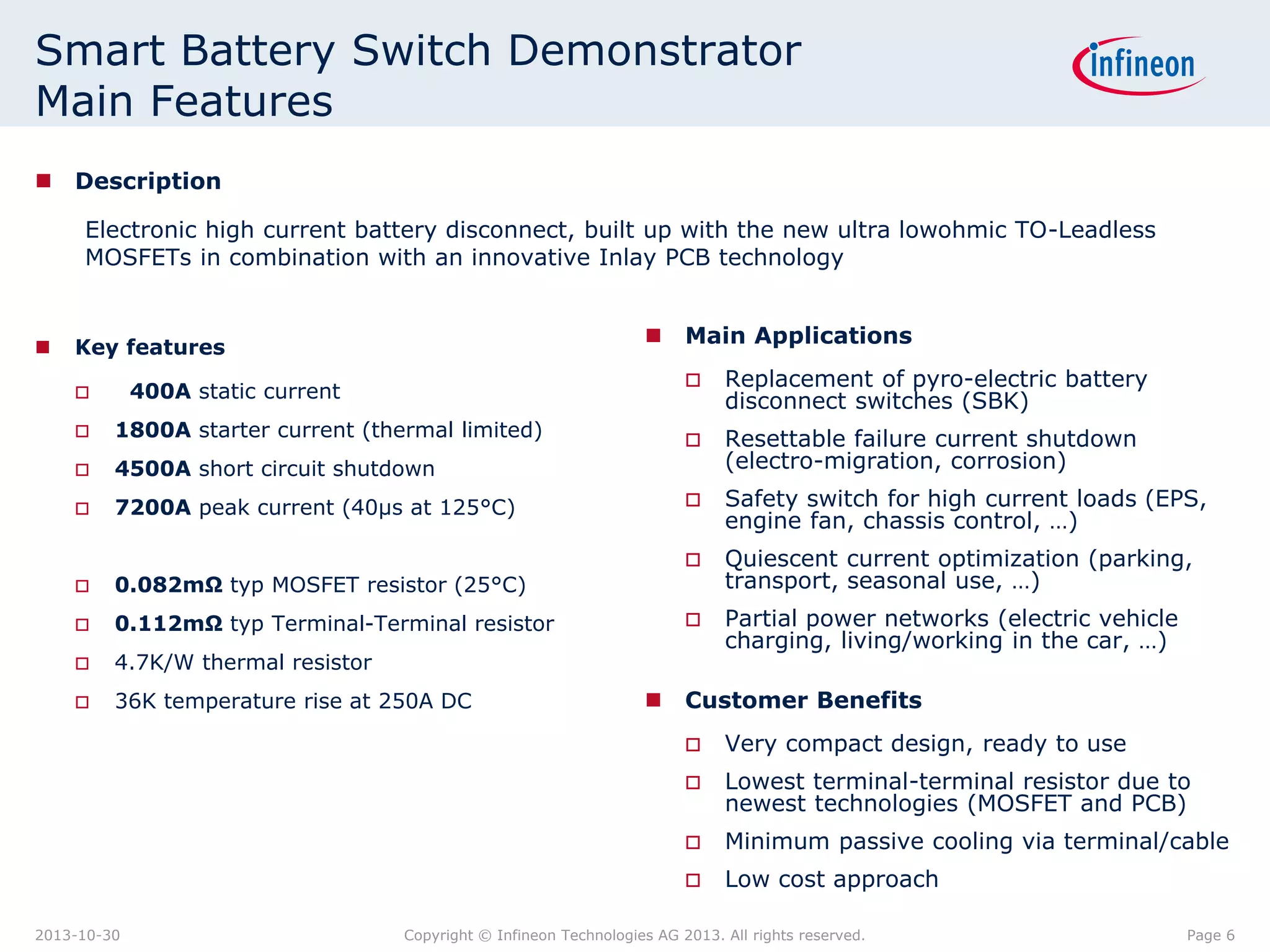
Measurement Results
Description
Measurement results at the Smart Battery Switch, sitting directly on the battery terminal,
50mm² cable at the output, free air convection, ambient temperature is 26°C and the
measurements are done after a thermal settling time of ~30min.
MOSFETs Terminal-to-
Terminal
Current
[A]
Voltage
drop
[mV)
Resistor
[µOhm]
Power
loss
[W]
delta_T
static
junction-
ambient
[K]
Voltage
drop
[mV]
Resistor
[µOhm]
Power
loss
[W]
50 4.1 82 0.2 3.7 5.6 112 0.3
100 8.2 82 0.8 7.4 11.2 112 1.2
250 22.9 92 5.7 36 31.1 124 7.8
400 43.4 108 17.4 80 57.7 144 23.1
Page 72013-10-30 Copyright © Infineon Technologies AG 2013. All rights reserved.](https://image.slidesharecdn.com/infineon-smart-battery-switch-demonstrator-pp-v0100-en-160526101149/75/Infineon-Smart-Battery-Switch-Demonstrator-7-2048.jpg)

![Page 10Copyright © Infineon Technologies 2013. All rights reserved.
TOLL - Infineon’s latest PowerMOS Package
40V TOLL Product Portfolio
Product Name
max RDSon
[mOhm]
ID
[A]
LL/NL
RthJC
[K/W]
Status
IPLU300N04S4-R8 0.77 300 NL 0.35 Released
IPLU300N04S4-1R1 1.1 300 NL 0.8 QS-available
IPLU250N04S4-1R7 1.7 250 NL 0.5 QS-available
2013-10-30](https://image.slidesharecdn.com/infineon-smart-battery-switch-demonstrator-pp-v0100-en-160526101149/75/Infineon-Smart-Battery-Switch-Demonstrator-10-2048.jpg)


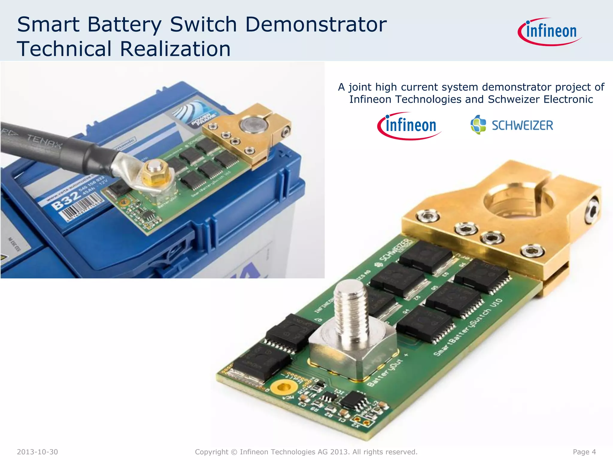
The document describes a smart battery switch demonstrator that uses electronic components rather than a traditional pyroelectric switch. It can handle currents up to 400 amps static and 1800 amps for starting. The demonstrator uses new TO-Leadless MOSFETs combined with a copper inlay PCB technology to achieve low resistances of 0.082mOhm and 0.112mOhm from the MOSFET and terminal to terminal respectively. Measurement results show voltage drops and temperature rises up to different current levels. The technology allows for more flexible control compared to traditional switches and can provide benefits like reduced corrosion.


![Amp 250w mono[1]](https://cdn.slidesharecdn.com/ss_thumbnails/amp250wmono1-121227125036-phpapp01-thumbnail.jpg?width=640&height=640&fit=bounds)


