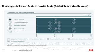
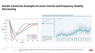
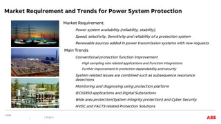
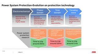
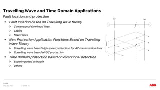
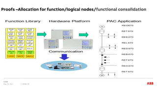
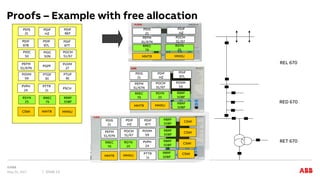
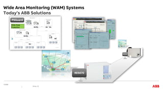
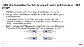
NTNU WORKSHOP, MAY 23RD, 2017
Modern Power System Protection -Trends and Demands
SECRC
Jianping Wang
Contents
• External Power System Changes
• Market Requirement and Main Trends
• Protection Application Trends
• Digital Substations
• Wide Area Protection
• HVDC Protection
| Slide 2
Challenges in Power Grids in Nordic Grids (Added Renewable Sources)
Source: Challenges and Opportunities for the Nordic Power Systems (August, 2016) published by Statnet, Fingrid, Energinet/DK, Svenska
Kraftnet (links: www.svk.se)
Slide 3
Nordic Countries-Example of Lower Inertia and Frequency Quality
Decreasing
Source: Challenges and Opportunities for the Nordic Power Systems (August, 2016) published by Statnet, Fingrid, Energinet/DK, Svenska
Kraftnet
Slide 4
-Sources are located quite far away from the load centers
Long transmission lines are needed
-Multiple Connections from source to the load centers (HVAC+HVDC)
-High Short Circuit Currents reach to the Circuit breaker interruption capability
-Simultaneous commutation failure in HVDC links
-Power system low frequency oscillations
China, India, South Africa, Brazil, etc.
Power System Challenges in Developing Countries
Slide 5
China South Grid-Actions on UHV transmission systems
Typical Example of Long Distance Transmission Systems
CSG total installed capacity=243 GW by end of 2015.
From source side to load side:
500 kV Transmission lines=8, +/- 800/500 kV lines=8, transmission system capacity=35 GW
Slide 6
Source: IEEE Power &Energy Magazine, Volume 14, Nr.4,
P72-78, July/August,2016
Large Disturbance Created in China
2012 “8.8” Accident:
One 500 kV AC Line short circuit
4 HVDC Commutation Failures
Power and Voltage Oscillation occurs
2013 “7.5” Accident:
One 500 kV AC Line short circuit
4 HVDC Commutator Failures
Power and Voltage Oscillation occurs
System impact: 4.53 GW power lost
and restoration needed to use spin reserve to pick up load.
Larger Disturbance Workshop-Records
| Slide 7
Central
China
Grid
East
China
Grid
243 GW
Source: CIGRE 2014 B4 Session in Paris
Generator Damages Due to failure
in protection
Power System Protection Requirement
Speed, Selectivity, Sensitivity, Reliability
Rationale
Application Knowledge
• Power system
dynamics
• Frequency
Control
• Subsynchronous
resonance
• Voltage stability
Power System Stability:
Critical Fault Clearing time
• Fault analysis and
Power System
Transient Calculation
• Speed/Sensitivity
• Reliability
• AC Transmission line
protection
• Generator/Transformer/
Bus protection
• DC Transmission line
protection
• Wide Area Protection
• Distance Protection
• Differential Protection
• Travelling Wave
Proteciton
• Sensitive Fault protection
• Digital Substation Structure and
Communication
• Protection Algorithms
• Phasor/Time domain Signal
Calculation
• Voltage/current transformer
transient
HVDC station
G M
Load
~/= ~/= G
cables
Wind farm



Sin
P
P
dt
d
H
m max
2
2
2



System Blackout related with
protection in US & Canada in
2003/08/14
-273 generator unit tripped
-50 Million peopled affected
| Slide 8
Market Requirement and Trends for Power System Protection
| Slide 9
Market Requirement:
Power system availability (reliability, stability).
Speed, selectivity, Sensitivity and reliability of a protection system
Renewable sources added in power transmission systems with new requests
Main Trends
Conventional protection function improvement
High sampling rate related applications and Function integrations
Further improvement in protection dependability and security
System related issues are combined such as subsequence resonance
detections
Monitoring and diagnosing using protection platform
IEC61850 applications and Digital Substations
Wide area protection(System Integrity protection) and Cyber Security
HVDC and FACTS related Protection Solutions
Power System Protection-Evolution on protection technology
| Slide 10
Electromechanical
Phasor
domain
Time
domain
Traveling
wave
• Reaction time
depends on the
energy
• Highly reliable
• Reaction
depends on
filtering method
• Well developed
technology set
• Reaction time
can be traded
between security
and
dependability
• Reaction
depends on
measurement
equipment time
scale
• Protection
schemes based
measurement of
50/60 Hz
phasors: Vf=V-ZI
• Criteria based on
differential
equation:
• Vf=V-(Ri+L di/dt)
CT/VT improvements+
(hardware Availability)
Travelling Wave Detection
ΔU1,ΔI1, ΔU2,ΔI2
Power system
protection
research
Time to trip
around 20ms
Time to trip
around 10ms
Time to trip
around 5 ms
 Fault location based on Travelling wave theory
 Conventional Overhead lines
 Cables
 Mixed lines
 New Protection Application Functions Based on Travelling
Wave Theory
 Travelling wave based high speed protection for AC transmission lines
 Travelling wave based HVDC protection
 Time domain protection based on directional detection
 Superimposed principle
 Others
Fault location and protection
Travelling Wave and Time Domain Applications
May 22, 2017 Slide 11
Bus 1 Bus 2
F
Time
Proofs –Allocation for function/logical nodes/functional consolidation
May 22, 2017 Slide 12
G
M
RBRF
50BF
RREC
79
MMXU
MMTR
RSYN
25
CSWI
PTUF
81
PTOF
81
PSCH
PTTR
49
POVM
59
PVPH
24
POCM
51/67
PIOC
50N
PUVM
27
RBRF
50BF
PIOC
50
PEFM
51/67N
PDIF
REF
PDIF
HZ
PDIF
87T
PDIF
87L
PDIS
21
PDIF
87B
REG670
RET 670
REB 670
REL 670
RED 670
REB 670
RET 670
RED 670
RET 670
Function Library Hardware Platform PAC Application
Communication
May 22, 2017 Slide 13
Proofs – Example with free allocation
REL 670
RED 670
RET 670
RBRF
50BF
RREC
79
MMXU
MMTR
RSYN
25
CSWI
PTUF
81
PTOF
81
PSCH
PTTR
26
POVM
59
PVPH
24
POCM
51/67
PIOC
50N
PUVM
27
PGPF
PIOC
50
PEFM
51/67N
PDIF
REF
PDIF
HZ
PDIF
87T
PDIF
87L
PDIS
21
PDIF
87B
PDIS
21
PDIF
HZ
POCM
51/67
PEFM
51/67N
RREC
79
RSYN
25
MMTR MMXU
PDIS
21
PDIF
HZ
POCM
51/67
PEFM
51/67N
RREC
79
RSYN
25
MMTR MMXU
PDIF
87L
RBRF
50BF
RBRF
50BF
POVM
59
PDIS
21
PDIF
HZ
POCM
51/67
PEFM
51/67N
RREC
79
RSYN
25
MMTR MMXU
RBRF
50BF
RBRF
50BF
POVM
59
PDIF
87T
RBRF
50BF
RBRF
50BF
CSWI
CSWI
CSWI
CSWI
PVPH
24
PTTR
26
Proofs – Example of Functional consolidation
Reduced footprint, hardware and infrastructure
Comparison of digital vs. traditional solution for static VAr
compensator (SVC) project
 4 ABB Relion relays vs. 14 traditional relays
 50% reduction in number of panels – 4 to 2
Main protection - traditional relays
Kent Wikström
October 11, 2009 | Slide
3

500 kV

23 kV

R

R

R

R

CB
Main protection - digital substation
| Slide 14
Proofs – Example of Functional consolidation
Reduced footprint, hardware and infrastructure
Advanced protection solution
From 3 panels to 1 panel
14 protection & control devices
(Electro-Mechanical system could add 3
devices per function)
2 protection & control devices
including busbar
protection/backup
Conventional Digital
Control
87L
87L
67N
79-2
50
21
21
67N
79-2
50
50
Protection -
subsystems
Control
Control
Control
BBP & CBF
87B, 50BF
P&C 1
P&C 2
| Slide 15
Reduction in panels from 3 to 1
Applications - ABB‘s process bus applications
AIS / GIS Voltage level Current/
voltage
Application Description Status
ABB NCITs with IEC 61850-9-2 merging units
ELK-CP3,
ELK-CP14
GIS 170 – 550kV Current & voltage Protection, control,
revenue metering
Redundant, combined U/I
NCIT,
U: capacitive divider, I:
Rogowski coil
Commercial operation
since 1998. Since 2011
with IEC 61850
FOCS LTB AIS 420kV Current Protection, control Redundant optical CT
integrated in
disconnecting circuit
breaker
Pilot installation since
2010
FOCS FS AIS 72 – 800kV Current Protection, control,
revenue metering
Redundant optical CT, free-
standing
Under development
ABB stand-alone merging units for conventional instrument transformers
SAM600 GIS & AIS any Current & voltage Protection, control,
operational metering
Modular IEC 61850 process
bus I/O system with
modules per primary
object
Ready for pilot
installations
SAM600 GIS & AIS any Current & voltage &
breakers,
disconnectors…
Protection, control,
revenue metering
Modular IEC 61850 process
bus I/O system with
modules per primary
object
Under development
Process level equipment – sensor technology
Slide 16
ABB‘s digital substation product portfolio-Overview
Substation interface and HMI (Station level)
ABB SAS 600 systems
Protection and Contol (Bay level)
Relion family control and protection IEDs
Interface to Switchgear (Process level –
NCIT)
ABB NCITs for GIS, CP-MU merging unit for
ELK-CP14 and ELK-CP3 (current and voltage)
ABB LTB with integrated
Fiber Optic Current Sensor FOCS-MU (current only)
Process level – stand-alone merging units
SAM600 modular process bus IO system
Slide 17
IEC 61850 station bus
IEC 61850 process bus
Remote control
Proofs - ABB’s experience with NCITs and process bus
Some project highlights …..
Pilot installation
Braemar, AU
GIS NCIT,
670series
Pilot installation
Laufenburg, CH
GIS NCIT,
670series, REB500
Pilot installation
Bäsna, SE
FOCS NCIT,
670series
Real installation
Loganlea, AU
GIS NCIT,
670series, REB500
Pilot installation
Bickigen, CH
GIS NCIT,
670series, 3rd party
Real installation
5 more inst., AU
GIS NCIT,
670series, REB500
Pilot installation
Bodelwyd., UK
GIS NCIT,
670 series
Pilot
installation
Nehden, DE
3rd party NCIT,
REB500
2009 2010 2011 2012 2013
Slide 18
Wide Area Monitoring (WAM) Systems
Today’s ABB Solutions
PSGuard
RES521
RES670
Wide Area
Protection
Slide 19
HVDC Line Protection-For Multi-terminal Systems and Embedded HVDC
System
• HVDC transmission will be more and more in the power systems
• Voltage source converter (VSC) based HVDC links shows advantages in
interconnections.
• Protection solution for HVDC lines is naturally required with the
development of HVDC connections, especially for Multi-terminal HVDC
(MTDC) transmission systems.
• Topics related with HVDC protection: Fast Protection, Line Differential
Protection, System Wide Protection, High sensitive protection, etc.
| Slide 20
Industry outlook_ ABB.pdf

Industry outlook_ ABB.pdf

  • 1.
    NTNU WORKSHOP, MAY23RD, 2017 Modern Power System Protection -Trends and Demands SECRC Jianping Wang
  • 2.
    Contents • External PowerSystem Changes • Market Requirement and Main Trends • Protection Application Trends • Digital Substations • Wide Area Protection • HVDC Protection | Slide 2
  • 3.
    Challenges in PowerGrids in Nordic Grids (Added Renewable Sources) Source: Challenges and Opportunities for the Nordic Power Systems (August, 2016) published by Statnet, Fingrid, Energinet/DK, Svenska Kraftnet (links: www.svk.se) Slide 3
  • 4.
    Nordic Countries-Example ofLower Inertia and Frequency Quality Decreasing Source: Challenges and Opportunities for the Nordic Power Systems (August, 2016) published by Statnet, Fingrid, Energinet/DK, Svenska Kraftnet Slide 4
  • 5.
    -Sources are locatedquite far away from the load centers Long transmission lines are needed -Multiple Connections from source to the load centers (HVAC+HVDC) -High Short Circuit Currents reach to the Circuit breaker interruption capability -Simultaneous commutation failure in HVDC links -Power system low frequency oscillations China, India, South Africa, Brazil, etc. Power System Challenges in Developing Countries Slide 5
  • 6.
    China South Grid-Actionson UHV transmission systems Typical Example of Long Distance Transmission Systems CSG total installed capacity=243 GW by end of 2015. From source side to load side: 500 kV Transmission lines=8, +/- 800/500 kV lines=8, transmission system capacity=35 GW Slide 6 Source: IEEE Power &Energy Magazine, Volume 14, Nr.4, P72-78, July/August,2016
  • 7.
    Large Disturbance Createdin China 2012 “8.8” Accident: One 500 kV AC Line short circuit 4 HVDC Commutation Failures Power and Voltage Oscillation occurs 2013 “7.5” Accident: One 500 kV AC Line short circuit 4 HVDC Commutator Failures Power and Voltage Oscillation occurs System impact: 4.53 GW power lost and restoration needed to use spin reserve to pick up load. Larger Disturbance Workshop-Records | Slide 7 Central China Grid East China Grid 243 GW Source: CIGRE 2014 B4 Session in Paris
  • 8.
    Generator Damages Dueto failure in protection Power System Protection Requirement Speed, Selectivity, Sensitivity, Reliability Rationale Application Knowledge • Power system dynamics • Frequency Control • Subsynchronous resonance • Voltage stability Power System Stability: Critical Fault Clearing time • Fault analysis and Power System Transient Calculation • Speed/Sensitivity • Reliability • AC Transmission line protection • Generator/Transformer/ Bus protection • DC Transmission line protection • Wide Area Protection • Distance Protection • Differential Protection • Travelling Wave Proteciton • Sensitive Fault protection • Digital Substation Structure and Communication • Protection Algorithms • Phasor/Time domain Signal Calculation • Voltage/current transformer transient HVDC station G M Load ~/= ~/= G cables Wind farm    Sin P P dt d H m max 2 2 2    System Blackout related with protection in US & Canada in 2003/08/14 -273 generator unit tripped -50 Million peopled affected | Slide 8
  • 9.
    Market Requirement andTrends for Power System Protection | Slide 9 Market Requirement: Power system availability (reliability, stability). Speed, selectivity, Sensitivity and reliability of a protection system Renewable sources added in power transmission systems with new requests Main Trends Conventional protection function improvement High sampling rate related applications and Function integrations Further improvement in protection dependability and security System related issues are combined such as subsequence resonance detections Monitoring and diagnosing using protection platform IEC61850 applications and Digital Substations Wide area protection(System Integrity protection) and Cyber Security HVDC and FACTS related Protection Solutions
  • 10.
    Power System Protection-Evolutionon protection technology | Slide 10 Electromechanical Phasor domain Time domain Traveling wave • Reaction time depends on the energy • Highly reliable • Reaction depends on filtering method • Well developed technology set • Reaction time can be traded between security and dependability • Reaction depends on measurement equipment time scale • Protection schemes based measurement of 50/60 Hz phasors: Vf=V-ZI • Criteria based on differential equation: • Vf=V-(Ri+L di/dt) CT/VT improvements+ (hardware Availability) Travelling Wave Detection ΔU1,ΔI1, ΔU2,ΔI2 Power system protection research Time to trip around 20ms Time to trip around 10ms Time to trip around 5 ms
  • 11.
     Fault locationbased on Travelling wave theory  Conventional Overhead lines  Cables  Mixed lines  New Protection Application Functions Based on Travelling Wave Theory  Travelling wave based high speed protection for AC transmission lines  Travelling wave based HVDC protection  Time domain protection based on directional detection  Superimposed principle  Others Fault location and protection Travelling Wave and Time Domain Applications May 22, 2017 Slide 11 Bus 1 Bus 2 F Time
  • 12.
    Proofs –Allocation forfunction/logical nodes/functional consolidation May 22, 2017 Slide 12 G M RBRF 50BF RREC 79 MMXU MMTR RSYN 25 CSWI PTUF 81 PTOF 81 PSCH PTTR 49 POVM 59 PVPH 24 POCM 51/67 PIOC 50N PUVM 27 RBRF 50BF PIOC 50 PEFM 51/67N PDIF REF PDIF HZ PDIF 87T PDIF 87L PDIS 21 PDIF 87B REG670 RET 670 REB 670 REL 670 RED 670 REB 670 RET 670 RED 670 RET 670 Function Library Hardware Platform PAC Application Communication
  • 13.
    May 22, 2017Slide 13 Proofs – Example with free allocation REL 670 RED 670 RET 670 RBRF 50BF RREC 79 MMXU MMTR RSYN 25 CSWI PTUF 81 PTOF 81 PSCH PTTR 26 POVM 59 PVPH 24 POCM 51/67 PIOC 50N PUVM 27 PGPF PIOC 50 PEFM 51/67N PDIF REF PDIF HZ PDIF 87T PDIF 87L PDIS 21 PDIF 87B PDIS 21 PDIF HZ POCM 51/67 PEFM 51/67N RREC 79 RSYN 25 MMTR MMXU PDIS 21 PDIF HZ POCM 51/67 PEFM 51/67N RREC 79 RSYN 25 MMTR MMXU PDIF 87L RBRF 50BF RBRF 50BF POVM 59 PDIS 21 PDIF HZ POCM 51/67 PEFM 51/67N RREC 79 RSYN 25 MMTR MMXU RBRF 50BF RBRF 50BF POVM 59 PDIF 87T RBRF 50BF RBRF 50BF CSWI CSWI CSWI CSWI PVPH 24 PTTR 26
  • 14.
    Proofs – Exampleof Functional consolidation Reduced footprint, hardware and infrastructure Comparison of digital vs. traditional solution for static VAr compensator (SVC) project  4 ABB Relion relays vs. 14 traditional relays  50% reduction in number of panels – 4 to 2 Main protection - traditional relays Kent Wikström October 11, 2009 | Slide 3  500 kV  23 kV  R  R  R  R  CB Main protection - digital substation | Slide 14
  • 15.
    Proofs – Exampleof Functional consolidation Reduced footprint, hardware and infrastructure Advanced protection solution From 3 panels to 1 panel 14 protection & control devices (Electro-Mechanical system could add 3 devices per function) 2 protection & control devices including busbar protection/backup Conventional Digital Control 87L 87L 67N 79-2 50 21 21 67N 79-2 50 50 Protection - subsystems Control Control Control BBP & CBF 87B, 50BF P&C 1 P&C 2 | Slide 15 Reduction in panels from 3 to 1
  • 16.
    Applications - ABB‘sprocess bus applications AIS / GIS Voltage level Current/ voltage Application Description Status ABB NCITs with IEC 61850-9-2 merging units ELK-CP3, ELK-CP14 GIS 170 – 550kV Current & voltage Protection, control, revenue metering Redundant, combined U/I NCIT, U: capacitive divider, I: Rogowski coil Commercial operation since 1998. Since 2011 with IEC 61850 FOCS LTB AIS 420kV Current Protection, control Redundant optical CT integrated in disconnecting circuit breaker Pilot installation since 2010 FOCS FS AIS 72 – 800kV Current Protection, control, revenue metering Redundant optical CT, free- standing Under development ABB stand-alone merging units for conventional instrument transformers SAM600 GIS & AIS any Current & voltage Protection, control, operational metering Modular IEC 61850 process bus I/O system with modules per primary object Ready for pilot installations SAM600 GIS & AIS any Current & voltage & breakers, disconnectors… Protection, control, revenue metering Modular IEC 61850 process bus I/O system with modules per primary object Under development Process level equipment – sensor technology Slide 16
  • 17.
    ABB‘s digital substationproduct portfolio-Overview Substation interface and HMI (Station level) ABB SAS 600 systems Protection and Contol (Bay level) Relion family control and protection IEDs Interface to Switchgear (Process level – NCIT) ABB NCITs for GIS, CP-MU merging unit for ELK-CP14 and ELK-CP3 (current and voltage) ABB LTB with integrated Fiber Optic Current Sensor FOCS-MU (current only) Process level – stand-alone merging units SAM600 modular process bus IO system Slide 17 IEC 61850 station bus IEC 61850 process bus Remote control
  • 18.
    Proofs - ABB’sexperience with NCITs and process bus Some project highlights ….. Pilot installation Braemar, AU GIS NCIT, 670series Pilot installation Laufenburg, CH GIS NCIT, 670series, REB500 Pilot installation Bäsna, SE FOCS NCIT, 670series Real installation Loganlea, AU GIS NCIT, 670series, REB500 Pilot installation Bickigen, CH GIS NCIT, 670series, 3rd party Real installation 5 more inst., AU GIS NCIT, 670series, REB500 Pilot installation Bodelwyd., UK GIS NCIT, 670 series Pilot installation Nehden, DE 3rd party NCIT, REB500 2009 2010 2011 2012 2013 Slide 18
  • 19.
    Wide Area Monitoring(WAM) Systems Today’s ABB Solutions PSGuard RES521 RES670 Wide Area Protection Slide 19
  • 20.
    HVDC Line Protection-ForMulti-terminal Systems and Embedded HVDC System • HVDC transmission will be more and more in the power systems • Voltage source converter (VSC) based HVDC links shows advantages in interconnections. • Protection solution for HVDC lines is naturally required with the development of HVDC connections, especially for Multi-terminal HVDC (MTDC) transmission systems. • Topics related with HVDC protection: Fast Protection, Line Differential Protection, System Wide Protection, High sensitive protection, etc. | Slide 20