This document provides an overview of industrial automation and process control systems, including basic control concepts, advanced control systems, and the objectives of automation. It describes common automation system types like PLCs, DCSs, and PC-based control systems. It also outlines the architectures of traditional PLCs, DCSs, and industrial PC-based control systems. Finally, it discusses Teclever's PC-based control system offerings, including features like a real-time Linux environment, standard driver support, and SCADA integration. It provides an example case study of a test facility control system project.

![Process Control
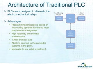
Basic Process Control Concept
A measurement of the state or condition of a process
A controller calculating an action based on this measured value against
a pre-set value [set point]
An output signal resulting from the controller calculation which is used
to manipulate the process action through some form of actuators.
The process itself reacting to this signal, and changing its state or
condition.](https://image.slidesharecdn.com/rtpacsystems-130823005646-phpapp02/85/Industrial-Automation-rtPAC-System-2-320.jpg)
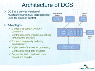
![Advanced Control Systems
Objective: Process control
information system Automating
the Plant Operations
In producing the required output
of the product with minimal
quality variation
Optimal consumption of raw
material and energy
Maximum efficiency
Improved Productivity
Efficient Monitoring and Control
Scalable and Robust
Types of Automation Systems
Programmable Logic
Controller [PLC],
Distributed Control System
[DCS] and
PC Based Control System
Sensors &
SCU
Control
Valve
Control
Station
PLC [or]
DCS [or]
PC Based
ADC
DAC
AA
Process
Controlled VariableMeasured Variable](https://image.slidesharecdn.com/rtpacsystems-130823005646-phpapp02/85/Industrial-Automation-rtPAC-System-3-320.jpg)
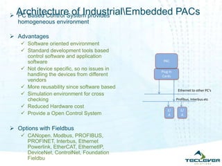
![TECLEVER’s offerings
PC Based Control System Framework
Features
X86 Based system with Medium to High processing power based on
requirement
Real time Linux based environment for Hard Real time application
Developed mostly with FOSS components
Easy integration with any OPC based SCADA packages
Custom Web based control for non critical process monitoring
Standardized driver modules for various Data acquisition cards. [Possible
to have different vendor cPCI/PXI cards]
Possible to have both Data acquisition and control in a single controller.
Possible to configure a High reliable redundant system
Standard Software oriented environment for SCADA and User control
program
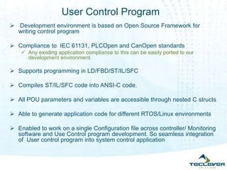
Developed a User Control program framework where support for traditional
Ladder or FBD based development is enabled](https://image.slidesharecdn.com/rtpacsystems-130823005646-phpapp02/85/Industrial-Automation-rtPAC-System-7-320.jpg)
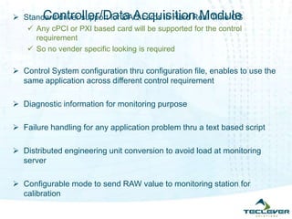
![Controller/Data Acquisition Module
Optional redundancy management for any single point of failure
Possible to have multiple thread User control program
Standard ethernet based communication to and from DAQ system and
server.
High speed operational cycle [Possible to have as small as 10msec]
Able to handle very large number of channel systems](https://image.slidesharecdn.com/rtpacsystems-130823005646-phpapp02/85/Industrial-Automation-rtPAC-System-10-320.jpg)