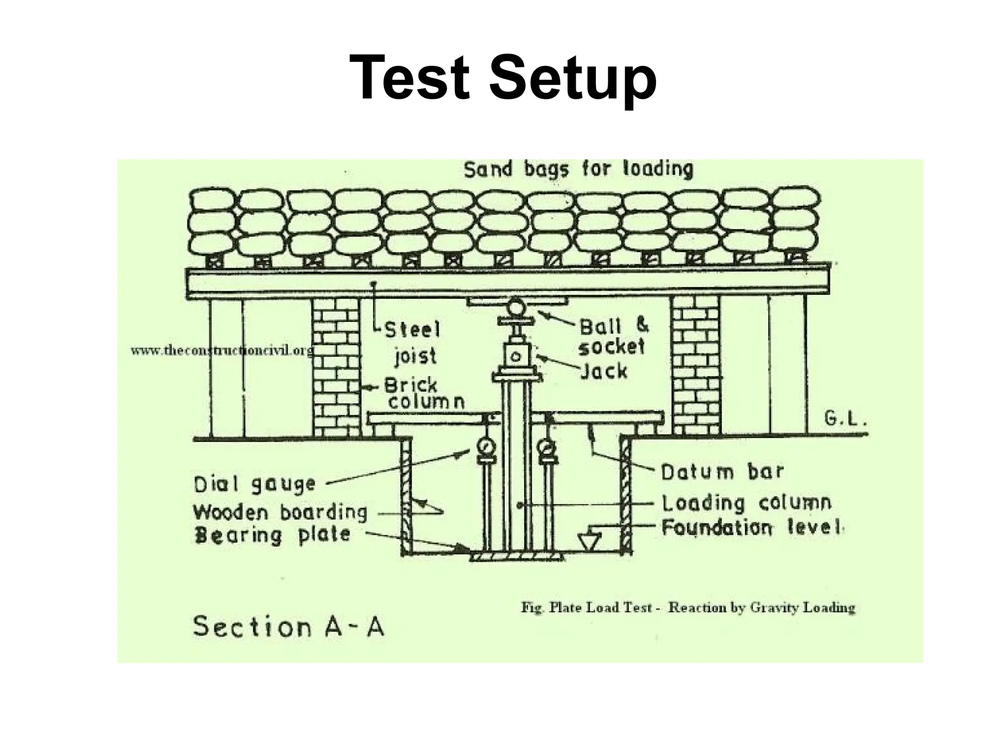
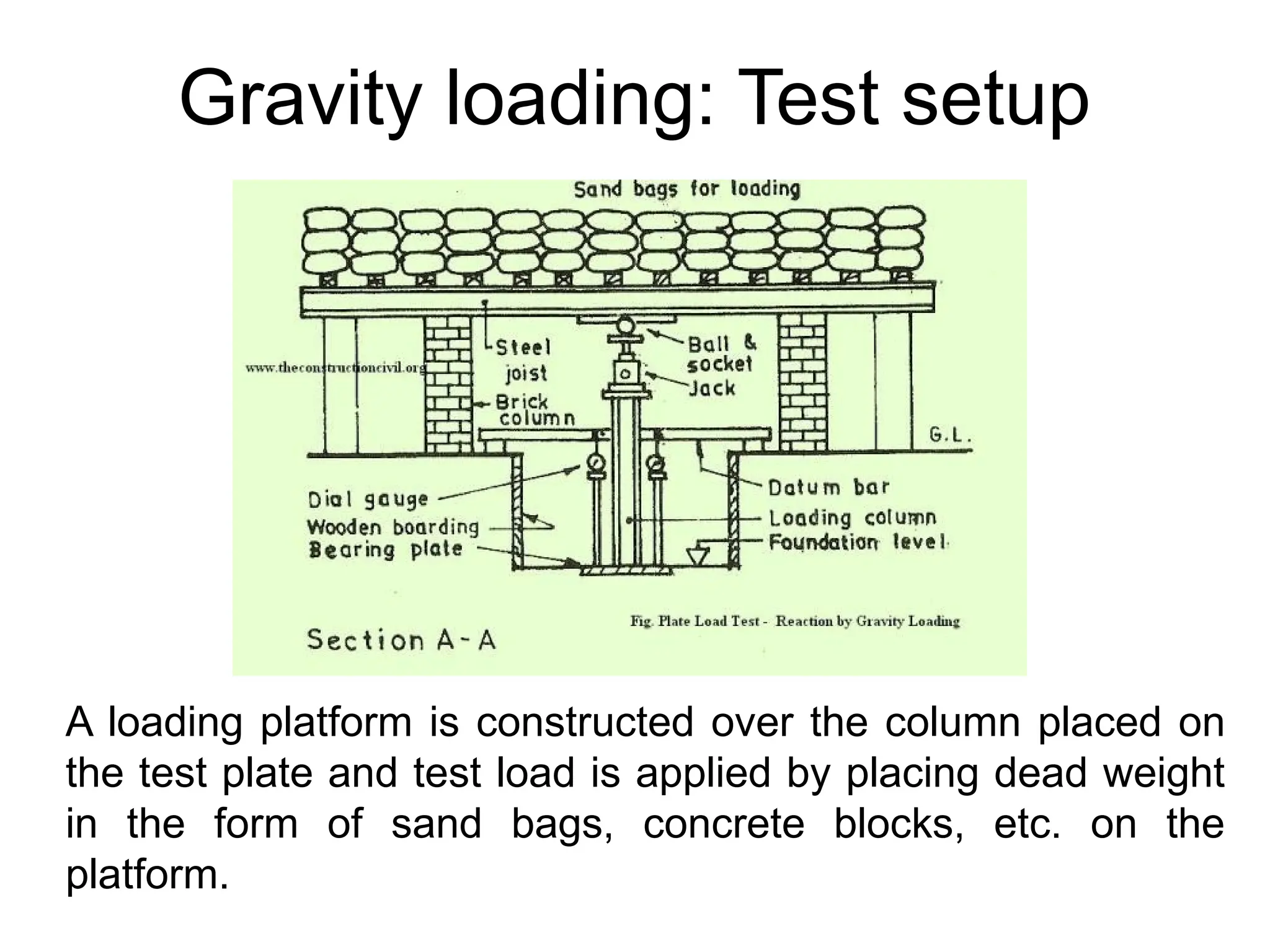
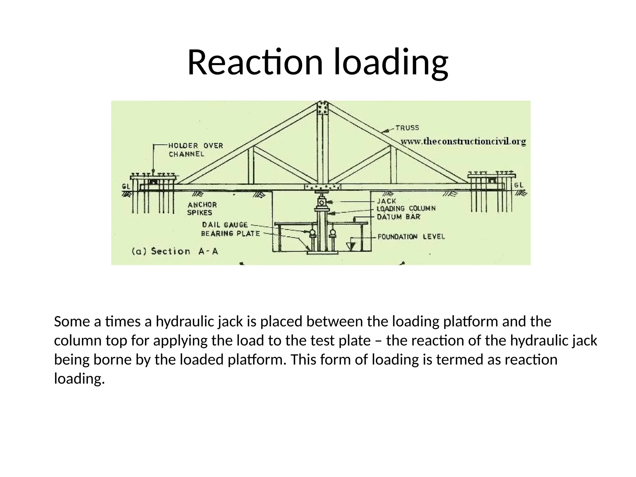
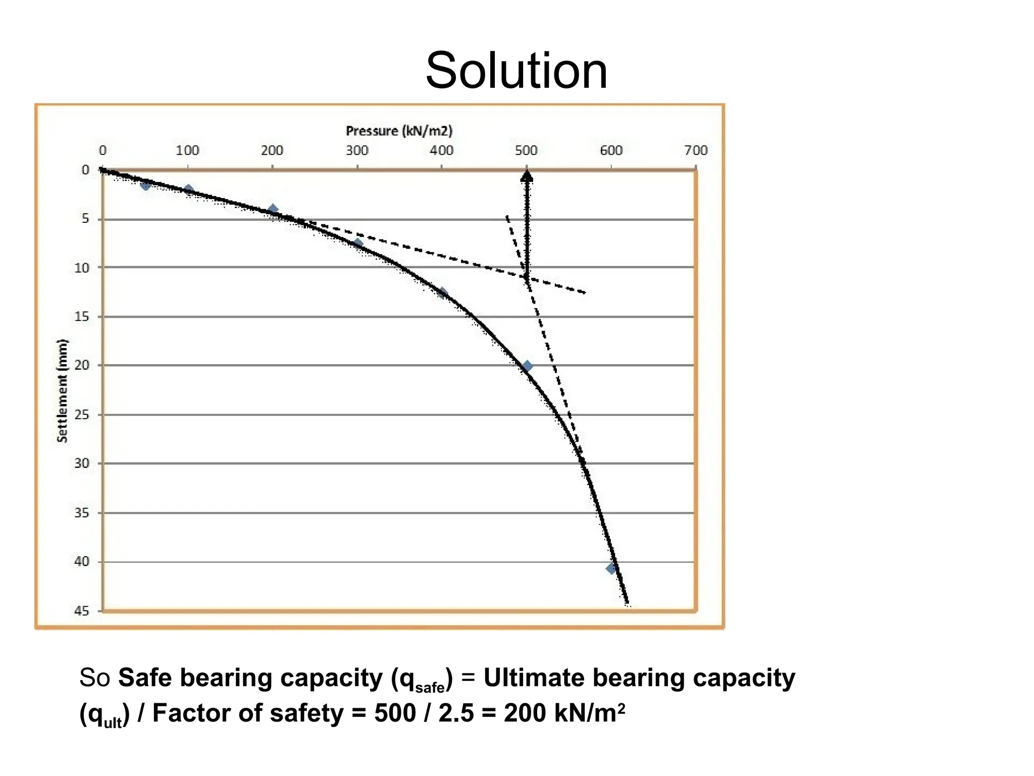
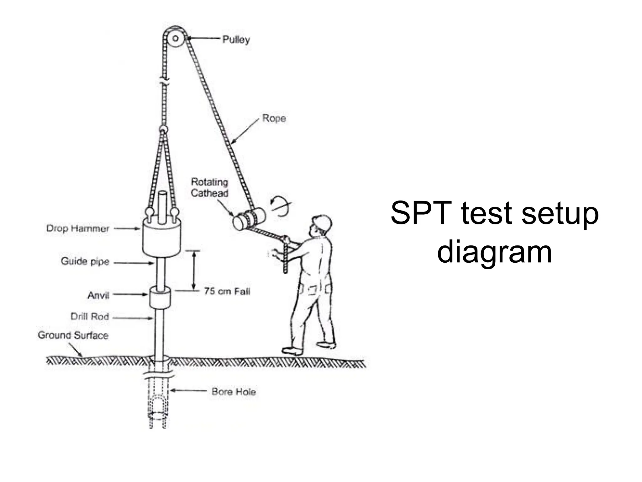
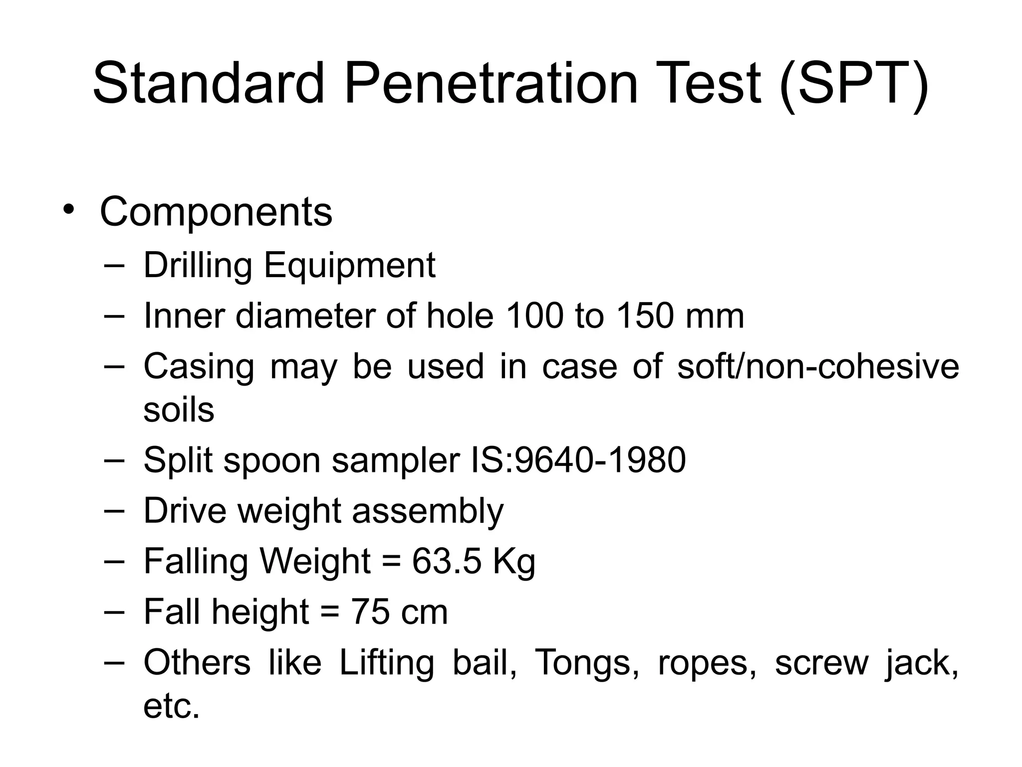
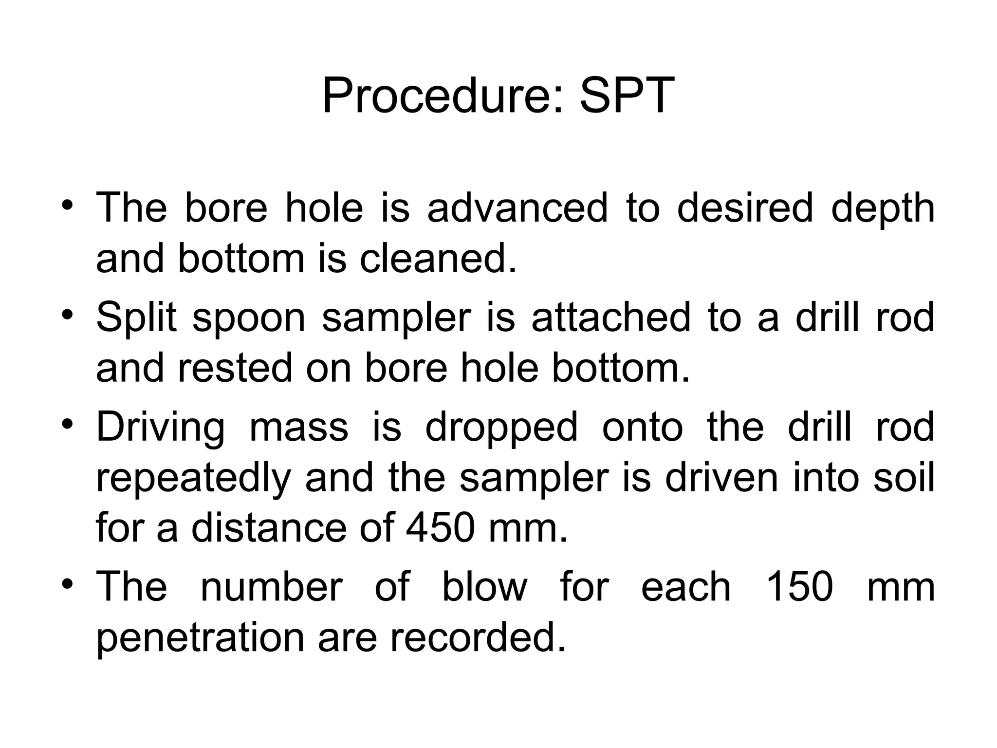
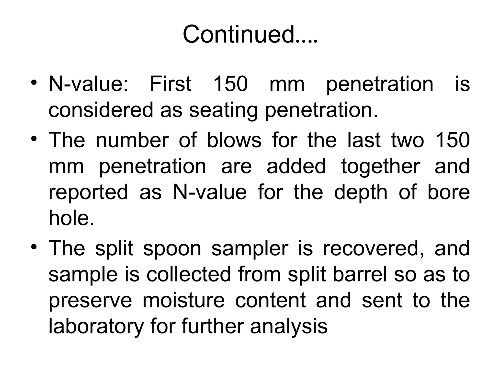
Plate Load Test
Dr. A. D. Katdare
Plate Load Test
(IS 1888 – 1982)
• The ultimate load-bearing capacity of a
foundation, as well as the allowable
bearing capacity based on tolerable
settlement considerations, can be
effectively determined from the field load
test.
• It is generally referred to as the plate
load test
Continued….
• The plates that are used for tests in the
field are usually made of steel and are 25
mm (1 in.) thick and 150 mm to 762 mm (6
in. to 30 in.) in diameter. Occasionally,
square plates that are 305 mm × 305 mm
are also used.
Test Setup
Test setup
• A test pit is dug at site up to the depth at which
the foundation is proposed to be laid.
• The width of the pit should be at least 5 times the
width of the test plate.
• At the centre of the pit a small square depression
or hole is made whose size is equal to the size of
the test plate and bottom level of which
corresponds to the level of actual foundation.
• The depth of the hole should be such that the
ratio of depth to width of the loaded area is
approximately the same as the ratio of the actual
depth to width of the foundation.
• The mild steel plate (also known as bearing
plate) used in the test should not be less than
25 mm in thickness and its size may vary from
300 to 750 mm.
• The plate could be square or circular in shape.
• Circular plate is adopted in case of circular
footing and square plate is used in all other
types of footings.
• The plate is machined on side and edges.
Test setup
Testing Procedure
• The load is applied to the test plate through a
centrally placed column. The test load is
transmitted to the column by one of the
following two methods
• (i) Gravity loading or reaction loading method
(ii) Loading truss method
Gravity loading: Test setup
A loading platform is constructed over the column placed on
the test plate and test load is applied by placing dead weight
in the form of sand bags, concrete blocks, etc. on the
platform.
Reaction loading
• Many a times a hydraulic jack is placed
between the loading platform and the
column top for applying the load to the test
plate – the reaction of the hydraulic jack
being borne by the loaded platform.
• This form of loading is termed as reaction
loading.
Reaction loading
Some a times a hydraulic jack is placed between the loading platform and the
column top for applying the load to the test plate – the reaction of the hydraulic jack
being borne by the loaded platform. This form of loading is termed as reaction
loading.
Test procedure
• When the load is applied to the test plate, it starts sinking
slowly. The settlement of the plate is recorded to an
accuracy of 0.02 mm with the help of sensitive dial
gauges.
• At least two dial gauges are used to account for
differential settlement. The dial gauges are placed at
diametrically opposite ends of the plate and one dial
gauge is mounted on independently supported references
beam or datum rod.
• As the plate sinks, the ram of the dial gauge moves down
and the settlement is recorded.
• The magnitude of load is indicated on the load-gauge of
the hydraulic jack. The load is applied in regular
increment of about 2KN or 1/5th of the
expected ultimate bearing capacity, whichever is less.
• Settlement should be observed for each increment of
load after an interval of 1, 4, 10, 20,40 and 60 minutes
and thereafter at hourly intervals until the rate of
settlement becomes less than 002 mm per hour. The
maximum load to be applied for the test should be about
15 times the expected ultimate bearing capacity of the
soil.
Test procedure
• Load is applied in the predefined
increments
• Settlement of the plate is observed from the
dial gauge readings. Settlement should be
observed for each increment of load after 1,
4, 10, 20, 40 and 60 minutes and thereafter
at hourly interval until the rate of settlement
becomes less than about 0.02 mm per
hour. Enter the readings in the tabular form
• Load versus settlement curve is plotted
Test procedure
Interpretation of the results
Load versus settlement curve
Safe bearing capacity (SBC) based on permissible settlement.
Curve A: This type curve is obtained
in case of loose to medium cohesion
less soil (i.e. 15 < N < 30). This type
of curve shows no clear point of
failure.
Curve B: This type curve is obtained
in case of cohesive soil. As the load
increases the curve leans toward
settlement curve.
Curve C: This type curve is obtained
in case of partially cohesive soil (i.e.
C-phi soil). This type of curve also
does not show a clear point of failure.
Curve D: This type curve is obtained
in case of dense cohesionless soil
(i.e. N > 30). This type of curve is
common in case of dense sand or
gravel deposits.
Interpretation of the results
Limitations of plate load test
• The test results reflect only the character of
the soil located within a depth of less than
twice the width of bearing plate.
• Normally the foundations are larger than the
test plates.
• The Plate Load Test being of short
duration, does not give the ultimate
settlements particularly in case of cohesive
soils.
• For clayey soils the bearing capacity (from
shear consideration) for a large foundation,
is almost same as that for the smaller test
plate.
• But in dense sandy soils the bearing
capacity increases with the size of the
foundation and hence the test with smaller
size test plate tends to give conservative
values in dense sandy soils.
Limitations of plate load test
Calculation of bearing capacity
Effect of size of plate on bearing capacity
For sands and gravels
For clayey soils
f
f p
p
B
q q
B
 
  
 
 
f p
q q

Effect of size of plate on settlement –
For sandy soils, the following relation can be used:
For clayey soils, the following relation can be used:
2
( 0.3)
( 0.3)
f p
f p
p f
B B
s s
B B
 

  

 
 
f
f p
p
B
s s
B

Calculation of settlement
Example
• A plate load test was conducted using a plate
of 0.75m*0.75m size, on a uniform deposit of
sand and the following data were obtained:
Pressure (KN/m2
) Settlement (mm)
0 0
50 1.5
100 2
200 4
300 7.5
400 12.5
500 20
600 40.6
• Calculate the safe bearing
capacity of soil taking
factor of safety as 2.5.
• Calculate settlement of a
square footing of size
2mx2m at safe bearing
capacity
Solution
So Safe bearing capacity (qsafe) = Ultimate bearing capacity
(qult) / Factor of safety = 500 / 2.5 = 200 kN/m2
Example
• In practical and assignment
Standard Penetration test (SPT)
SPT
• SPT is a most commonly used in-situ
method.
• SPT is suitable for cohesionless soil, which
cannot be sampled easily.
• The test is usually used for determining
relative density and angle of internal friction
of soil.
• It is also used to determine unconfined
compressive strength.
SPT test setup
diagram
Standard Penetration Test (SPT)
• Components
– Drilling Equipment
– Inner diameter of hole 100 to 150 mm
– Casing may be used in case of soft/non-cohesive
soils
– Split spoon sampler IS:9640-1980
– Drive weight assembly
– Falling Weight = 63.5 Kg
– Fall height = 75 cm
– Others like Lifting bail, Tongs, ropes, screw jack,
etc.
Procedure: SPT
• The bore hole is advanced to desired depth
and bottom is cleaned.
• Split spoon sampler is attached to a drill rod
and rested on bore hole bottom.
• Driving mass is dropped onto the drill rod
repeatedly and the sampler is driven into soil
for a distance of 450 mm.
• The number of blow for each 150 mm
penetration are recorded.
Continued….
• N-value: First 150 mm penetration is
considered as seating penetration.
• The number of blows for the last two 150
mm penetration are added together and
reported as N-value for the depth of bore
hole.
• The split spoon sampler is recovered, and
sample is collected from split barrel so as to
preserve moisture content and sent to the
laboratory for further analysis
Observations on SPT
• Under the following conditions the
penetration is referred to as refusal and
test is halted.
– 50 blows are required for any 150 mm
penetration
– 100 blows are required for last 300 mm
penetration
– 10 successive blows produce no
advancement
Precautions during SPT
• The height of free fall Must be 750 mm
• The fall of hammer must be free, frictionless and
vertical
• Cutting shoe of the sampler must be free from
wear & tear
• The bottom of the bore hole must be cleaned to
collect undisturbed sample
• When SPT is done in a sandy soil below water
table , the water level in the bore hole MUST be
maintained higher than the ground water level.
Corrections to SPT N
• Dilatancy correction
• Overburden correction
Overburden correction is applied first and dilatancy
correction is applied thereafter.
Use of N
Pressuremeter test
Dr. A. D. Katdare
Department of Civil Engineering
SGI, Atigre
Introduction
• In 1957, Louis Menard, French Civil
engineer, developed a simple equipment
for in-situ testing of soil.
• The use of the pressuremeter is to
measure lateral mearth pressure, calculate
bearing capacity, settlement etc.
Principle
• This is in-situ test for soil
testing.
• The principle is to introduce a
cylindrical probe with a flexible
cover which can expand
radially, in a borehole.
• A pressure is applied by the on
the wall of the hole, and the soil
deformation is measured, by
measuring the volume increase
of the hole (via probe).
Principle
Fig. Pressure versus volume for
pressuremeter test
Parts of the curve:
1.Inflation of the probe
cover so as to obtain the
contact between the
probe and the walls of
the hole.
2.Pseudo-elastic reaction
of the soil against the
probe
3.Large displacements of
the soil against probe
pressure
Parameters from pressuremeter test
• Em : the Menard modulus used in
calculation of settlement of foundations
• PL : Limit pressure used for calculation of
bearing capacity of soil with regards to
specific foundation
• Pf : the creep pressure used for stress
path calculations.
Equipment
• The radial expansion is
obatained through probe.
• The applied pressure is
obtained through natural
gas (nitrogen) (because
it is cheap and simple)
• The applied pressure
and radial deformation is
measured through
monitoring box.
• Connecting tube (tubing)
Fig. Pressuremeter test
setup
Probe
Actual probe used for
test.
Inflated probe with end
effects.
Probe
1. Guard cells are necessary to impose radial strain and
for the confinement of central probe.
2. Central measuring cell is used for inflating and
measuring the cell pressure.
Test procedure
• Probe bleeding: Inflating the probe for the
initial part before start of the test (till the
probe touch the boundaries)
• This resistance is measured and then
subtracted from the soil resistance to get
actual soil resistance.
Calculation
• After performing the test, the graph of
pressure versus displacement is plotted.
• The required quantity like (settlement,
bearing capacity etc) is calculated from
related parameter (like Em, PL etc.)
Summary
• Pressuremeter test is a in-situ test for
calculation of the parameters like bearing
capacity, settlement etc.
• It is useful for cohesive and cohesionless
soil both.
Assignment 2 --- Unit II
1. Explain modes of failure for soil.
2. Explain plate load test in detail with respect to
– Test setup
– Calculations for bearing capacity and settlement)
3. Explain SPT in detail with respect to
– Test setup
– Procedure
– N Value
– Correction to N value
4. Explain pressuremeter test in detail
– Test setup
– Use in calculation of various parameters in Geotechnical
Engineering
Date of submission: 29/01/2016 (All batches)
Termwork
Unit II
• Exercise 3
– Calculate bearing capacity by Terzaghi’s
method
• Exercise 4
– Calculate bearing capacity by IS code method
• Exercise 5
– Detailed description and calculation of bearing
capacity and settlement using plate load test
data with critical comment on load settlement
curve
End of Unit II

IN situ soil testing_Soil Mechanics Foundation

  • 1.
    Plate Load Test Dr.A. D. Katdare
  • 2.
    Plate Load Test (IS1888 – 1982) • The ultimate load-bearing capacity of a foundation, as well as the allowable bearing capacity based on tolerable settlement considerations, can be effectively determined from the field load test. • It is generally referred to as the plate load test
  • 3.
    Continued…. • The platesthat are used for tests in the field are usually made of steel and are 25 mm (1 in.) thick and 150 mm to 762 mm (6 in. to 30 in.) in diameter. Occasionally, square plates that are 305 mm × 305 mm are also used.
  • 4.
  • 5.
    Test setup • Atest pit is dug at site up to the depth at which the foundation is proposed to be laid. • The width of the pit should be at least 5 times the width of the test plate. • At the centre of the pit a small square depression or hole is made whose size is equal to the size of the test plate and bottom level of which corresponds to the level of actual foundation. • The depth of the hole should be such that the ratio of depth to width of the loaded area is approximately the same as the ratio of the actual depth to width of the foundation.
  • 6.
    • The mildsteel plate (also known as bearing plate) used in the test should not be less than 25 mm in thickness and its size may vary from 300 to 750 mm. • The plate could be square or circular in shape. • Circular plate is adopted in case of circular footing and square plate is used in all other types of footings. • The plate is machined on side and edges. Test setup
  • 7.
    Testing Procedure • Theload is applied to the test plate through a centrally placed column. The test load is transmitted to the column by one of the following two methods • (i) Gravity loading or reaction loading method (ii) Loading truss method
  • 8.
    Gravity loading: Testsetup A loading platform is constructed over the column placed on the test plate and test load is applied by placing dead weight in the form of sand bags, concrete blocks, etc. on the platform.
  • 9.
    Reaction loading • Manya times a hydraulic jack is placed between the loading platform and the column top for applying the load to the test plate – the reaction of the hydraulic jack being borne by the loaded platform. • This form of loading is termed as reaction loading.
  • 10.
    Reaction loading Some atimes a hydraulic jack is placed between the loading platform and the column top for applying the load to the test plate – the reaction of the hydraulic jack being borne by the loaded platform. This form of loading is termed as reaction loading.
  • 11.
    Test procedure • Whenthe load is applied to the test plate, it starts sinking slowly. The settlement of the plate is recorded to an accuracy of 0.02 mm with the help of sensitive dial gauges. • At least two dial gauges are used to account for differential settlement. The dial gauges are placed at diametrically opposite ends of the plate and one dial gauge is mounted on independently supported references beam or datum rod. • As the plate sinks, the ram of the dial gauge moves down and the settlement is recorded.
  • 12.
    • The magnitudeof load is indicated on the load-gauge of the hydraulic jack. The load is applied in regular increment of about 2KN or 1/5th of the expected ultimate bearing capacity, whichever is less. • Settlement should be observed for each increment of load after an interval of 1, 4, 10, 20,40 and 60 minutes and thereafter at hourly intervals until the rate of settlement becomes less than 002 mm per hour. The maximum load to be applied for the test should be about 15 times the expected ultimate bearing capacity of the soil. Test procedure
  • 13.
    • Load isapplied in the predefined increments • Settlement of the plate is observed from the dial gauge readings. Settlement should be observed for each increment of load after 1, 4, 10, 20, 40 and 60 minutes and thereafter at hourly interval until the rate of settlement becomes less than about 0.02 mm per hour. Enter the readings in the tabular form • Load versus settlement curve is plotted Test procedure
  • 14.
    Interpretation of theresults Load versus settlement curve Safe bearing capacity (SBC) based on permissible settlement.
  • 15.
    Curve A: Thistype curve is obtained in case of loose to medium cohesion less soil (i.e. 15 < N < 30). This type of curve shows no clear point of failure. Curve B: This type curve is obtained in case of cohesive soil. As the load increases the curve leans toward settlement curve. Curve C: This type curve is obtained in case of partially cohesive soil (i.e. C-phi soil). This type of curve also does not show a clear point of failure. Curve D: This type curve is obtained in case of dense cohesionless soil (i.e. N > 30). This type of curve is common in case of dense sand or gravel deposits. Interpretation of the results
  • 16.
    Limitations of plateload test • The test results reflect only the character of the soil located within a depth of less than twice the width of bearing plate. • Normally the foundations are larger than the test plates. • The Plate Load Test being of short duration, does not give the ultimate settlements particularly in case of cohesive soils.
  • 17.
    • For clayeysoils the bearing capacity (from shear consideration) for a large foundation, is almost same as that for the smaller test plate. • But in dense sandy soils the bearing capacity increases with the size of the foundation and hence the test with smaller size test plate tends to give conservative values in dense sandy soils. Limitations of plate load test
  • 18.
    Calculation of bearingcapacity Effect of size of plate on bearing capacity For sands and gravels For clayey soils f f p p B q q B          f p q q 
  • 19.
    Effect of sizeof plate on settlement – For sandy soils, the following relation can be used: For clayey soils, the following relation can be used: 2 ( 0.3) ( 0.3) f p f p p f B B s s B B            f f p p B s s B  Calculation of settlement
  • 20.
    Example • A plateload test was conducted using a plate of 0.75m*0.75m size, on a uniform deposit of sand and the following data were obtained: Pressure (KN/m2 ) Settlement (mm) 0 0 50 1.5 100 2 200 4 300 7.5 400 12.5 500 20 600 40.6 • Calculate the safe bearing capacity of soil taking factor of safety as 2.5. • Calculate settlement of a square footing of size 2mx2m at safe bearing capacity
  • 21.
    Solution So Safe bearingcapacity (qsafe) = Ultimate bearing capacity (qult) / Factor of safety = 500 / 2.5 = 200 kN/m2
  • 22.
  • 23.
  • 24.
    SPT • SPT isa most commonly used in-situ method. • SPT is suitable for cohesionless soil, which cannot be sampled easily. • The test is usually used for determining relative density and angle of internal friction of soil. • It is also used to determine unconfined compressive strength.
  • 25.
  • 26.
    Standard Penetration Test(SPT) • Components – Drilling Equipment – Inner diameter of hole 100 to 150 mm – Casing may be used in case of soft/non-cohesive soils – Split spoon sampler IS:9640-1980 – Drive weight assembly – Falling Weight = 63.5 Kg – Fall height = 75 cm – Others like Lifting bail, Tongs, ropes, screw jack, etc.
  • 27.
    Procedure: SPT • Thebore hole is advanced to desired depth and bottom is cleaned. • Split spoon sampler is attached to a drill rod and rested on bore hole bottom. • Driving mass is dropped onto the drill rod repeatedly and the sampler is driven into soil for a distance of 450 mm. • The number of blow for each 150 mm penetration are recorded.
  • 28.
    Continued…. • N-value: First150 mm penetration is considered as seating penetration. • The number of blows for the last two 150 mm penetration are added together and reported as N-value for the depth of bore hole. • The split spoon sampler is recovered, and sample is collected from split barrel so as to preserve moisture content and sent to the laboratory for further analysis
  • 29.
    Observations on SPT •Under the following conditions the penetration is referred to as refusal and test is halted. – 50 blows are required for any 150 mm penetration – 100 blows are required for last 300 mm penetration – 10 successive blows produce no advancement
  • 30.
    Precautions during SPT •The height of free fall Must be 750 mm • The fall of hammer must be free, frictionless and vertical • Cutting shoe of the sampler must be free from wear & tear • The bottom of the bore hole must be cleaned to collect undisturbed sample • When SPT is done in a sandy soil below water table , the water level in the bore hole MUST be maintained higher than the ground water level.
  • 31.
    Corrections to SPTN • Dilatancy correction • Overburden correction Overburden correction is applied first and dilatancy correction is applied thereafter.
  • 32.
  • 33.
    Pressuremeter test Dr. A.D. Katdare Department of Civil Engineering SGI, Atigre
  • 34.
    Introduction • In 1957,Louis Menard, French Civil engineer, developed a simple equipment for in-situ testing of soil. • The use of the pressuremeter is to measure lateral mearth pressure, calculate bearing capacity, settlement etc.
  • 35.
    Principle • This isin-situ test for soil testing. • The principle is to introduce a cylindrical probe with a flexible cover which can expand radially, in a borehole. • A pressure is applied by the on the wall of the hole, and the soil deformation is measured, by measuring the volume increase of the hole (via probe).
  • 36.
    Principle Fig. Pressure versusvolume for pressuremeter test Parts of the curve: 1.Inflation of the probe cover so as to obtain the contact between the probe and the walls of the hole. 2.Pseudo-elastic reaction of the soil against the probe 3.Large displacements of the soil against probe pressure
  • 37.
    Parameters from pressuremetertest • Em : the Menard modulus used in calculation of settlement of foundations • PL : Limit pressure used for calculation of bearing capacity of soil with regards to specific foundation • Pf : the creep pressure used for stress path calculations.
  • 38.
    Equipment • The radialexpansion is obatained through probe. • The applied pressure is obtained through natural gas (nitrogen) (because it is cheap and simple) • The applied pressure and radial deformation is measured through monitoring box. • Connecting tube (tubing) Fig. Pressuremeter test setup
  • 39.
    Probe Actual probe usedfor test. Inflated probe with end effects.
  • 40.
    Probe 1. Guard cellsare necessary to impose radial strain and for the confinement of central probe. 2. Central measuring cell is used for inflating and measuring the cell pressure.
  • 41.
    Test procedure • Probebleeding: Inflating the probe for the initial part before start of the test (till the probe touch the boundaries) • This resistance is measured and then subtracted from the soil resistance to get actual soil resistance.
  • 42.
    Calculation • After performingthe test, the graph of pressure versus displacement is plotted. • The required quantity like (settlement, bearing capacity etc) is calculated from related parameter (like Em, PL etc.)
  • 43.
    Summary • Pressuremeter testis a in-situ test for calculation of the parameters like bearing capacity, settlement etc. • It is useful for cohesive and cohesionless soil both.
  • 44.
    Assignment 2 ---Unit II 1. Explain modes of failure for soil. 2. Explain plate load test in detail with respect to – Test setup – Calculations for bearing capacity and settlement) 3. Explain SPT in detail with respect to – Test setup – Procedure – N Value – Correction to N value 4. Explain pressuremeter test in detail – Test setup – Use in calculation of various parameters in Geotechnical Engineering Date of submission: 29/01/2016 (All batches)
  • 45.
    Termwork Unit II • Exercise3 – Calculate bearing capacity by Terzaghi’s method • Exercise 4 – Calculate bearing capacity by IS code method • Exercise 5 – Detailed description and calculation of bearing capacity and settlement using plate load test data with critical comment on load settlement curve
  • 46.