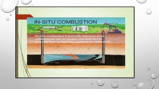
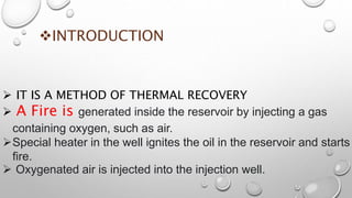
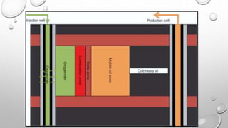
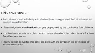
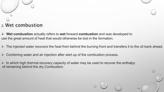
A
POWER POINT PRESENTATION
ON
IN-SITU COMBUSTION, AIR REQUIREMENT FOR IN SITU COMBUSTION
PRESENTED BY-ankit panar
PRESENTED TO- Asst.Prof. rajesh sharma
Ajmer institute of technology, ajmer (RAJ.)
 TABLE OF CONTENT
 INTRODUCTION
 TECHNIQUES AND
PROCEDURE INVOLVED
METHODS
 ISC PATTERN
CHARACTERISTIC
CONCLUSION
INTRODUCTION
 IT IS A METHOD OF THERMAL RECOVERY
 A Fire is generated inside the reservoir by injecting a gas
containing oxygen, such as air.
Special heater in the well ignites the oil in the reservoir and starts
fire.
 Oxygenated air is injected into the injection well.
The ISC treatment is an exothermic process
that assists the improvement of oil recovery by
reducing the viscosity of the oil by the
generated heat from the burned oil.
 ISC treatment generates less greenhouse
gas emission since the compressed air is
injected to the reservoir instead of steam.
TECHNIQUES AND PROCEDURE INVOLVED
Most of the oil is driven toward the producer by a combustion of a following:-
1. Gas drive
2. Water drive
Based on the respective direction of front propogation and air flow the process
can be either of the following-
1.Forward
2.Reverse
Gas drive- A recovery mechanism for oil well
containing dissolved gas and free gas, whereby
energy of Expanding gas is to drive oil from the
reservoir formation into the wellbore.
water reservoir-drive mechanism -whereby the oil is driven through the
reservoir by an active aquifer. As the reservoir depletes,
the water moving in from the aquifer below displaces the oil until the
aquifer energy is expended or the well eventually produces too
much water to be viable.
METHODS
1.DRY
COMBUSTION
2.WET
COMBUSTION
1. DRY COMBUSTION –
An in situ combustion technique in which only air or oxygen-enriched air mixtures are
injected into a formation.
 After the ignition, combustion front gets propagated by the continuous flow of the air.
 combustion front acts as a piston which pushes ahead of it the unburnt crude fractions
from the swept zones.
 heavy fraction converted into coke, are burnt with the oxygen in the air injected to
sustain combustion
2. Wet combustion
 Wet combustion actually refers to wet forward combustion and was developed to
use the great amount of heat that would otherwise be lost in the formation.
 The injected water recovers the heat from behind the burning front and transfers it to the oil bank ahead.
 Combining water and air injection after start up of the combustion process.
 In which high thermal recovery capacity of water may be used to recover the enthalpy
of remaining behind the dry Combustion.
ISC PATTERN CHARACTERISTICS
Reservoir thickness should be greater than 10 ft to avoid
excessive heat losses to surrounding formation. However,
very thick formations may present sweep efficiency
problems because of gravity override.

Permeability has to be large enough (greater than
100 md) to allow more flow of the viscous oil and
achieving the desired air injectivity.
•
 Porosity and oil saturation have to be large enough to allow the
economic success of the process
.

The reservoir depth should be large enough to confine the
injected air in the reservoir. In general, there is no depth
limit except that may affect the injection pressure.
CONCLUSION
 ISC AIMS TO RECOVER HYDROCARBONS BY COMBUSTION PROCESS
 RESERVIOR DEPTH SHOULD BE LARGE ENOUGH TO CONFINE THE INJECTED
INTO THE RESERVIOR
NO DEPTH LIMIT WHICH LEADS THE INJECTION PRESSURE .
THANK-YOU

in situ combustion

  • 1.
    A POWER POINT PRESENTATION ON IN-SITUCOMBUSTION, AIR REQUIREMENT FOR IN SITU COMBUSTION PRESENTED BY-ankit panar PRESENTED TO- Asst.Prof. rajesh sharma Ajmer institute of technology, ajmer (RAJ.)
  • 2.
     TABLE OFCONTENT  INTRODUCTION  TECHNIQUES AND PROCEDURE INVOLVED METHODS  ISC PATTERN CHARACTERISTIC CONCLUSION
  • 4.
    INTRODUCTION  IT ISA METHOD OF THERMAL RECOVERY  A Fire is generated inside the reservoir by injecting a gas containing oxygen, such as air. Special heater in the well ignites the oil in the reservoir and starts fire.  Oxygenated air is injected into the injection well.
  • 6.
    The ISC treatmentis an exothermic process that assists the improvement of oil recovery by reducing the viscosity of the oil by the generated heat from the burned oil.  ISC treatment generates less greenhouse gas emission since the compressed air is injected to the reservoir instead of steam.
  • 7.
    TECHNIQUES AND PROCEDUREINVOLVED Most of the oil is driven toward the producer by a combustion of a following:- 1. Gas drive 2. Water drive Based on the respective direction of front propogation and air flow the process can be either of the following- 1.Forward 2.Reverse
  • 8.
    Gas drive- Arecovery mechanism for oil well containing dissolved gas and free gas, whereby energy of Expanding gas is to drive oil from the reservoir formation into the wellbore. water reservoir-drive mechanism -whereby the oil is driven through the reservoir by an active aquifer. As the reservoir depletes, the water moving in from the aquifer below displaces the oil until the aquifer energy is expended or the well eventually produces too much water to be viable.
  • 10.
  • 11.
    1. DRY COMBUSTION– An in situ combustion technique in which only air or oxygen-enriched air mixtures are injected into a formation.  After the ignition, combustion front gets propagated by the continuous flow of the air.  combustion front acts as a piston which pushes ahead of it the unburnt crude fractions from the swept zones.  heavy fraction converted into coke, are burnt with the oxygen in the air injected to sustain combustion
  • 12.
    2. Wet combustion Wet combustion actually refers to wet forward combustion and was developed to use the great amount of heat that would otherwise be lost in the formation.  The injected water recovers the heat from behind the burning front and transfers it to the oil bank ahead.  Combining water and air injection after start up of the combustion process.  In which high thermal recovery capacity of water may be used to recover the enthalpy of remaining behind the dry Combustion.
  • 13.
    ISC PATTERN CHARACTERISTICS Reservoirthickness should be greater than 10 ft to avoid excessive heat losses to surrounding formation. However, very thick formations may present sweep efficiency problems because of gravity override.  Permeability has to be large enough (greater than 100 md) to allow more flow of the viscous oil and achieving the desired air injectivity.
  • 14.
    •  Porosity andoil saturation have to be large enough to allow the economic success of the process .  The reservoir depth should be large enough to confine the injected air in the reservoir. In general, there is no depth limit except that may affect the injection pressure.
  • 15.
    CONCLUSION  ISC AIMSTO RECOVER HYDROCARBONS BY COMBUSTION PROCESS  RESERVIOR DEPTH SHOULD BE LARGE ENOUGH TO CONFINE THE INJECTED INTO THE RESERVIOR NO DEPTH LIMIT WHICH LEADS THE INJECTION PRESSURE .
  • 16.