Download to read offline
![International Journal of VLSI design & Communication Systems (VLSICS) Vol.3, No.4, August 2012
DOI : 10.5121/vlsic.2012.3405 49
Improved Algorithm for Throughput
Maximization in MC-CDMA
Hema Kale1
, C.G. Dethe2
and M.M. Mushrif3
1
ETC Department , Jhulelal Institute of Technology Nagpur , India.
Email: hema.kale72@gmail.com
2
ECE Department, Priyadarshni Institute of Engineering and Technology, Nagpur , India.
Email: cgdethe@yahoo.com
3
ETC Department, Yashwantrao Chavan College of Engineering, Nagpur, India
Email: milindmushrif@yahoo.com
ABSTRACT
The Multi-Carrier Code Division Multiple Access (MC-CDMA) is becoming a very significant downlink
multiple access technique for high-rate data transmission in the fourth generation wireless communication
systems. By means of efficient resource allocation higher data rate i.e. throughput can be achieved. This
paper evaluates the performance of group (subchannel) allocation criteria employed in downlink
transmission, which results in throughput maximization. Proposed algorithm gives the modified technique
of sub channel allocation in the downlink transmission of MC-CDMA systems. Simulation are carried out
for all the three combining schemes, results shows that for the given power and BER proposed algorithm
comparatively gives far better results .
KEYWORDS
SCS, MC-CDMA, UWB, SNR, BER, ACA, APA
1. INTRODUCTION
Resource allocation is a major issue in the performance of wireless networks. Out of the available
resources frequency allocation is the problem which is going to be considered in this paper.
Channel fading is different at different sub carriers, this feature can be exploited for allocating the
subcarriers to the users according to the instantaneous channel state information (CSI).The SCS-
MC-CDMA system as shown in Fig.1 assigns to each user a selected number of sub-carriers
[14]. The concept of sub-carrier selection is introduced to counter the problem of high power
consumption. MC-CDMA systems usually have lots of sub-carriers, by using the appropriate sub-
carrier selection technique, it can be made possible to match the power consumption to the user’s
data rate.
Sub carriers are allocated depending on user’s data or on instantaneous Channel State Information
(CSI). Instantaneous CSI refers to the amount of channel fading user experiences on particular
channel. Some schemes have been proposed in already published papers for subcarrier selection
according to CSI which includes,
• Selecting the subcarrier receiving maximum power on it.
• Selecting the sub-carrier with maximum SNR.](https://image.slidesharecdn.com/3412vlsics05-190108092331/85/Improved-Algorithm-for-Throughput-Maximization-in-MC-CDMA-1-320.jpg)
![International Journal of VLSI design & Communication Systems (VLSICS) Vol.3, No.4, August 2012
DOI : 10.5121/vlsic.2012.3405 49
Improved Algorithm for Throughput
Maximization in MC-CDMA
Hema Kale1
, C.G. Dethe2
and M.M. Mushrif3
1
ETC Department , Jhulelal Institute of Technology Nagpur , India.
Email: hema.kale72@gmail.com
2
ECE Department, Priyadarshni Institute of Engineering and Technology, Nagpur , India.
Email: cgdethe@yahoo.com
3
ETC Department, Yashwantrao Chavan College of Engineering, Nagpur, India
Email: milindmushrif@yahoo.com
ABSTRACT
The Multi-Carrier Code Division Multiple Access (MC-CDMA) is becoming a very significant downlink
multiple access technique for high-rate data transmission in the fourth generation wireless communication
systems. By means of efficient resource allocation higher data rate i.e. throughput can be achieved. This
paper evaluates the performance of group (subchannel) allocation criteria employed in downlink
transmission, which results in throughput maximization. Proposed algorithm gives the modified technique
of sub channel allocation in the downlink transmission of MC-CDMA systems. Simulation are carried out
for all the three combining schemes, results shows that for the given power and BER proposed algorithm
comparatively gives far better results .
KEYWORDS
SCS, MC-CDMA, UWB, SNR, BER, ACA, APA
1. INTRODUCTION
Resource allocation is a major issue in the performance of wireless networks. Out of the available
resources frequency allocation is the problem which is going to be considered in this paper.
Channel fading is different at different sub carriers, this feature can be exploited for allocating the
subcarriers to the users according to the instantaneous channel state information (CSI).The SCS-
MC-CDMA system as shown in Fig.1 assigns to each user a selected number of sub-carriers
[14]. The concept of sub-carrier selection is introduced to counter the problem of high power
consumption. MC-CDMA systems usually have lots of sub-carriers, by using the appropriate sub-
carrier selection technique, it can be made possible to match the power consumption to the user’s
data rate.
Sub carriers are allocated depending on user’s data or on instantaneous Channel State Information
(CSI). Instantaneous CSI refers to the amount of channel fading user experiences on particular
channel. Some schemes have been proposed in already published papers for subcarrier selection
according to CSI which includes,
• Selecting the subcarrier receiving maximum power on it.
• Selecting the sub-carrier with maximum SNR.](https://image.slidesharecdn.com/3412vlsics05-190108092331/75/Improved-Algorithm-for-Throughput-Maximization-in-MC-CDMA-1-2048.jpg)
![International Journal of VLSI design & Communication Systems (VLSICS) Vol.3, No.4, August 2012
50
• Selecting the subcarrier requiring least amount of transmit power on it.
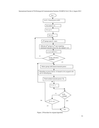
Figure.1 Frame format of sub carrier selecting MC-CDMA system .
Out of which last one method has been implemented for achieving optimum throughput in this
paper.
An appropriate sub-carrier selection technique results in high spectrum efficiency, reduction in
high power consumption at the mobile terminal, high data throughput in a multicell environment,
improvement in BER performance, reduction in signal processing at the mobile terminal.
For the given power, throughput can be maximized by assigning maximum number of
subcarriers to the users.
Here some throughput maximization techniques are given. The maximum throughput of each
code channel can be achieved by employing following techniques,
• If the code channel is allocated to one user.
• If the code channel is allocated to the user who has the highest achieved SINR value with
the same transmit power.
• If all code channels of one group are allocated to only one user.
• If the allocated transmit power of the one particular group is equally distributed over all
code channels of such group.
• If the transmit power over different groups is allocated by water filling method.
In [13] Qingxin Chen, Elvino S. Sousa and Subbarayan pasupathy proposed a Water-filling
algorithm , it was motivated by the water-filling (WF) principle in information theory i.e. given
parallel channels with Gaussian noise, information should be first fed into channels with lower
noise levels to achieve the maximum channel capacity. it improves the speed and average SINR
of the system. One pitfall might lie in the case where one user’s fading amplitudes are much
larger than the average. G.K.D.Prasanna Venkatesan, and C.Ravichandran, has suggested a
dynamic sub-carrier allocation technique for adaptive modulation based MC-CDMA system in
[5] which results in improvement in throughput and BER performance. In this paper water filling
algorithm is used to select the best sub-carrier,over the existing subcarriers. In this the principle
of adaptive modulation consists of allocating many bits to carriers with a high SNR, whereas on
carriers with low SNR only a few or no bits at all are transmitted. However there will be a
possibility that when many channels suffer deep fading then there will be no transmission or very
few bits are transmitted. In [15] the random policy has been described. This random policy is to
allocate the subcarrier randomly regardless of channel information, which is concluded in [15] to
No. of
subcarriers
Pilot symbol
OFDM symbol
ssssesssssssssss
frequency
time
code
Data symbol
Processing gain
gGainGainggGa](https://image.slidesharecdn.com/3412vlsics05-190108092331/85/Improved-Algorithm-for-Throughput-Maximization-in-MC-CDMA-2-320.jpg)
![International Journal of VLSI design & Communication Systems (VLSICS) Vol.3, No.4, August 2012
51
be the best algorithm to get better BER performance. However the increase in system throughput
with increase in SNR is less as compared to other advanced systems of sub carrier allocation. In
[7] Tallal El Shabrawy1 and Tho Le-Ngoc2, has proposed a Subcarrier group assignment for MC-
CDMA wireless etworks resulting in high throughput. In this paper, two interference-based
subcarrier group assignment strategies are introduced for multicell MC-CDMA systems. In least
interfered group assignment (LIGA), users are assigned to groups experiencing minimum
interference. In best channel ratio group assignment (BCRGA), the user is assigned to the
subcarrier group that holds the best ratio of channel response-to-received interference. In [14]
Teruya Fujii, Noboru Izuka, Hiroyoshi Masui, and Atsushi Nagate, has proposed a sub-carrier
selecting MC-CDMA system for 4G systems in which the concept of sub-carrier selection to
counter the problem of high power consumption has been introduced. In this paper the concept is
to assign each user only as many sub-carriers as are needed to support the user’s data rate. In this
method the system complexity increases when more number of filters are required for subcarrier
selection.
In this paper we investigate the method of subchannel allocation to the user for the given transmit
power in the downlink transmission. First the available channels are divided into number of
groups and then this groups are allocated to the users. According to CSI each user will require a
different transmit power on each channel, using this characteristic group of channels will be
allotted to users. In the proposed algorithm the method of group allocation to the users has been
modified which will result in producing global minima. This will result in further saving of the
power and achieving higher throughput as compared with the original algorithm.
The rest of the paper commences with section II giving simplified introduction of original
algorithm. In section III an improved method of subchannel allocation to the users is proposed.
Then simulation results are discussed by considering one specific environment of CDMA
network in section IV. At the end conclusions are presented.
2. Original Algorithm: Adaptive Sub-Carrier Allocation
This algorithm as discussed by Jun-Bo Wang, Ming Chen and Jiangzhou Wang [1] is focuses on
the joint channel and power allocation in the downlink transmission of multi-user MC-CDMA
systems for throughput maximization , under the constraints that the total transmit power should
not exceed the maximum transmit power and each channel’s SINR should not be less than a pre-
defined value.
If the required amount of transmit power of each channel has been determined for all users before
the channel allocation, then throughput maximization problem is given by a following
optimization of c
୳
problem as,
(1)
Where
܋
ܝ
- number of the uth
user’s channels on the gth
group.
U - Total number of users
G - Total number of groups of subcarriers.
Problem (1) is subject to](https://image.slidesharecdn.com/3412vlsics05-190108092331/85/Improved-Algorithm-for-Throughput-Maximization-in-MC-CDMA-3-320.jpg)
![International Journal of VLSI design & Communication Systems (VLSICS) Vol.3, No.4, August 2012
52
(1.a)
(1.b)
Where
S – Total number of subcarriers in gth
group.
Above equation (1.b) is the total transmit power constraint.
where
PT
max
- The maximum transmit power, and
ࢍ
࢛- The required transmit power for uth
user on one channel of the gth
group,it is expressed as,
݃
ݑ = ߚNoS−2
∑ ห߱݃,ݏ
ݑ ห
2ܵ
1=ݏ ∑ ቚ߱݃,ݏ
ݑ ݂݃,ݏ
ݑ
ቚ
−2
ܵ
1=ݏ (2)
Where
ࢼ- Target threshold of BER.
݂݃,ݏ
ݑ
− uth
user’s channel fading on the sth
subcarrier of the desired group
߱݃,ݏ
ݑ - uth
user’s frequency domain combining weight for the signal on the sth
subcarrier of the
desired group
Denoting u୫୧୬ as the user whose transmit power for one channel on the gth
group is minimum
among all users, i.e.
u୫୧୬ = arg minଵஸ୳ஸ ൛p
୳
ൟ (3)
2.1 Criteria used for group allocation
In the original scheme [1] the criteria used for group of channels allocation can be defined as,
each group is assigned to the user who requires the minimum transmit power for one channel on
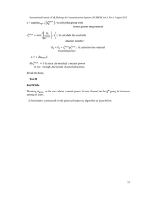
that group. As shown in fig. 2 group allocation starts from first group.
In the original scheme the subcarriers are allocated to the different users by,
1) Calculating required power on each channel of all groups.
2) A group is assigned to the user who requires minimum transmit power for one channel on
that group,
3) Starting from the first group, it will scan all the U no. of users and the user requiring minimum
power will be allocated the first group.
4) Next second group will scan remaining (U-1) users, and the user requiring min. power will be
allocated the second group and so on………
Refer flowchart for the above adaptive channel allocation algorithm which is constructed as
below in fig. 2, it was not given in the earlier paper,](https://image.slidesharecdn.com/3412vlsics05-190108092331/85/Improved-Algorithm-for-Throughput-Maximization-in-MC-CDMA-4-320.jpg)
![International Journal of VLSI design & Communication Systems (VLSICS) Vol.3, No.4, August 2012
54
3. Proposed Improved Algorithm For Subchannel Allocation
An improved algorithm is proposed for the channel allocation in the downlink transmission of
multi-user MC-CDMA systems for throughput maximization, under the constraints that the total
transmit power should not exceed the maximum transmit power and each channel’s SINR should
not be less than a pre-defined value.
In the Proposed algorithm group assignment technique is modified by finding out the global
minima while allocating groups to the users. The subsequent chnnel allocation within the selected
group is the same as in the original algorithm [1].
The proposed algorithm is explained as given below,
3.1. Criteria used for group allocation
In the proposed modified scheme, the group of subcarriers are allocated to the different users by,
1) Calculating required transmit power on each channel of all groups.
2) while allocating groups to the users, all the M number of groups will scan all the K number of
users at the same time and the user requiring minimum transmit power on any one channel of any
group will be allocated that group.
3) Next remaining (G -1) number of groups will scan all the remaining (U -1) number of users
and so on…….
The proposed improved algorithm is as follows
۷ܖܗܑܜ܉ܢܑܔ܉ܑܜܑܖ
Pୖ = P
୫ୟ୶
, C = ሼ1,2, … , Gሽ, c
୳
= 0 for
u = 1, … , U and g = 1, … , G.
۵ܘܝܗܚ ܜܖ܍ܕܖܑܛܛ܉
܍ܔܑܐܟ C ≠ ø
u =1:U
g = 1: G
[p୫୧୬, u୫୧୬] = min(min൛p
୳
ൟ) % allocate a group to user
requiring least power on one channel of that group
end
Channel allocation
܍ܔܑܐܟ C ≠ ø](https://image.slidesharecdn.com/3412vlsics05-190108092331/85/Improved-Algorithm-for-Throughput-Maximization-in-MC-CDMA-6-320.jpg)
![International Journal of VLSI design & Communication Systems (VLSICS) Vol.3, No.4, August 2012
56
Figure. 3 flowchart for proposed algorithm
Different combining schemes will result in different power allocation, accordingly required
transmit power (p୫
୩
) will change as per Table1[1] . Therefore throughput will be different for
different combining schemes.
no
Remaining groups scan
remaining users
Start
Set PT = Transmit power at BTS
Set counter C = G
Set c
୳
= 0
All groups scan all users
Allocate gth
group to uth
user requiring minimum
transmit power for one channel in it.
G = G -1 and U = U-1
Group allocation
complete
Select group with lowest transmit power requirement
Depending on power find no. of channels to be assigned
to the user of selected group
Find residual transmit power- PR
C = C - 1
Is PR
enough
If C = 0
End
yes
nono
yes
yes](https://image.slidesharecdn.com/3412vlsics05-190108092331/85/Improved-Algorithm-for-Throughput-Maximization-in-MC-CDMA-8-320.jpg)
![International Journal of VLSI design & Communication Systems (VLSICS) Vol.3, No.4, August 2012
57
TABLE I..
REQUIRED POWER FOR COMBINING SCHEMES
MRC EGC ZFC
p
୳
βN୭Sିଶ
ห݂,௦
௨
ห
ଶ
ௌ
௦ୀଵ
ห݂,௦
௨
ห
ିସ
ௌ
௦ୀଵ
ߚN୭Sିଵ
ห݂,௦
௨
ห
ିଶ
ௌ
௦ୀଵ
ߚN୭Sିଵ
ห݂,௦
௨
ห
ିଶ
ௌ
௦ୀଵ
Effectiveness of above algorithm depends on with changing CSI how the matrix ൛P
୳
ൟ is formed.
Matrix ൛P
୳
ൟ will be the (G x U) matrix of which elements are dependent on CSI.
4. Simulation results
For carrying out simulations the environment is selected as given below in table 2. It is assumed
that the CSI is available at the base station. The parameter describing CSI is the channel fading
parameter ( f ), which is to be applied as input in the proposed algorithm and output is the no. of
channels allocated for the given total transmit power (PT ).
TABLE II.
SIMULATION PARAMETERS
Parameter Environment
Total no. of channels
(N)
128
Total no. of groups (G) 8
Total no.of users (U) 8
BER 10(-2)
Channel fading (f) 0-12dB
Noise power spectral
density (No)
0.16 watts/Hz
Target SINR value (β) -2ln5BER
Frequency domain combining weights will be different for different combining schemes and
accordingly throughput will vary for Minimal ratio combining (MRC), Equal gain combining
(EGC) and Zero force combining (ZFC) schemes[1].
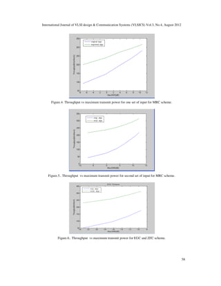
Simulations are carried out for the environment selected as in table 2. First combining scheme
under consideration is MRC. For one set of input parameters(f) , the total power (PT ) is varied
and the throughput obtained is shown in fig.4. Similarly for different sets of inputs we will get
number of variations, for one of the set of such inputs a much better result is obtained as shown in
fig.5. In both the cases as transmit power increases throughput increases. one can clearly notice
that proposed algorithm gives significant improvement in the throughput obtained.
In fig. 6 throughput versus the maximum transmit power is obtained for EGC and ZFC schemes.
As both combining schemes requires same amount of transmit power for one same channel, the
throughput obtained is same for EGC and ZFC scheme as can be seen in fig.6. Comparatively in
this case for EGC and ZFC combining schemes all the channels get allocated for a much less
power for near about -9dB.
Fig.7 is intended for modified algorithm only for three combining schemes. One can observe that
in this case with EGC, ZFC combining schemes much higher throughput is obtained at a very
little power as compared to MRC scheme.](https://image.slidesharecdn.com/3412vlsics05-190108092331/85/Improved-Algorithm-for-Throughput-Maximization-in-MC-CDMA-9-320.jpg)
![International Journal of VLSI design & Communication Systems (VLSICS) Vol.3, No.4, August 2012
59
Figure.7. Throughput vs maximum transmit power power using modified algorithm.
5. CONCLUSIONS
In this paper an improved algorithm for throughput maximization is proposed. It gives an
adaptive group assignment technique such that the available power at the base station will be
utilized efficiently and maximum no. of channels will be allocated to the users.
Simulation results shows that the proposed algorithm gives much better results as compared to
original one for all the three combining schemes. The future work can be carried out by first
employing adaptive grouping of users and then applying proposed algorithm for group allocation.
REFERENCES
[1] Jun-Bo Wang b, Ming Chen a, Jiangzhou Wang a, “Adaptive channel and power allocation of
downlink multi-user MC-CDMA systems” Computers and Electrical Engineering 35 (2009) 622–633
(Elsevier journal )
[2] Jun-Bo Wang1, Hua-Min Chen2, Ming Chen2, and Xinhua Xue2,” Adaptive Subcarrier Grouping for
Downlink MC-CDMA Systems with MMSE Receiver” 2010 IEEE.
[3] G.K.D. Prasanna Venkatesan and V.C. Ravichandran, “Performance analysis of MC-CDMA for
wideband channels”, Information technology journal,2007 Asian Network for scientific Information.
[4] Teruya Fujii, Noboru Izuka, Hiroyoshi Masui, and Atsushi Nagate,”A proposal of sub-carrier
selecting MC-CDMA system for 4G systems”, 2005 IEEE.
[5] G.K.D.Prasanna Venkatesan, and V.C.Ravichandran, “Performance analysis of dynamic sub-carrier
allocation technique for adaptive modulation based MC-CDMA system”, JCSNS International
Journal of Computer Science and Network Security, VOL.7 No.2, February 2007.
[6] Dhananjay Kumar,C. Chellappan, “Efficient resource allocation in MC-CDMA cellular wireless
networks t o support multimedia traffic”, Journal of Theoretical and Applied Information
Technology 2009.
[7] Tallal El Shabrawy1 and Tho Le-Ngoc2, “Subcarrier group assignment for MC-CDMA wireless
networks”, EURASIP Journal on Wireless Communications and Networking Volume 2007,](https://image.slidesharecdn.com/3412vlsics05-190108092331/85/Improved-Algorithm-for-Throughput-Maximization-in-MC-CDMA-11-320.jpg)
![International Journal of VLSI design & Communication Systems (VLSICS) Vol.3, No.4, August 2012
60
[8] Teruya Fujii, Noboru Izuka, Hiroyoshi Masui, and Atsushi Nagate,”SCS-MC-CDMA system with
Best effort cell structure”, 2005 IEEE.
[9] Koichi Sueda, Atsushi Nagate, Hiroyoshi Masui and Teruya Fujii, “Peak Power Reduction Method
for MC-CDMA System”, 2006 IEEE.
[10] Jianli Xie',Cuiran Li', Chengshu Li2 , “Analysis of multicarrier CDMA system with adaptive
subcarrier and power allocation” 2007 IEEE Proceedings of IWSDA'07.
[11] Jivesh Govil, Jivika Govil, “An impirical feasibility study of 4G’s key technologies” 2008 IEEE.
[12] S. Hara and R. Prasad, “Overview of multicarrier CDMA,”IEEE communications Magazine, vol. 35,
no. 12, pp. 126–133, Dec. 1997.
[13] Qingxin Chen, Elvino S. Sousa and Subbarayan Pasupathy ,“Multicarrier CDMA with adaptive
frequency hopping for mobile radio systems” , IEEE journal on selected areas in communications,
vol. 14, no 9, december 1996.
[14] Teruya Fujii, Noboru Izuka, Hiroyoshi Masui, and Atsushi Nagate,”A proposal of sub-carrier
selecting MC-CDMA system for 4G systems”, 2005 IEEE.
[15] M. Tabulo and et. al, ”A linear programming algorithm for a grouped MC-CDMA system,” Proc.
IEEE VTC’03, vol. 3, pp. 1463-1467, Oct. 2003.](https://image.slidesharecdn.com/3412vlsics05-190108092331/85/Improved-Algorithm-for-Throughput-Maximization-in-MC-CDMA-12-320.jpg)

The document presents an improved algorithm for maximizing throughput in multi-carrier code division multiple access (MC-CDMA) systems, addressing resource allocation in downlink transmissions. It evaluates sub-channel allocation techniques, proposing a modified method that optimally assigns groups of subcarriers to users based on their instantaneous channel state information, aiming for higher data rates and reduced power consumption. The algorithm is validated through simulations, demonstrating better performance over existing techniques.