Download as PDF, PPTX

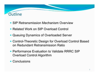
![Wh t i SIP?
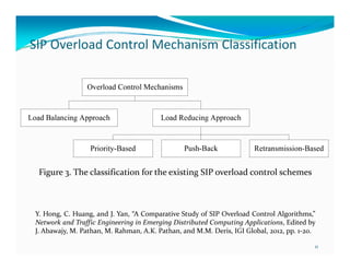
What is SIP?
Session Initiation Protocol
protocol that establishes,
Internet
manages (multimedia)
sessions [RFC 3261]
used for VoIP presence &
VoIP,
video conference
Proxy
Server
Proxy
Server
SIP consists of two basic
elements
l
t
UA (User Agent) and P-Server
(Proxy Server)
About 1000 companies produce
SIP products
Microsoft’s Windows
Messenger (≥4 7) i l d SIP
M
(≥4.7) includes
UA
UA
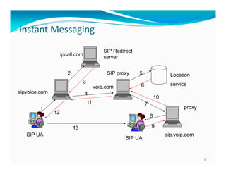
Simplified SIP Network Configuration
2](https://image.slidesharecdn.com/implicitsipoverloadcontrolieeeglobecom201021oct2013-131021112750-phpapp02/85/Mitigating-SIP-Overload-Using-a-Control-Theoretic-Approach-2-320.jpg)
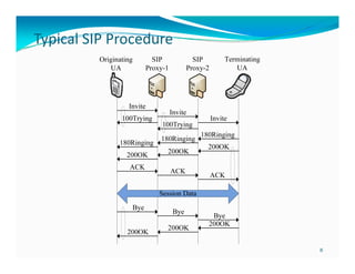
![IMS SIP Server Overload – A
f
h ll
Performance Management Challenge
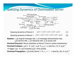
3GPP has adopted SIP
as the basis of IMS architecture
Problem: Server(s) cannot complete
the processing of requests under
overload conditions
Multiple causes: Insufficient
p
capacity, Component Failures,
Unexpected traffic surges, DOS
attacks [RFC 5390]
Impact: Performance degradation,
drop in throughput, revenue loss,
network collapse
Simplified
Si lifi d IMS C t l L
Control Layer O
Overview
i
4](https://image.slidesharecdn.com/implicitsipoverloadcontrolieeeglobecom201021oct2013-131021112750-phpapp02/85/Mitigating-SIP-Overload-Using-a-Control-Theoretic-Approach-4-320.jpg)
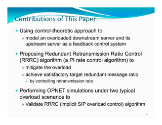
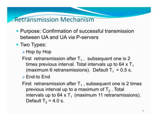
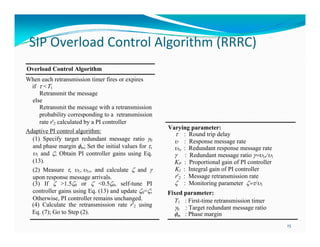
![Overload Controller Design
g
Redundant message ratio (t)=1r(t)/1(t) r'2(t)/1(t)
PI controller regulates retransmission rate r'2(t)
r
t
'
r2 (t) KPe(t ) KI 0 e()d
t
KP ( 0 (t )) KI 0 ( 0 ())d
Control plant P(s)=(s)/r'2(s)=[r'2(s)e-s/1]/r'2(s)=e-s/1
PI controller C(s)=KP+KI/s
Open-loop overload control system G(s)=C(s)P(s)=(KP+KI/s)e-s/1
Positive phase margin m of G(s) can guarantee control system stability
PI controller gains can be obtained based on phase margin m
KP
1
2
KI
1 (3 / 4 m )
2
14](https://image.slidesharecdn.com/implicitsipoverloadcontrolieeeglobecom201021oct2013-131021112750-phpapp02/85/Mitigating-SIP-Overload-Using-a-Control-Theoretic-Approach-14-320.jpg)
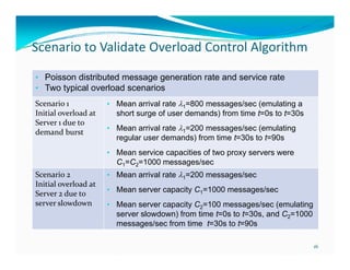

This document summarizes a paper presented at IEEE GLOBECOM 2010. The paper proposes a control-theoretic approach called Redundant Retransmission Ratio Control (RRRC) algorithm to model and mitigate SIP server overload as a feedback control problem. The RRRC algorithm uses a PI controller to regulate the message retransmission rate to maintain a target redundant message ratio and overcome server overload conditions. OPNET simulations of two overload scenarios validate that the RRRC algorithm can effectively prevent overload propagation and cancel overload.


