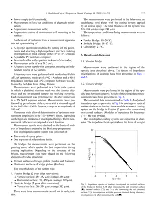
This document summarizes research using electrochemical impedance spectroscopy (EIS) to evaluate the protective properties of paint coatings on two bridges. EIS measurements were taken in the laboratory and in situ on the bridges. The results showed:
1) EIS provided information about coating properties like resistance, capacitance, and barrier effectiveness.
2) Coatings on external bridge surfaces exhibited high impedance and barrier properties. Coatings on internal surfaces showed signs of water penetration over time.
3) In situ bridge coating measurements correlated well with laboratory coating measurements, indicating EIS can effectively evaluate coatings on structures.
![Progress in Organic Coatings 46 (2003) 216–219
Impedance measurements of coating properties on bridge structures
J. Bordziłowskia, K. Darowickia,∗, S. Krakowiaka, A. Królikowskab
a Department of Anticorrosion Technology, Technical University of Gdansk, 80-952 Gda´nsk, 11/12 Narutowicza, Poland
b Road and Bridges Research Institute, Warsaw, Poland
Received 13 September 2001; received in revised form 7 June 2002; accepted 3 September 2002
Abstract
Impedance measurements allow early evaluation of the protective properties of paint coatings and linings. They are applied for comparison
of coatings, monitoring of their properties and determination of the protection mechanism. This methodology is being used more and more
frequently in laboratory investigations. On site studies are more difficult due to the need of using complex computer controlled apparatus and
its susceptibility to atmospheric conditions, electric fields and mechanical damage. In this lecture a proposal has been made of application
of the impedance methodology of paint coating evaluation in “in situ” conditions on bridges. Good correlation has been stated with results
obtained in the laboratory, allowing application of this methodology for non-destructive evaluation of the properties of thick coatings and
organic linings on industrial structures.
© 2002 Elsevier Science B.V. All rights reserved.
Keywords: Electrochemical impedance spectroscopy; Organic coatings; Steel bridges
1. Introduction
Impedance techniques are becoming more and more
important in the evaluation of properties of metals and
coatings on a metal substrate [1–25]. In the initial period of
application of the impedance method it found application in
investigations of the corrosion rate of different metals and
thin porous coatings and was used mainly in basic research
[1–8]. In 1989, based on these investigations, the ASTM G
106-89 standard was issued in USA [9], which determined
the methodology of impedance measurements in labora-
tory conditions. This standard determined the procedure
for investigation of metals in 0.005 M sulphuric acid and
0.495 M aqueous sodium sulphate solution to verify the ap-
paratus and algorithm of impedance measurements. These
investigations were performed in a 3-electrode system at
the stationary potential or one provided by a potentiostat.
More recently, the impedance methodology began to find
wider application in investigations of organic coatings. In
this way in 1984 a conference “Application of Electro-
chemical al Techniques to Organic Coatings” was organ-
ised in Genoa by Prof. P.L. Bonora, and attended by such
well-known scientists as Funke, Delouis, Scantlebury and
Drazic. Initially, thin coatings were investigated, and next,
with improvement of measurement apparatus and computer
∗ Corresponding author. Tel.: +48-58-472483; fax: +48-583471092.
E-mail address: zak@chem.pg.gda.pl (K. Darowicki).
techniques, investigations were initiated of coatings up to
1 mm in thickness, and lately of linings up to 10 mm [10–25].
The first results of “in situ” measurements performed in a
scrubber of a flue gas desulphurisation plant (IOS) were pre-
sented at a conference in Poraj in November 2000 [26,27].
The aim of this paper is to present the summary of results
obtained on bridge structures. The scope of performed in-
vestigations was as follows:
• Investigations on bridge structures;
• Control measurements in the laboratory.
This paper presents the comparison of coatings on two
bridges over the Vistula River (the bridges in Fordon and in
Swiecie) with results obtained in laboratory conditions for
an analogous coating system.
2. Experimental
Impedance on site investigations of coating systems re-
quire specially prepared apparatus. The main assumptions
of the apparatus system are:
• High internal impedance of the measurement system;
• Measurements in a 2-electrode system;
• Measurement frequency range: at least 10−5 to 10−1 Hz;
• Adjusted amplitude of the measurement signal in the
range to maximum 500 mV;
0300-9440/02/$ – see front matter © 2002 Elsevier Science B.V. All rights reserved.
PII: S0300-9440(02)00193-5](https://image.slidesharecdn.com/impedancemeasurementsofcoatingpropertiesonbridgestructures-150513103741-lva1-app6892/85/Impedance-measurements-1-320.jpg)
![Progress in Organic Coatings 46 (2003) 216–219
Impedance measurements of coating properties on bridge structures
J. Bordziłowskia, K. Darowickia,∗, S. Krakowiaka, A. Królikowskab
a Department of Anticorrosion Technology, Technical University of Gdansk, 80-952 Gda´nsk, 11/12 Narutowicza, Poland
b Road and Bridges Research Institute, Warsaw, Poland
Received 13 September 2001; received in revised form 7 June 2002; accepted 3 September 2002
Abstract
Impedance measurements allow early evaluation of the protective properties of paint coatings and linings. They are applied for comparison
of coatings, monitoring of their properties and determination of the protection mechanism. This methodology is being used more and more
frequently in laboratory investigations. On site studies are more difficult due to the need of using complex computer controlled apparatus and
its susceptibility to atmospheric conditions, electric fields and mechanical damage. In this lecture a proposal has been made of application
of the impedance methodology of paint coating evaluation in “in situ” conditions on bridges. Good correlation has been stated with results
obtained in the laboratory, allowing application of this methodology for non-destructive evaluation of the properties of thick coatings and
organic linings on industrial structures.
© 2002 Elsevier Science B.V. All rights reserved.
Keywords: Electrochemical impedance spectroscopy; Organic coatings; Steel bridges
1. Introduction
Impedance techniques are becoming more and more
important in the evaluation of properties of metals and
coatings on a metal substrate [1–25]. In the initial period of
application of the impedance method it found application in
investigations of the corrosion rate of different metals and
thin porous coatings and was used mainly in basic research
[1–8]. In 1989, based on these investigations, the ASTM G
106-89 standard was issued in USA [9], which determined
the methodology of impedance measurements in labora-
tory conditions. This standard determined the procedure
for investigation of metals in 0.005 M sulphuric acid and
0.495 M aqueous sodium sulphate solution to verify the ap-
paratus and algorithm of impedance measurements. These
investigations were performed in a 3-electrode system at
the stationary potential or one provided by a potentiostat.
More recently, the impedance methodology began to find
wider application in investigations of organic coatings. In
this way in 1984 a conference “Application of Electro-
chemical al Techniques to Organic Coatings” was organ-
ised in Genoa by Prof. P.L. Bonora, and attended by such
well-known scientists as Funke, Delouis, Scantlebury and
Drazic. Initially, thin coatings were investigated, and next,
with improvement of measurement apparatus and computer
∗ Corresponding author. Tel.: +48-58-472483; fax: +48-583471092.
E-mail address: zak@chem.pg.gda.pl (K. Darowicki).
techniques, investigations were initiated of coatings up to
1 mm in thickness, and lately of linings up to 10 mm [10–25].
The first results of “in situ” measurements performed in a
scrubber of a flue gas desulphurisation plant (IOS) were pre-
sented at a conference in Poraj in November 2000 [26,27].
The aim of this paper is to present the summary of results
obtained on bridge structures. The scope of performed in-
vestigations was as follows:
• Investigations on bridge structures;
• Control measurements in the laboratory.
This paper presents the comparison of coatings on two
bridges over the Vistula River (the bridges in Fordon and in
Swiecie) with results obtained in laboratory conditions for
an analogous coating system.
2. Experimental
Impedance on site investigations of coating systems re-
quire specially prepared apparatus. The main assumptions
of the apparatus system are:
• High internal impedance of the measurement system;
• Measurements in a 2-electrode system;
• Measurement frequency range: at least 10−5 to 10−1 Hz;
• Adjusted amplitude of the measurement signal in the
range to maximum 500 mV;
0300-9440/02/$ – see front matter © 2002 Elsevier Science B.V. All rights reserved.
PII: S0300-9440(02)00193-5](https://image.slidesharecdn.com/impedancemeasurementsofcoatingpropertiesonbridgestructures-150513103741-lva1-app6892/75/Impedance-measurements-1-2048.jpg)
![218 J. Bordziłowski et al. / Progress in Organic Coatings 46 (2003) 216–219
Fig. 2. Impedance spectra of coatings investigated on horizontal surface
of the bridge in Fordon 0.5 h after immersing the cell () and 24 h after
immersing the cell (ᮀ, ᭺), in comparison with the spectrum obtained
during laboratory investigations 2 h after immersing the cell (᭹).
Fig. 3. Impedance spectra of coatings investigated on vertical surface
on the bridge in Swiecie on the reference area of the girder 0.5 h after
immersion of the cell (, ᭺) in comparison with the spectrum obtained
in laboratory investigations 2 h after immersion of the cell (᭹).
Table 1
Electric parameters of coatings obtained from impedance measurements for bridges in Fordon and Swiecie
Measurement position Impedance modulus,
log[Z(1 kHz)] ( cm2)
Coating resistance,
RC (G cm2)
Coating capacitance,
CC (pF cm−2)
Coefficient, na
Fordon external vertical surface, 0.5 h 9.86–9.99 13.2–42.6 16.2–21.8 0.97–0.98
Fordon internal vertical surface, 0.5 h 9.32–9.56 2.89–4.40 22.0–34.9 0.91–0.94
Fordon internal vertical surface, 24 h 8.73–9.27 3.11–5.42 29.5–32.3 0.90–0.92
Fordon internal horizontal surface, 0.5 h 9.54–9.97 1.16–14.30 11.6–15.5 0.97–0.98
Fordon internal horizontal surface, 24 h 8.13–9.21 1.09–4.23 48.5–61.1 0.90–0.92
Swiecie vertical surface, 0.5 h 8.71–8.73 0.39–0.66 48.5–53.1 0.92–0.93
a Coefficient of impedance spectrum depression.
lines inclined at an angle of 45◦ in relation to the abscissa
axis.
On internal surfaces of the bridge, where more moist
conditions are found, a slight bend of the curve was stated
already 0.5 h after immersing the cells, at frequencies of
approximately 20 Hz, indicating a frequency-resistive char-
acter of the dependency, pointing to water reaching the
metal base. In this case a decrease of the impedance mod-
ulus to the value |Z(f)| = 3 G was observed case of
measurements performed 24 h after immersing the coating
a distinct decrease of the impedance spectrum has been
noticed without change of its shape, pointing to penetra-
tion of water into the coating and a change of the associ-
ated dielectric constant of the external coating layer. This
point to insufficient resistance of the coating to action of
water, especially in conditions of continuous presence of
moisture.
In the case of the bridge in Swiecie after 3 years of ex-
posure (Fig. 3) on vertical, less moist surfaces a capacitive-
resistive character of curves was observed as soon as 0.5 h
after immersing the cells and the presence of the so called
“resistive paths” in the coating, enabling access of water to
the metal surface and development of electrode processes
on the metal-coating phase interface. A relatively high value
of the logarithm of the impedance modulus (approximately
8.7) indicates maintaining of high protective properties in
these regions.
Analysis of the curves presented in Fig. 2 concerning coat-
ings on horizontal surfaces (0.5 h after immersing the cell)
indicates maintenance of the barrier character of the eva-
luated coating system in the case of coatings on the bridge
in Fordon (2 years of operation). For this system, the
impedance modulus for frequency f = 1 Hz was equal
to 10 G . Measurements performed 24 h after immersing
the cells indicate penetration of water inside the coatings,
this being shown by a small change of the angle of in-
clination of the curve, showing presence of the resistive
component and a decrease of the curve resulting from a
change of the dielectric constant of the external part of the
coating.
Results of calculations of electric circuit parameters ob-
tained through correlation analysis of the equivalent electric
circuit confirm conclusions from the graphical analysis
of impedance spectra. Classical parallel RCCC electric](https://image.slidesharecdn.com/impedancemeasurementsofcoatingpropertiesonbridgestructures-150513103741-lva1-app6892/85/Impedance-measurements-3-320.jpg)
![J. Bordziłowski et al. / Progress in Organic Coatings 46 (2003) 216–219 219
equivalent circuit was applied. Coatings inside the bridge
in Fordon are characterised by a lower resistance RC,
higher capacitance CC and lower coefficient “n” in com-
parison with coatings on external surfaces. The coeffi-
cient “n” describes the depression of impedance spectrum
in Nyquist plots. In Bode plot the coefficient “n” de-
scribes the departure of inclination from theoretical value
d log |Z(f)|/d log(f) = −1. Twenty-four hours after im-
mersing the cells electric parameters of coatings change
(the resistance decreased, the capacitance increased and
the coefficient “n” decreased), indicating penetration of
water inside the coatings. However, the determined pa-
rameters such as impedance modulus and coefficient “n”
point to good protective properties of coatings in both
locations.
4. Summary
Investigations have shown that the epoxy-polyurethane
coating system on the steel structure of two bridges after a 2
and 3 years exploitation period is still characterised by high
protective properties in regions of lower moisture presence.
The tested coatings, in spite of high initial barrier prop-
erties, show susceptibility to penetration by water. Lower
barrier properties in shaded places point to this and on
horizontal surfaces under the platform plate, which are
frequently moist, as well as a distinct decrease of barrier
properties during 24 h of coating exposure under affixed
measurement cells.
Results of “on site” measurements of the coatings were
similar to those obtained in laboratory conditions.
Acknowledgements
The work was financed by Grant DS10 Technical Univer-
sity of Gda´nsk.
References
[1] F. Mansfeld, Corrosion 29 (1973) 397.
[2] C. Gabrielli, Identification of Electrochemical Process by Frequency
Response Analysis, Solartron Instrumentation Group, 1980.
[3] I. Epelboin, M. Keddam, H. Takenouti, J. Appl. Electrochem. 2
(1972) 71.
[4] W.J. Lorenz, F. Mansfeld, Corros. Sci. 21 (1981) 647.
[5] K. Darowicki, Corros. Sci. 39 (1997) 39.
[6] M.W. Kendig, E.M. Meyer, G. Lindberg, F. Mansfeld, Corros. Sci.
23 (1983) 1007.
[7] J.O. Bockris, A.K.N. Reddy, Modern Electrochemistry, Plenum Press,
New York, 1970.
[8] F. Mansfeld, Evaluation of Corrosion Protection Methods with
Electrochemical Impedance Spectroscopy, in: Proceedings of Corro-
sion’1987, Paper 481, San Francisco, March 1987.
[9] R.D. Armstrong, M.F. Bell, A.A. Metcalfe, The AC impedance of
complex electrochemical reactions, Electrochemistry 6 (1976).
[10] ASTM Designation: G 106-89 (Reapproved 1994), Standard Practise
for Verification of Algorithm and Equipment for Electrochemical
Impedance Measurements.
[11] F. Mansfeld, M.W. Kendig, S. Tsai, Corrosion 38 (1982) 478.
[12] K. Jùtner, Werk. Korros. 36 (1985) 120.
[13] G.W. Walter, Corros. Sci. 26 (1986) 681.
[14] J. Titz, Corrosion 46 (1990) 221.
[15] M.W. Kendig, Corrosion 46 (1990) 22.
[16] A. Miszczyk, K. Darowicki, Polish J. Appl. Chem. 42 (1998) 71.
[17] F. Mansfeld, M.W. Kendig, Corrosion 41 (1985) 490.
[18] S. Feliu, J.C. Galvan, M. Morcillo, Prog. Org. Coat. 17 (1989) 143.
[19] A. Miszczyk, J. Bordziłowski, Farbe Lack 95 (1989) 564.
[20] A. Miszczyk, J. Bordziłowski, Farbe Lack 96 (1990) 860.
[21] H.P. Hack, J.R. Scully, J. Electrochem. Soc. 138 (1991) 231.
[22] M. Kendig, J.R. Scully, Corrosion 46 (1990) 22.
[23] J.N. Murray, H.P. Hack, Corrosion 48 (1992) 671.
[24] A. Miszczyk, K. Darowicki, Z. Klenowicz, Corrosion 53 (1999) 572.
[25] J. Bordziłowski, A. Miszczyk, Z. Klenowicz, Evaluation of thick
organic coatings used for tank conservation, in: Proceedings of the
Colloquium Technical Inspection and Storage Tanks Repairs, Gda´nsk,
1994, p. 185.
[26] J. Bordziłowski, K. Darowicki, S. Krakowiak, A. Królikowska,
Impedance measurements “on site”, in: Proceedings of the Seventh
Polish Symposium on the New Achievements and Corrosion Investi-
gations, Poraj, 2000, p. 317.
[27] S. Krakowiak, K. Darowicki, J. Bordziłowski, Anti-Corros. Meth. M
48 (2001) 358.](https://image.slidesharecdn.com/impedancemeasurementsofcoatingpropertiesonbridgestructures-150513103741-lva1-app6892/85/Impedance-measurements-4-320.jpg)


![Polymer [ बहुलक ] Chemistry Notes PDF - Irfanullah Mehar - JJ Sir Chemistry.pdf](https://cdn.slidesharecdn.com/ss_thumbnails/polymerchemistrynotespdf-irfanullahmehar-jjsirchemistry-260210172118-3f9b37f7-thumbnail.jpg?width=640&height=640&fit=bounds)


