Downloaded 103 times


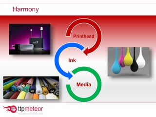
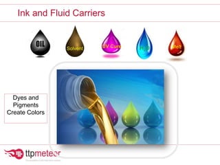
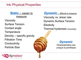

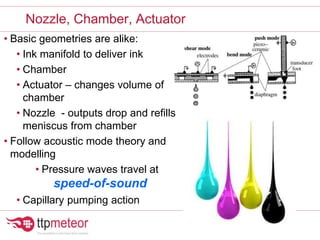
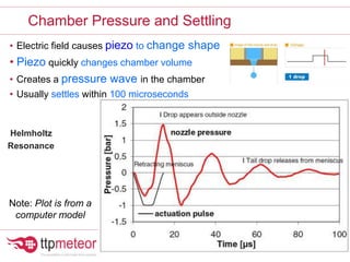
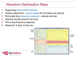
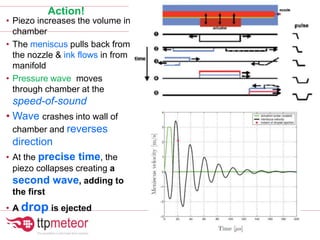
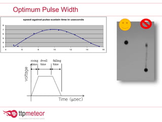
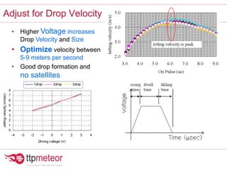
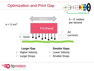


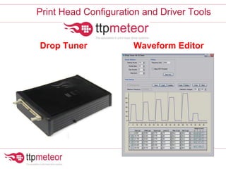
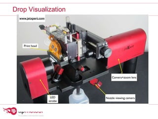


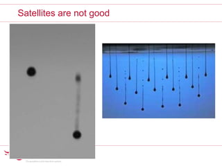
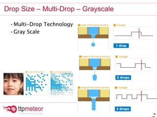
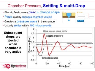
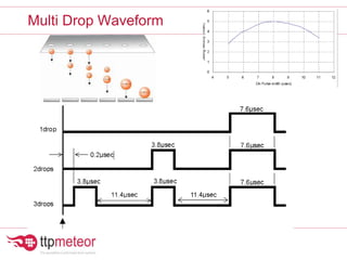
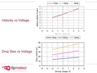
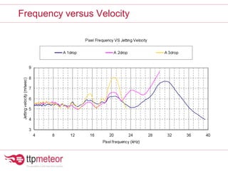


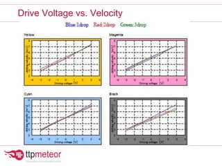
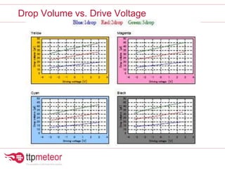
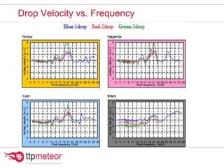
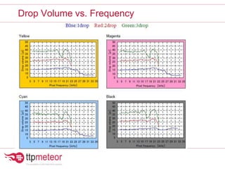
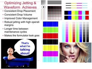


The document discusses optimizing inkjet printhead performance through waveform design and drop visualization. It describes how printhead architecture works to eject ink drops via piezoelectric actuation. Key aspects of optimization include adjusting pulse width to control single drop velocity and size, multi-drop waveform design for grayscale printing, and using measurement equipment to visualize drops and optimize characteristics like velocity and volume. The goal is to achieve consistent, uniform drops for improved color management and print quality.


