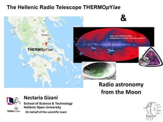
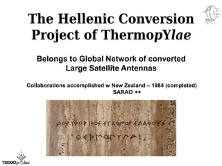
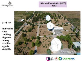
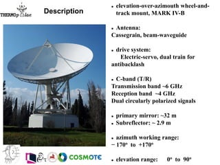
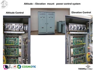
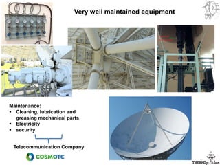
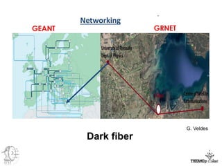
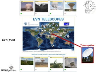
The Hellenic Radio Telescope THERMOpYlae
THERMOpYlae
School of Science & Technology
Hellenic Open University
On behalf of the scientific team
Nectaria Gizani
Radio astronomy
from the Moon
&
• Alternative way to obtain a state of the art radio telescope,
which would have been un-affordable otherwise
• On-going research and development projects among radio
astronomers and engineers in various countries (developing+
developed countries, eg. Ghana,UK) to convert telecomn
antennas into radio telescopes + develop countries via Radio
astronomy
Global network
• Conversion of redundant telecoms instruments: various dish
designs, manufacturers, diameters, mechanics, electrical,
software physical environments, RFI, problems resulting from
social environments, etc
not a trivial task
Dish Conversion
The Hellenic Conversion
Project of ThermopYlae
Belongs to Global Network of converted
Large Satellite Antennas
Collaborations accomplished w New Zealand – 1984 (completed)
SARAO ++
Nippon Electric Co. (NEC)
1982
Used for
monopulse
Auto
tracking
of geosta
tionary
satellite
signals
at 4 GHz
 elevation-over-azimouth wheel-and-
track mount, MARK IV-B
 Antenna:
Cassegrain, beam-waveguide
 drive system:
Electric-servo, dual train for
antibacklash
 C-band (T/R)
Transmission band ~6 GHz
Reception band ~4 GHz
Dual circularly polarized signals
 primary mirror: ~32 m
 Subreflector: ~ 2.9 m
 azimuth working range:
− 170o to +170o
 elevation range: 0o to 90o
Description
Antenna Feed Subsystem
Mark IV-B: 4 reflector
beam guide feed system
Composite feed fixed
on floor of foundation
building
communication
equipment installed in
same building
Tapered waveguide
Receiver Main passive components
• Tapered waveguide
• TM01 mode coupler
• 4, 6 GHz OMT (OrthoMode
Transducer)
• 4/6 GHz high performance Polarizer
Low Noise Amplifier (LNA)
• Dual system for safety
• 60 dB amplification
• Uses cooler system
Servo - Motor power control system
Altitude – Elevation mount power control system
Altitude Control Elevation Control
Control System
• The console for the
antenna tracking control
Very well maintained equipment
Telecommunication Company
Maintenance:
 Cleaning, lubrication and
greasing mechanical parts
 Electricity
 security
Done so far – Future
1) Feasibility Report – 1st iteration done
for example, need to check mechanical parts
2) Some preliminary RFI measurements with and
omnidirectional antenna initially
Up to 15 GHz, no other RFI except from mobile emission –
reception band
 make detailed RFI measurements
(eg. towards antenna pointing directions)
 and monitoring
Upgradable spectrum and network analyzer – up to 9GHz – with a
directional antenna
Of course need to:
Done so far → Future
3) in Greece →
Report  technical recommendations
In conclusion we think that Thermopylae I antenna is in
an excellent position to become a radio telescope soon, if funding
is secured. We are very optimistic from the assessment of what we
have seen, and we have offered further assistance in any possible way.
4) Trip to Institute of Radioastronomy, AUT, Auckland, NZ
Know – how on our sister antenna conversion
5) Using existing C-band feed system check with the spectrum analyzer
what we can detect/measure
Emilio Enriquez + Nectaria Gizani
Set up
7) point to astrophysical sources and check with the spectrum analyzer
what we can detect/measure
SUN
Increase in receiving flux  noise level
ONOFF
Dark fiber
G. Veldes
ThermopYlae
EVN, VLBI
Stations used:
[['EFSLBERG' '50.336028' '6.884439' '5']
['ONSALA' '57.2184' '11.92' '6']
['YEBES' '40.524669' '-3.086861' '8']
['GBT' '38.433131' '-79.839839' '9']
['VLBA_NL' '41.7713888889' '-90.4261111111' '13']
['VLBA-FD' '30.635' '-102.055277778' '14']
['VLBA-LA' '35.775' '-105.754444444' '15']
['VLBA-PT' '34.3008333333' '-107.880833333' '16']
['VLBA-KP' '31.9561111111' '-110.387777778' '17']
['VLBA-OV' '37.2313888889' '-117.723055556' '18']
['VLBA-BR' '48.1311111111' '-118.316944444' '19']
['VLBA-MK' '19.8011111111' '-154.544722222' '20']
['SRT' '39.493056' '-9.244722' '100']]
UV – plots w and w/out ThermopYlae
By Emilio Enriquez
W
H
y
the
H
E
LL
E
N
I
C
A
N
T
E
N
N
A
W ThermpYlae
Hellenic antenna:
• fill in the inner region  "large scale structure".
• provides some of the largest baselines  higher angular resolution
1.67 GHz
Enriquez & Gizani
Sagittarius A
M87
Enriquez & Gizani
1.67 GHz
w ThermopYlae
M31
Enriquez & Gizani
w ThermopYlae
1.67 GHz
Future Plans
• Follow JJ suggestions
• Higher frequencies (≥10 GHz) S-, X- bands
• Install dual polarization 6 GHz receiver, bandwidth 300MHz -
6′.5 resoln → detect fringes, Pointing and sensitivity
measurements
• Implement interface of the control system – PLC,
(movement of antenna, limit switches)
 Allow for azimuth movement +/- 270o
implement software to allow tracking in celestial coordinate system
Ultra wide Band Receiver?
Check
• Mechanical Parts
• Dish surface accuracy, gravitational deformation
Photogrammetry 
most likely by New Year
Together w mechanical part checking
Future Plans
In Operation
- Stand-alone single dish observations
(Total Intensity & Polarization, continuum + spectral line mode)
- operate the antenna at L-band, 23′.6 resoln ??
– need detailed RFI monitoring
- Linked in the Very Long Baseline Interferometry
(Total Intensity & Polarization, continuum + spectral line mode, eg. EVN, VLBI)
→ increase sensitivity of interferometer
Other Functionalities
- Deep space telecommunications
- SETI searches – commensal and dedicated ::
Breakthrough Listen Project - backend
Radio astronomy from the Moon
Why – Science: Far side Moon best place to monitor low-frequency radio waves
Earth: below 10 to 30 MHz radiation blocked by the atmosphere
too much interference from human activity (eg. maritime communication
and short-wave broadcasting,
ionosphere blocks the longest wavelengths
https://sci.esa.int/documents/34375/36249/1567260083880-ESA-CAS-workshop1_poster7_Radioastronomy-Science-from-the-Moon_P-Zarka.pdf
 learn about Dark Ages and the Cosmic Dawn by mapping extremely remote
hydrogen clouds
Radio astronomy from the Moon
2012: ESA Call:: Cosmic Vision
All sky Radio telescope - distributed
aperture of 9 satellites, each with tripole
antennas
 1 central Mothership, 8 spherically
distributed Daughters
LC low-cost, low maintenance formation of
slowly moving spacecrafts, in low relative –
drift orbit
 provide the first extragalactic low-
frequency survey with high sensitivity
(~55 mJy /year) and high resolution (1.1
arcmin @ 30 km): could detect up to 2
million new sources ++.
 Three main observing modes:
a) All-Sky Imaging with omnidirectional
spatial resolution, time resolution of 1-10
seconds, frequency range from
0.1 MHz up to 30 MHz,
b) Rapid Burst Monitoring using all sky
imaging and 100 ms integrations for
responding to rapid solar and galactic
events,
c) Targeted Burst Monitoring, a
beamforming mode to phase the array for
observation of transient radio sources and
variable planetary emissions.
SURO-LC
Provide overlap region @ (20-30) MHz for
source verification:
ground telescopes – problems: Earth's
ionosphere, local radio frequency
interference.
https://www.isispace.nl/projects/ncle-the-netherlands-china-low-frequency-explorer/
NCLE: three co-located, 5-meter
long orthogonal, monopole antenna
elements mounted perpendicular to
the upper side of Chang’e 4 satellite.
Sensitive in (1 - 80 MHz) radio
frequency range, can go down to 80
kHz with reduced sensitivity
 low-frequency regime for radio
astronomy,
 prepare for ground-breaking
observations of the 21-cm line
emission.
•1st mission step: NCLE
10 kg hosted payload on large lunar
orbiter (2018)
•2nd mission step: CLE (~2021)
3 satellites with an inter-satellite link for
real-time interferometry (now studied in
SYSNOVA LUCE)
•3rd mission goal (~2030)
50 – 250 nodes in lunar orbit for an
orbiting radio telescope
Science:
- Constraining the 21-cm line Dark Ages and Cosmic Dawn signal,
- measuring the auroral radio emission from the large planets in our Solar
system,
- determining the radio background spectrum at the Earth-Moon L2 point,
studying the Solar activity and space weather at low frequencies,
creation of a new low-frequency map of the radio sky,
- studying the Earth's ionosphere and its interaction, and the detection of
bright pulsars and other radio transient phenomena at very low
frequencies
- access to a previously unexplored frequency regime
- first step towards opening up the virtually unexplored low-frequency
domain for astronomy.
https://www.ru.nl/astrophysics/radboud-radio-lab/projects/netherlands-china-low-frequency-explorer-ncle/
An ultra-long-wavelength radio
telescope on the far-side of the
Moon:
tremendous advantages cf.
Earth-based/orbiting telescopes
1km-diameter wire-mesh
in a 3-5km-diameter lunar crater
on the far-side,
form a sphericalcap reflector.
6–30MHz frequency band
https://www.nasa.gov/directorates/spacetech/niac/2020_Phase_I_Phase_II/lunar_crater_radio_telescope/
April 7, 2020
Thank you
Other antennas as result from own work
The pilot project of the 32m dish Project, is currently
in progress at the premises of HOU in Perivola in
Patras, with the conversion of a 2m C-band satellite
dish into a small radiotelescope capable of recording
the solar flux at 10.7 cm
6 dipole antennas of the Codalema Experiment

Iloa ngizani2020

  • 1.
    The Hellenic RadioTelescope THERMOpYlae THERMOpYlae School of Science & Technology Hellenic Open University On behalf of the scientific team Nectaria Gizani Radio astronomy from the Moon &
  • 2.
    • Alternative wayto obtain a state of the art radio telescope, which would have been un-affordable otherwise • On-going research and development projects among radio astronomers and engineers in various countries (developing+ developed countries, eg. Ghana,UK) to convert telecomn antennas into radio telescopes + develop countries via Radio astronomy Global network • Conversion of redundant telecoms instruments: various dish designs, manufacturers, diameters, mechanics, electrical, software physical environments, RFI, problems resulting from social environments, etc not a trivial task Dish Conversion
  • 3.
    The Hellenic Conversion Projectof ThermopYlae Belongs to Global Network of converted Large Satellite Antennas Collaborations accomplished w New Zealand – 1984 (completed) SARAO ++
  • 4.
    Nippon Electric Co.(NEC) 1982 Used for monopulse Auto tracking of geosta tionary satellite signals at 4 GHz
  • 5.
     elevation-over-azimouth wheel-and- trackmount, MARK IV-B  Antenna: Cassegrain, beam-waveguide  drive system: Electric-servo, dual train for antibacklash  C-band (T/R) Transmission band ~6 GHz Reception band ~4 GHz Dual circularly polarized signals  primary mirror: ~32 m  Subreflector: ~ 2.9 m  azimuth working range: − 170o to +170o  elevation range: 0o to 90o Description
  • 6.
    Antenna Feed Subsystem MarkIV-B: 4 reflector beam guide feed system Composite feed fixed on floor of foundation building communication equipment installed in same building
  • 7.
  • 8.
    Receiver Main passivecomponents • Tapered waveguide • TM01 mode coupler • 4, 6 GHz OMT (OrthoMode Transducer) • 4/6 GHz high performance Polarizer
  • 9.
    Low Noise Amplifier(LNA) • Dual system for safety • 60 dB amplification • Uses cooler system
  • 10.
    Servo - Motorpower control system
  • 11.
    Altitude – Elevationmount power control system Altitude Control Elevation Control
  • 12.
    Control System • Theconsole for the antenna tracking control
  • 13.
    Very well maintainedequipment Telecommunication Company Maintenance:  Cleaning, lubrication and greasing mechanical parts  Electricity  security
  • 14.
    Done so far– Future 1) Feasibility Report – 1st iteration done for example, need to check mechanical parts 2) Some preliminary RFI measurements with and omnidirectional antenna initially Up to 15 GHz, no other RFI except from mobile emission – reception band
  • 15.
     make detailedRFI measurements (eg. towards antenna pointing directions)  and monitoring Upgradable spectrum and network analyzer – up to 9GHz – with a directional antenna Of course need to:
  • 16.
    Done so far→ Future 3) in Greece → Report  technical recommendations In conclusion we think that Thermopylae I antenna is in an excellent position to become a radio telescope soon, if funding is secured. We are very optimistic from the assessment of what we have seen, and we have offered further assistance in any possible way. 4) Trip to Institute of Radioastronomy, AUT, Auckland, NZ Know – how on our sister antenna conversion
  • 17.
    5) Using existingC-band feed system check with the spectrum analyzer what we can detect/measure Emilio Enriquez + Nectaria Gizani Set up
  • 18.
    7) point toastrophysical sources and check with the spectrum analyzer what we can detect/measure SUN
  • 19.
    Increase in receivingflux  noise level ONOFF
  • 20.
  • 21.
  • 22.
    Stations used: [['EFSLBERG' '50.336028''6.884439' '5'] ['ONSALA' '57.2184' '11.92' '6'] ['YEBES' '40.524669' '-3.086861' '8'] ['GBT' '38.433131' '-79.839839' '9'] ['VLBA_NL' '41.7713888889' '-90.4261111111' '13'] ['VLBA-FD' '30.635' '-102.055277778' '14'] ['VLBA-LA' '35.775' '-105.754444444' '15'] ['VLBA-PT' '34.3008333333' '-107.880833333' '16'] ['VLBA-KP' '31.9561111111' '-110.387777778' '17'] ['VLBA-OV' '37.2313888889' '-117.723055556' '18'] ['VLBA-BR' '48.1311111111' '-118.316944444' '19'] ['VLBA-MK' '19.8011111111' '-154.544722222' '20'] ['SRT' '39.493056' '-9.244722' '100']] UV – plots w and w/out ThermopYlae By Emilio Enriquez W H y the H E LL E N I C A N T E N N A
  • 23.
    W ThermpYlae Hellenic antenna: •fill in the inner region  "large scale structure". • provides some of the largest baselines  higher angular resolution 1.67 GHz Enriquez & Gizani Sagittarius A
  • 24.
    M87 Enriquez & Gizani 1.67GHz w ThermopYlae
  • 25.
    M31 Enriquez & Gizani wThermopYlae 1.67 GHz
  • 26.
    Future Plans • FollowJJ suggestions • Higher frequencies (≥10 GHz) S-, X- bands • Install dual polarization 6 GHz receiver, bandwidth 300MHz - 6′.5 resoln → detect fringes, Pointing and sensitivity measurements • Implement interface of the control system – PLC, (movement of antenna, limit switches)  Allow for azimuth movement +/- 270o implement software to allow tracking in celestial coordinate system Ultra wide Band Receiver?
  • 27.
    Check • Mechanical Parts •Dish surface accuracy, gravitational deformation Photogrammetry  most likely by New Year Together w mechanical part checking
  • 28.
    Future Plans In Operation -Stand-alone single dish observations (Total Intensity & Polarization, continuum + spectral line mode) - operate the antenna at L-band, 23′.6 resoln ?? – need detailed RFI monitoring - Linked in the Very Long Baseline Interferometry (Total Intensity & Polarization, continuum + spectral line mode, eg. EVN, VLBI) → increase sensitivity of interferometer Other Functionalities - Deep space telecommunications - SETI searches – commensal and dedicated :: Breakthrough Listen Project - backend
  • 30.
    Radio astronomy fromthe Moon Why – Science: Far side Moon best place to monitor low-frequency radio waves Earth: below 10 to 30 MHz radiation blocked by the atmosphere too much interference from human activity (eg. maritime communication and short-wave broadcasting, ionosphere blocks the longest wavelengths https://sci.esa.int/documents/34375/36249/1567260083880-ESA-CAS-workshop1_poster7_Radioastronomy-Science-from-the-Moon_P-Zarka.pdf  learn about Dark Ages and the Cosmic Dawn by mapping extremely remote hydrogen clouds
  • 31.
    Radio astronomy fromthe Moon 2012: ESA Call:: Cosmic Vision
  • 33.
    All sky Radiotelescope - distributed aperture of 9 satellites, each with tripole antennas  1 central Mothership, 8 spherically distributed Daughters LC low-cost, low maintenance formation of slowly moving spacecrafts, in low relative – drift orbit  provide the first extragalactic low- frequency survey with high sensitivity (~55 mJy /year) and high resolution (1.1 arcmin @ 30 km): could detect up to 2 million new sources ++.  Three main observing modes: a) All-Sky Imaging with omnidirectional spatial resolution, time resolution of 1-10 seconds, frequency range from 0.1 MHz up to 30 MHz, b) Rapid Burst Monitoring using all sky imaging and 100 ms integrations for responding to rapid solar and galactic events, c) Targeted Burst Monitoring, a beamforming mode to phase the array for observation of transient radio sources and variable planetary emissions. SURO-LC Provide overlap region @ (20-30) MHz for source verification: ground telescopes – problems: Earth's ionosphere, local radio frequency interference.
  • 35.
    https://www.isispace.nl/projects/ncle-the-netherlands-china-low-frequency-explorer/ NCLE: three co-located,5-meter long orthogonal, monopole antenna elements mounted perpendicular to the upper side of Chang’e 4 satellite. Sensitive in (1 - 80 MHz) radio frequency range, can go down to 80 kHz with reduced sensitivity  low-frequency regime for radio astronomy,  prepare for ground-breaking observations of the 21-cm line emission. •1st mission step: NCLE 10 kg hosted payload on large lunar orbiter (2018) •2nd mission step: CLE (~2021) 3 satellites with an inter-satellite link for real-time interferometry (now studied in SYSNOVA LUCE) •3rd mission goal (~2030) 50 – 250 nodes in lunar orbit for an orbiting radio telescope
  • 36.
    Science: - Constraining the21-cm line Dark Ages and Cosmic Dawn signal, - measuring the auroral radio emission from the large planets in our Solar system, - determining the radio background spectrum at the Earth-Moon L2 point, studying the Solar activity and space weather at low frequencies, creation of a new low-frequency map of the radio sky, - studying the Earth's ionosphere and its interaction, and the detection of bright pulsars and other radio transient phenomena at very low frequencies - access to a previously unexplored frequency regime - first step towards opening up the virtually unexplored low-frequency domain for astronomy. https://www.ru.nl/astrophysics/radboud-radio-lab/projects/netherlands-china-low-frequency-explorer-ncle/
  • 37.
    An ultra-long-wavelength radio telescopeon the far-side of the Moon: tremendous advantages cf. Earth-based/orbiting telescopes 1km-diameter wire-mesh in a 3-5km-diameter lunar crater on the far-side, form a sphericalcap reflector. 6–30MHz frequency band https://www.nasa.gov/directorates/spacetech/niac/2020_Phase_I_Phase_II/lunar_crater_radio_telescope/ April 7, 2020
  • 38.
  • 39.
    Other antennas asresult from own work The pilot project of the 32m dish Project, is currently in progress at the premises of HOU in Perivola in Patras, with the conversion of a 2m C-band satellite dish into a small radiotelescope capable of recording the solar flux at 10.7 cm 6 dipole antennas of the Codalema Experiment