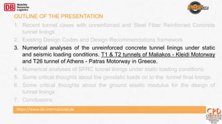
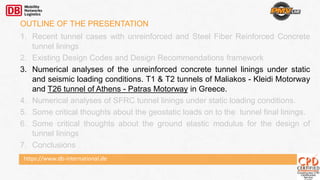
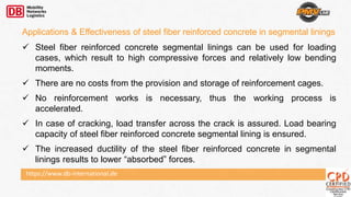
Major issues to be considered for the successful application of unreinforced and steel fiber reinforced concrete (SFRC) tunnel final linings concepts include:
1) Application limits related to the geotechnical environment, seismic regime, and topography that must be determined based on safety and serviceability requirements.
2) Existing design codes and recommendations provide frameworks for evaluating the safety and serviceability of these lining concepts.
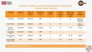
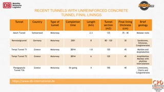
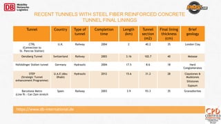
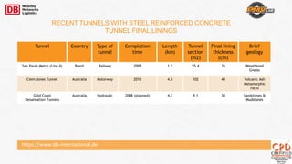
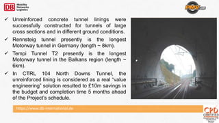
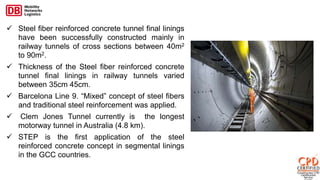
3) Case studies demonstrate that unreinforced and SFRC tunnel linings have been successfully used in tunnels up to 8km and 4.8km respectively, in various ground conditions.

![https://www.db-international.de
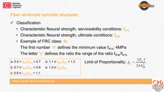
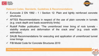
Behavior in tension
Nominal values of the material properties can be determined by performing a
three-point bending test on a notched beam according to EN 14651.
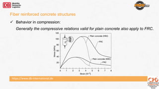
Fiber reinforced concrete structures
Fj[N]: load corresponding to CMOD = CMODj
CMOD: crack mouth opening displacement](https://image.slidesharecdn.com/86e6755f-bcd6-4260-a83d-c83acaf6df14-151014164541-lva1-app6892/85/Ilias-Michalis-PMV-Workshop-Dubai-2014-30-320.jpg)
![https://www.db-international.de
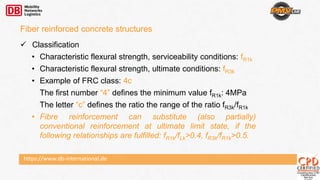
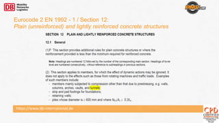
Behavior in tension
Nominal values of the material properties can be determined by performing a
three-point bending test on a notched beam according to EN 14651.
Fiber reinforced concrete structures
Fj[N]: load corresponding to CMOD = CMODj
CMOD: crack mouth opening displacement
fR1
fR3](https://image.slidesharecdn.com/86e6755f-bcd6-4260-a83d-c83acaf6df14-151014164541-lva1-app6892/85/Ilias-Michalis-PMV-Workshop-Dubai-2014-31-320.jpg)