Lyapichev. New RCC dams (Inter. Conf. on RCC, 2003)
•
0 likes•129 views

Seismic analyses of stress-strain state of new type of composed faced symmetrical hardfill dams with central zone of rockfill enriched with cement mortar of different heights & slopes are performed & compared with the traditional gravity RCC dams

Recommended
Recommended
More Related Content
What's hot
What's hot (18)
Similar to Lyapichev. New RCC dams (Inter. Conf. on RCC, 2003)
Similar to Lyapichev. New RCC dams (Inter. Conf. on RCC, 2003) (20)
More from Yury Lyapichev
More from Yury Lyapichev (20)
Recently uploaded
Recently uploaded (20)
Lyapichev. New RCC dams (Inter. Conf. on RCC, 2003)
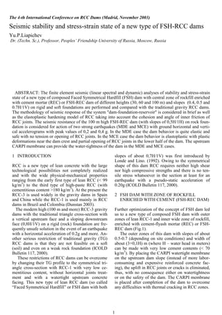
- 1. 1 1 INTRODUCTION RCC is a new type of lean concrete with the large technological possibilities not completely realized and with the wide physical-mechanical properties ranging from the early first type of lean RCC (< 99 kg/m3 ) to the third type of high-paste RCC (with cementitious content >180 kg/m3 ). At the present the RCC-3 is used widely in the gravity dams in Spain and China while the RCC-1 is used mainly in RCC dams in Brazil and Colombia (Dunstan 2003). The modern high (100 m and more) RCC-3 gravity dams with the traditional triangle cross-section with a vertical upstream face and a sloping downstream face (0,8H/1V) on a rigid (rock) foundation are fre- quently unsafe solution in the event of an earthquake with a horizontal acceleration of 0.2g and more. An- other serious restriction of traditional gravity (TG) RCC dams is that they are not feasible on a soft (soil) and even on a weak rock foundation (ICOLD Bulletin 117, 2000). These restrictions of RCC dams can be overcome by changing their TG profile to the symmetrical tri- angle cross-section with RCC-1 with very low ce- mentitious content, without horizontal joints treat- ment and with a watertight upstream concrete facing. This new type of lean RCC dam (so called “Faced Symmetrical Hardfill” or FSH dam with both slopes of about 0,7H/1V) was first introduced by Londe and Lino. (1992). Owing to the symmetrical shape of this dam RCC requires neither high shear nor high compressive strengths and there is no ten- sile stress whatsoever in the section at least for an earthquake with a pseudo-static acceleration of 0.20g (ICOLD Bulletin 117, 2000). 2 FSH DAM WITH ZONE OF ROCKFILL ENRICHED WITH CEMENT (FSH-REC DAM) Further optimization of the concept of FSH dam led us to a new type of composed FSH dam with outer zones of lean RCC-1 and inner wide zone of rockfill, enriched with cement-flyash mortar (REC) or FSH- REC dam (Fig.1). The outer zones of this dam with slopes of about 0.5-0.7 (depending on site conditions) and width of about (3+0,1H) m (where H – water head in meters) can be made with very low cement contents (< 70 kg/m3 ). By placing the CARPI watertight membrane on the upstream dam slope (instead of more labor- consuming and expensive reinforced concrete fac- ing), the uplift in RCC joints or cracks is eliminated, thus, with no consequence either on watertightness or on the safety of the dam. The CARPI membrane is placed after completion of the dam to overcome any difficulties with thermal cracking in RCC zones. The 4-th International Conference on RCC Dams (Madrid, November 2003) Seismic stability and stress-strain state of a new type of FSH-RCC dams Yu.P.Liapichev Dr. (Techn. Sc.), Professor, Peoples’ Friendship University of Russia, Moscow, Russia ABSTRACT: The finite element seismic (linear spectral and dynamic) analyses of stability and stress-strain state of a new type of composed Faced Symmetrical Hardfill (FSH) dam with central zone of rockfill enriched with cement mortar (REC) or FSH-REC dam of different heights (30, 60 and 100 m) and slopes (0.4, 0.5 and 0.7H/1V) on rigid and soft foundations are performed and compared with the traditional gravity RCC dams. The methodology of seismic response of the system "dam-foundation-reservoir" is considered in brief as well as the elastoplastic hardening model of RCC taking into account the cohesion and angle of inner friction of RCC joints. The seismic resistance of the 100 m high FSH-REC dam (with slopes of 0,5H/1H) on rock foun- dation is considered for action of two strong earthquakes (MDE and MCE) with ground horizontal and verti- cal accelerograms with peak values of 0,2 and 0,4 g. In the MDE case the dam behavior is quite elastic and safe with no tension or opening of RCC joints. In the MCE case the dam behavior is elastoplastic with plastic deformations near the dam crest and partial opening of RCC joints in the lower half of the dam. The upstream CARPI membrane can provide the water-tightness of the dam in the MDE and MCE cases.
- 2. 2 This design has been used successfully for the ver- tical upstream face of RCC dams (Miel in Colombia, Riou in France, Concepcion in Honduras, etc.). The wide central zone of the dam can be made with Figure 1. Section of the 100 m high FSH-REC dam REC (rockfill of 5-300 mm diameter, enriched with cement-flyash mortar) in the central zone of the dam can be placed in 60 cm thick layers while RCC layers in the outer zones - in 30 cm layers. Than 10- 15 cm thick cement-flyash mortar is spread over a rockfill layer and penetrates into the coarse pores of rockfill. The penetration can be facilitated by 1-2 passages of Dynapic sheep roller and subsequent compaction can be achieved by 2-3 passages of Bo- maq vibrating roller used also for compaction of RCC outer zones of the dam. The separated placing of the wide REC central zone of the FSH-REC dam permits to replace the expensive mixing plant for RCC dam with much less cheap cement mortar facility on the FSH-REC dam thus achieving the significant economical effect as well as using rockfill instead of RCC aggregates. Owing to higher rockfill layers (60 cm) than tra- ditional 30 cm of RCC and using CARPI membrane on the upstream slope instead of reinforced concrete facing the speed of construction of FSH-REC dam will be higher than homogeneous FSH dam. Naturally, construction of the FSH-REC dam as well as FSH dam should be tested on the site. But the structural (seismic) aspects of a new design of FSH-REC or FSH dam should be performed in ad- vance because at the present the required seismic (dynamic) analyses of these dams are not available. 3 PSEUDO-STATIC STABILITY OF FSH-REC AND RCC DAMS According to our stability analysis of the 60 and 100 m high FSH-REC dams during its construction the minimum cohesion of RCC of outer zones and REC should be not less than 0.5 and 0,1 MPa, corre- spondingly, to obtain the required cohesion during simultaneous placing of outer zones of RCC and central zone of REC (Liapichev 1998). This RCC cohesion value of 0,5 MPa corresponds to the mini- mum cohesion of RCC-1 joints without treatment (Schrader 1999). For RCC and REC materials the minimum inner friction angle of 450 is assumed, which corresponds to the preliminary design of RCC dams. Table 1 and 2 show the comparison, in terms of factors of safety against sliding at the foundation, of a 100 m high traditional RCC dam with vertical up- stream and sloping downstream faces (Sd=0.7; 0.8 and 0.9) and an FSH-REC dam of the same height and both slopes (Su=Sd=0.4; 0.5 and 0.7). Three types of foundations were considered: tra- ditional rock foundation (with the angle of inner friction =450 ), alluvial (=350 ) and moraine (=300 and cohesion C=0,1MPa) foundations. Two operation cases were considered: static case with a maximum reservoir level and seismic (pseudo static) case with a ground acceleration of 0.2g. In seismic case the shear wedge method was used for the calculation of accelerations distribution in both dam because this method corresponds to the actual shear movements of RCC dams during earthquakes. For both dams the uplift was taken at 40% of the force developed by a straight percolation line from full reservoir head upstream to no head at the dam. Table 1. Factors of safety against sliding for 100 m high RCC dam Types of foundation Factors of safety for downstream slope (static/seismic cases) 0.7 0.8 0.9 Rock 1.91/1.47 2.14/1.60 2.37/1.73 Alluvium 1.33/1.02 1.50/1.12 1.66/1.21 Moraine 1.24/0.95 1.39/1.04 1.54/1.13 2x0.3=0.6m 2x0.3=0.6m Detail A 0.4 2x0.3=0.6m CARPI membrane 2x0.3=0.6m 1 0.4 RCC-1 1 REC Detail B 0.5 1 REC RCC-1 REC REC REC Grout curtain Gallery CVC Detail A 1 0.5 1CARPI membrane RCC 1 0.4 Detail B 0.5 1 0.4 0.5 1 dam axis 100.00 0.00 RCC
- 3. 3 Table 2. Factors of safety against sliding for 100 m high FSH- REC dam. Types of foundation Factors of safety for both slopes (stat- ic/seismic cases) 0.4 0.5 0.7 Rock 2.59/1.91 3.15/2.21 4.27/2.74 Alluvium 1.99/1.33 2.20/1.55 2.98/1.92 Moraine 1.65/1.22 2.01/1.41 2.73/1.75 According to Russian design norms for gravity dams (1987) the minimum allowable factors of safe- ty against sliding on the contact dam-rock founda- tion for static and seismic cases are, corresponding- ly, 1.32 and 1.18. It means that RCC or PG (gravity dam of conventional concrete) dams aren’t feasible on soft foundation (alluvium, moraine, etc.). On the contrary, FSH-REC or FSH dams even with steep slopes (0.4H/1V) are quite feasible and safe on rock and soft foundations. Table 3 and 4 show the comparison, in terms of normal and principal stresses at the dam base for static and seismic (pseudo-static with a ground ac- celeration of 0.2 g) cases of both dams of the same height (100 m) on a rock foundation. Table 3. Stresses at the base of 100 high RCC dam. Stresses in MPa for downstream slope (seismic case) Stresses 0.9 0.8 0.7 σy u -0.74 -0.42 0.3 σx u -1 -1 -1 τxy u 0 0 0 σ1 u -0.74 -0.42 0.3 σ3 u -1 -1 -1 σy d -1.67 -2.00 -2.48 σx d -1.67 -1.28 -1.21 τxy d 1.50 1.60 1.73 σ1 d 0 0 0 σ3 d -3.03 -3.29 -3.69 The upper index u in all stresses in tables 3 and 4 denotes upstream face, d – downstream face. The sign (-) denotes compression and (+) – tension. Table 3 shows that the M. Lévy condition is not satisfied at the RCC dam heel (with the downstream slope of 0.7) and the base joint is likely to open. The same is true for the 100 m high FSH-REC dam with both slopes of 0.4V/1H. But for the same dam with both slopes of 0.5V/1H and flatter the RCC base joints are likely to be closed after even a strong earthquake. Table 4. Stresses at the base of the 100 m high FSH-REC dam. Stresses in MPa for both slopes (static/seismic cases) Stresses 0.7 0.5 0.4 σy u -1.30/-0.94 -0.90/-0.39 -0.48/0.17 σx u -1.14/-0.97 -0.97/-0.47 -0.91/-0.82 τxy u -0.21/0.03 0.04/-0.30 0.20/0.47 σ1 u -1.45/-0.91 -0.88/-0.23 -0.39/0.36 σ3 u -1/-1 -1/-1 -1/-1 σy d -1.54/-1.90 -1.95/-2.27 -2.39/-3.0 σx d -0.75/-0.93 -0.48/-0.61 -0.38/-0.48 τxy d 1.08/1.30 0.97/1.23 0.95/1.22 σ1 d 0/0 0/0 0/0 σ3 d -2.29/-2.80 -2.44/-3.09 -2.77/-3.50 The same static and seismic (pseudo-static) stabil- ity and stress analyses were performed for the 30 and 60 m high FSH-REC dams on the same founda- tions. These analyses showed that these FSH-REC dams with both slopes of 0.4V/1H or flatter are quite stable and safe on rock and soft foundations even for action of very strong earthquake with a ground ac- celeration of 0.4g. In the 30 m high FSH-REC dam the enrichment of rockfill with cement mortar can be excluded, thus, creating the composite FSH-RF dam. 4 SEISMIC (PSEUDO-DYNAMIC) STRESS- STRAIN STATE ANALYSIS OF FSH-REC DAMS The finite element seismic (linear spectral or pseu- do-dynamic) analyses of stress-strain state of the FSH-REC dams of different heights (30, 60 and 100 m) and slopes (0,4; 0,5 and 0,7) on rock (rigid) foundations were performed for action of a ground acceleration of 0,20g. The main results of the seis- mic analysis for the 100 m high FSH-REC dam with slopes of 0.5 V/1H are shown on Fig. 2-5. Fig. 2 shows that the M. Lévy condition is satis- fied at the dam heel and the base RCC joints are closed. The distribution of maximum principal stresses 1 in the dam (Fig. 3) is nearly uniform from upstream to downstream faces reaching only 2.3 MPa at the toe. The same uniform distribution was obtained for shear normal and maximum stresses with maximum values, correspondingly, 0.7 and 0.9 MPa in RCC outer zones at the dam base (Fig. 4, 5).
- 4. 4 Figure 2. Vertical normal stresses y (t/m2 ) in the 100 m high FSH-REC dam with both slopes of 0.5V/1H (seismic case). Figure 3. Maximum principal stresses 1(t/m2 ) in the 100 m high FSH-REC dam with both slopes of 0.5V/1H (seismic case). Figure 4. Shear normal stresses xy (t/m2 ) in the 100 m high FSH-REC dam with both slopes of 0.5V/1H (seismic case). Figure 5. Maximum shear stresses max (t/m2 ) in the 100 m high FSH-REC dam with both slopes of 0.5V/1H (seismic case). Thus, the stress-strain state of the 100 m high FSH- REC dam with both slopes of 0.5V/1H for action of a strong earthquake is much more favorable and safe than in the 100 m high traditional RCC or PG dam with the downstream slope of 0.8V/1H. 5 SEISMIC (DYNAMIC) STRESS-STRAIN STATE ANALYSIS OF HIGH FSH-REC DAM According to the new Russian anti-seismic design norms for dams (2003) the seismic (dynamic) analy- sis are to be performed for high dams (100 m and higher) located in moderate or high seismic regions. The dynamic analysis of the 100 m high FSH- REC dam with slopes of 0.5V/1H was performed by the method used now in the Geodynamic Center of Hydroproject Institute (Bronchtein et al. 2002). The dynamic response of the ‘dam-foundation- reservoir’ system for action of these accelerations was considered in the analysis. The influence of gravity waves in the reservoir was neglected and the boundary conditions between reservoir and dam and reservoir and foundation were simplified. The condi- tion of equal normal displacements on these bounda- ries was assumed for dam, foundation and reservoir. The passing of shear stresses through these bounda- ries was assumed that allows simplify the problem by abandoning the interface elements (Groshev 2000). As for a mathematic model of RCC and REC the elastoplastic hardening model with associated flow rule and shear strength of RCC joints (angle of the inner friction and cohesion C) was used (Fig.6). The hardening parameters of the model are shear and volume plastic deformations on the maxi- mum shear plane (Groshev, Shablinsky 1991). This RCC model simulates well cracking or open- ing of RCC horizontal joints and their subsequent reaction only to compression. -11.39 85.43 194.35 212.09 156.22 176.33 -3.24 74.73 137.61 202.50 113.80 165.49 6.41 63.39 118.39 167.38 99.44 160.39 12.34 54.90 99.42 131.40 86.91 150.77 15.81 47.10 79.75 99.46 74.12135.52 16.1338.6860.7572.91 61.13113.44 13.1529.5744.0750.7347.3386.18 6.7621.2928.1730.8432.8754.83 -2.0311.3110.1513.1417.3119.66 -11.39 -11.39 85.43 194.35 212.09 156.22 176.33 176.33 176.33-3.24 -3.24 165.49 165.496.41 6.41 160.39 160.3912.34 12.34 150.77 150.7715.81 15.81 135.52 135.5216.13 16.13 113.44 113.4413.15 13.15 86.18 86.186.76 6.76 54.83 54.83-2.03 -2.03-2.0311.3110.1513.1417.31 19.66 19.66 95.37 132.99 218.64 224.05 179.63 210.45 101.30 129.18 160.88 220.84 124.01 194.04 93.09 107.13 144.73 184.95 109.02 187.93 81.03 94.19 123.61 146.49 98.43 179.22 71.96 79.08 99.88 113.72 89.16164.21 60.4564.4277.8287.63 79.29139.82 49.3150.8559.2866.2764.70106.56 31.7238.2841.3441.4445.9071.90 22.1324.5922.6225.4025.8128.02 95.37 95.37 132.99 218.64 224.05 179.63 210.45 210.45 210.45101.30 101.30 194.04 194.0493.09 93.09 187.93 187.9381.03 81.03 179.22 179.2271.96 71.96 164.21 164.2160.45 60.45 139.82 139.8249.31 49.31 106.56 106.5631.72 31.72 71.90 71.9022.13 22.1322.1324.5922.6225.4025.81 28.02 28.02 -82.67 -64.93 -61.42 -43.13 -53.04 -73.68 -56.95 -64.77 -53.73 -57.60 -31.25 -66.76 -51.12 -51.38 -52.04 -51.54 -29.15 -65.04 -39.54 -43.15 -45.86 -42.29 -30.03 -64.16 -30.15 -33.43 -36.44 -35.28 -31.47-60.94 -21.70-24.21-27.44-29.52 -30.91-53.19 -16.25-17.27-20.38-23.98-25.92-40.28 -7.53-13.19-14.91-15.27-18.52-30.28 -6.61-8.43-8.37-10.04-9.31-12.43 -82.67 -82.67 -64.93 -61.42 -43.13 -53.04 -73.68 -73.68 -73.68-56.95 -56.95 -66.76 -66.76-51.12 -51.12 -65.04 -65.04-39.54 -39.54 -64.16 -64.16-30.15 -30.15 -60.94 -60.94-21.70 -21.70 -53.19 -53.19-16.25 -16.25 -40.28 -40.28-7.53 -7.53 -30.28 -30.28-6.61 -6.61-6.61-8.43-8.37-10.04-9.31 -12.43 -12.43 85.39 68.09 89.81 83.77 71.79 96.60 67.78 65.75 74.00 99.62 52.94 92.35 58.42 52.05 64.58 84.39 49.12 90.57 45.72 43.33 55.56 66.84 44.89 86.57 36.17 33.47 43.05 50.76 40.4679.07 27.4724.2530.5836.96 35.4066.81 21.7317.6521.2626.2728.0350.00 13.6113.6215.0316.3019.6835.39 12.989.319.0510.249.3513.43 85.39 85.39 68.09 89.81 83.77 71.79 96.60 96.60 96.6067.78 67.78 92.35 92.3558.42 58.42 90.57 90.5745.72 45.72 86.57 86.5736.17 36.17 79.07 79.0727.47 27.47 66.81 66.8121.73 21.73 50.00 50.0013.61 13.61 35.39 35.3912.98 12.9812.989.319.0510.249.35 13.43 13.43
- 5. 5 Figure 6. Elastoplastic hardening model of RCC. The synthetic horizontal and vertical accelera- tions with peak values of 0,8g were normalized as the Maximum Design Earthquake (MDE) with the peak ground horizontal and vertical accelerations of 0.2 and 0.14g, correspondingly (Fig.7-a, b) and as the Maximum Credible Earthquake (MCE) with the peak ground horizontal and vertical accelerations of 0.4 and 0.28g. (a) (b) Figure 7-a, b. Ground horizontal (a) and vertical (b) accelera- tions (in m/s2 ) for the MDE. The same shear strength values of RCC-1 and REC joints were adopted in this dynamic analysis as in the previous linear spectral analysis: in RCC-1 joints φ=450 , C=0,5 MPa, in REC joints φ=450 , C=0,1 MPa. Elasticity modulus of RCC-1 E=5000 MPa and REC E=1000 MPa, Poison coefficient of RCC-1 υ=0.2 and REC υ=0.25. Elasticity modulus of rock foundation E=10000 MPa and υ=0.2. The results of dynamical analysis of the 100 m high FSH-REC dam with slopes of 0.5V/1H for ac- tion of MDE are presented on Figs. 8 and 9. Fig. 8 shows the variation of the horizontal dis- placements of six control points along the upstream slope: the first one is at the base and the sixth is at the crest (with 20m vertical spacing between points). As can be seen from Fig. 8, the dynamic response of dam is elastic and elastic horizontal displacement are completely damping by the end of the MDE without any residual values. The maximum horizontal accel- eration at the dam crest for the MDE reaches 0.31g. Fig. 9 shows the finite element mesh of the dam and rock foundation with only one crack or joint opening in RCC-1 zone near the dam base during the MDE. But after the MDE the RCC joint is closed. Figure 8. Variation of horizontal displacements of six points on the upstream slope for the MDE. Figure 9. Finite element mesh and one crack (joint) opening in RCC near the dam base for the MDE.
- 6. 6 Thus, it is clear that the FSH-REC dam is safe for the MDE case, and that there is no development of tensile stresses or opening of RCC-1 joints. The results of dynamical analysis of the same FSH-REC dam for action of MCE with the ground peak horizontal and vertical accelerations of 0.4 and 0.28g are presented on Figs. 10, 11 and 12. Fig. 10 shows the variation of the horizontal dis- placements of six control points along the upstream slope from the dam base up to its crest. As can be seen from Fig. 10, the dynamic response of the dam is elastic and elastic horizontal displacement are, mainly, damping by the end of the MDE without re- sidual (plastic) values except the point 6 at the dam crest. Therefore, the maximum horizontal accelera- tion at the dam crest for the MCE reaches only 0.28g (Fig. 11) comparing to 0.31g in the MDE case. The cracking pattern (Fig. 12) in the dam body for the MCE case is deteriorated comparing to the MDE: in the lower part of the dam the cracks (joints opening) propagated from the upstream slope to- wards the dam axis. However, owing to the up- stream impervious CARPI membrane, the uplift propagation through RCC and RSC joints is impos- sible and seismic safety of the dam is provided. Figure 10. Variation of horizontal displacements of six points on the upstream dam slope for the MCE. Figure 11. Variation of horizontal accelerations (g) of six points on the upstream dam slope for the MCE. Figure 12. The cracking (joints opening) pattern in the dam body for the MCE. The cracking or joints opening in the RCC outer zones during the MCE can be excluded or, at least, decreased by joints treatment in these zones (bed- ding mix) that can increase twice or more RCC joint cohesion. In this case another solution is remained: to decrease the steepness of both slopes from 0.5 to 0.6 thus excluding any treatment of the RCC joints.
- 7. 7 The hypothetic maximum earthquake (HME) with the peak ground horizontal and vertical accelerations of 0.8 and 0.56g, correspondingly, (twice as much as the MCE) was applied to the dam to achieve its complete cracking (joints opening) or hypothetic failure. Figure 13. Variation of horizontal displacements of six points on the upstream dam slope for the hypothetic maximum earth- quake. Fig. 13 shows the variation of the horizontal dis- placements of six control points along the upstream slope from the dam base up to its crest. As can be seen from Fig. 13, the dynamic response of the dam is complex: at the dam crest (point 6) the residual (plastic) horizontal displacements are developed af- ter the earthquake while in the major rest part of the dam (points 1-5) only the elastic displacements are developed. The maximum horizontal acceleration at the dam crest for this HME case reaches 0.38g com- paring to 0.28g in the MCE case. In this hypothetic case the horizontal cracks or all horizontal joints in the dam body from the upstream to downstream faces are opened after the HME. Thus, the 100 m high FSH-REC dam with both slopes of 0.5H/1V has, at least, the double seismic (dynamic) margin against action of the MCE. 6 CONCLUSIONS It is shown that a new type of composite FSH dam with the outer zones of lean RCC and inner wide zone of rockfill enriched with cement mortar (FSH- REC dam) of height up to 100 m on rock or soil foundation is a very attractive alternative comparing to traditional RCC or PG dams. The seismic (dy- namic) analysis of the 100 m high FSH-REC dam with both slopes of 0.5H/1V has shown the excellent behavior of its symmetrical cross-section for action of very strong earthquake with peak ground horizon- tal and vertical accelerations, correspondingly, of 0,40 and 0.28g. Owing to the CARPI impervious membrane placed on the upstream slope there are no uplift in the lean RCC joints of the dam even for ac- tion of the hypothetic maximum earthquake with a peak ground acceleration of 0.80g. The possible technological problems of construc- tion of the FSH-REC dam as well as FSH dam can be checked and solved in advance during construc- tion of the FSH-REC cofferdam on the site. REFERENCES Bronshtein, V.I., Groshev, M.E., Savich, A.I. 2002. Seismic safety in hydro power sector of Russia. HydroVision 2002.Technical paper 052. HCI Publication. USA. Groshev, M.E. 1998. Methods and computer programs for seismic safety assessment of hydropower plants and dams. Proc. Safety of Energy Structures (in Russian). Publ. NIIES, Moscow, Issue 7: 130-139. Groshev, M.E., Shablisky G.E. 1991. Application of the theory of plastic flow for simulation of deformations and strength of concrete. Civil Engineering and Architecture (in Rus- sian). Moscow. Dunstan, M.R.H. 2003. RCC dams (under construction and completed) in 2003. Hydropower and Dams. World Atlas and Industry Guide. ICOLD Bulletin 117, 2000. The gravity dam – a dam for the future. Review and recommendations. Liapichev, Yu. P. 1998. New structures of dam from RCC and rockfill. Problems of theory and practice in engineering re- search (in Russian). Proc. Structural Mechanics. Publ. As- sociation of Civil Engineering Institutes. Moscow. 39-43. Liapichev, Yu. P. 1998. RCC dams and composite RCC and rockfill dams. Aspects of design, construction and safety (in Spanish). Seminar for ESAGEN, Medellin, Colombia. Londe, P., Lino, M. 1992. The faced symmetrical hardfill dam: a new concept for RCC. Water Power and Dam Construc- tion, Vol. 44, Number 2. Schrader, E.K. 1999. Shear strength and lift joint quality of RCC. Hydropower and Dams, Vol. 6, Issue 1: 46-55.