Download to read offline
![International Journal of Science, Engineering and Technology Research (IJSETR), Volume 4, Issue 12, December 2015
4320
ISSN: 2278 – 7798 All Rights Reserved © 2015 IJSETR
Solar Panel Condition Monitoring System based on
Wireless Sensor Network
Abhishek Parikh, Farah Pathan, Bhavdipsinh Rathod, Sandeep Shah
Abstract - Continuousmonitoring the condition and
detecting the faults to ensure the stable power delivery of
Solar panel in remote area is our contribution in this
paper, this work is part of project. I am working on this
project at Optimized Solutions Pvt. Ltd. as a part of
curriculum activity in my final year project at Maharaja
Sayajirao University. This paper describes the hardware
and software implementation for fault detection and
continuous monitoring system for solar panel in remote
area. This research problem has been stated by engineers
working in Solar panel maintenance system. As proposed
solution to this wireless sensor node is provided with
Voltage sensor, Current sensor, Light sensor,
Temperature sensor and Dust sensor and XBeeS2 to
implement WSN. Data are being continuously stored and
monitored at central station called HUB and through that
data are being sent to server via Ethernet. A friendly GUI
using Python is implemented to visualize monitoring
process and save data on Excel file. The designed system
is built and satisfactory results has been obtained.
Keywords - Solar panel, MSP430 micro-controller, Solar
panel, fault-detection, Remote monitoring, XBee, Python,
Wireless Sensor networks.
I. INTRODUCTION
As non-renewable energy resources are depleted with
time it is necessary to use renewable energy resources like
Solar and Wind energy because of its unlimited supply,
monetary long-term benefits and environmental friendliness.
According to DJ Pandian, principal secretary, energy and
petrochemicals department of the state government, they
expect around 300 MW of solar power generation capacity to
be commissioned in the state before 31st
December 2015.
The growth of solar photo-voltaic products in consumer
market shows awareness of renewable energy. In order to get
maximum benefit and efficiency and to prevent damage it is
necessary to monitor the condition of photovoltaic panels
continuously[1][2][5].
Though there is very low probability of electrical fault
of individual component or total failure of system it is
indispensable to monitor and notify the center station to
prevent from damage as the cost of components are very
much high. Natural cause like lightning strikes, storm,
snowfall and heavy rain or even a insect can also damage
solar panel and overloading in supply grid can also force
power reduction and some times shutdowns also. So it is
necessary to monitor each and every smallest fault and report
it to central station quickly otherwise it leads to large
financial losses. Also it is require to acquire losses due to
condition of solar panel. High temperature and dust causes
significant power loss and reduce the over all efficiency of
Solar panel.
In present industrial scenario PLC and SCADA system
are being used to monitor Voltage and Current of Solar panel
plant. In this type of monitoring system all the panels are
combined and the monitoring system is placed after the
inverter. Problem with this type of monitoring system is we
can not get each solar panel Voltage and Current of
individual solar panel and also we can’t detect fault or
measure condition of solar panel. PLC system is very much
costlier also and once it is wired it is static. So to overcome
this problems and as a better alternative solution to this we
provide wireless solar panel condition monitoring system
that measures electrical parameters of all of the solar panel
individually and also it monitors the condition of solar panel
continuously. This micro-controller based system is also
cost-effective as it dose not requires any extra sensor circuits
for voltage and current, also the end node is powered by
solar panel so it is versatile solution.
II. PROJECT ARCHITECTURE
For electrical parameter measurement of all the panels it
is difficult for engineer to measure them on the field so
wireless sensor network is a solution to this.
The Project system architecture divided into two major
parts. The first part is wireless sensor node [4] which is
connected to each individual solar panel and second part is
central computer or HUB which is a computer is connected
wirelessly with all devices that displays the data of all panels
using GUI [3]. The XBee module connected to node must be
in end device or router mode configuration where as the
HUB should be in Coordinator mode[12]. Coordinator asks
each node to transfer their data and that device responds with
acquired data. As that data received by HUB it stores it
internally on excel file and forward the data to cloud via
internet.
A. Data Acquisition Node
The data acquisition node is made by several sensors
that are Voltage sensor, Current sensor, Light sensor, Dust
sensor and Temperature sensor. MSP430f6779 micro-
controller has seven channel on chip SD-24 bit ADC and 6
channel 10- bit ADC. So at a time three solar panel data can
be monitored with it. . So as shown in figure-2 All the
sensors are connected to 10 bit ADC and Voltage and Current
front-end sensor are connected to Sigma-Delta ADC. Rather
than using this type of expensive Voltage and Current sensors
to reduce cost We have used simple resistor divider circuit.
This circuit vary from panel to panel but it’s cost reduce to](https://image.slidesharecdn.com/ijsetr-vol-4-issue-12-4320-4324-160111064002/75/Ijsetr-vol-4-issue-12-4320-4324-1-2048.jpg)
![International Journal of Science, Engineering and Technology Research (IJSETR), Volume 4, Issue 12, December 2015
4321
ISSN: 2278 – 7798 All Rights Reserved © 2015 IJSETR
fiftieth part of cost of sensor so that Voltage and Current
front-end circuit used instead of separate sensors.
Fig. 1. Project Architecture
At my node design side I will be having three
Voltage and three Current front-end circuit to measure
electrical parameter. As we get DC Voltage and Current
for each panel we can get power that is being consumed
by load. MSP430f6779 has on chip RTC so we can get
real time data through it[11].
As a power supply of our board we have used
Auxiliary power supply which is taken from solar panel
itself so my device becomes self powered. Also
temperature sensor, light sensor and dust sensor are also
powered by solar panel itself so there is no need to supply
the power from any other device to node. Now converted
data from 10 bit ADC is merged with SD-24 bit ADC and
it is combined with current date-time one frame of XBee
S2 is made and that frame is sent to UART serially. Our
UART baud rate is 9600bps we can make it to higher data
rate also. XBee is connected to node via UART
communication protocol. We have to set Zigbee
communication protocol and than only we can send a data
to central station. Transmit frame structure of XBee s2 is
shown in figure 3[12]. XBee module works on mesh
protocol.
XBee module ensures the data received by central
station by receiving acknowledge frame. The node
continuously monitors the sensors and electrical
parameters of all solar panels but it does not send it until
the HUB asks it for. When HUB asks it to send its
Fig. 2. Node Design
parameters it sends its frame which include data of
sensors and panel parameters and current time. We need to
attach external coin cell battery with RTC module to keep
it on while solar panel is off.
B. Wireless Sensor Network
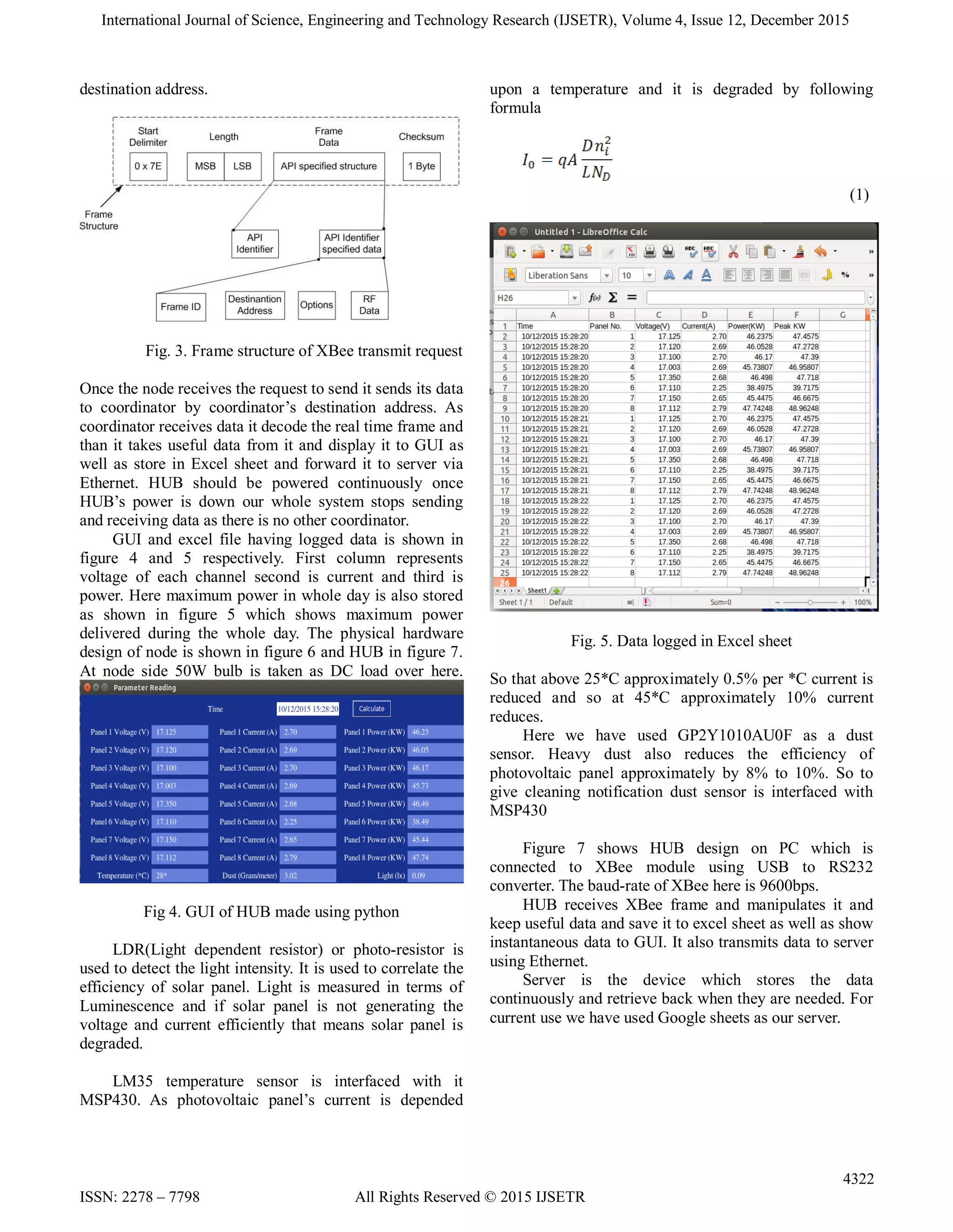
The frame structure of XBee transmit request frame
is shown in figure. Here, RF data contains all the data of
node including electrical parameters, sensor data and time
also. Option filed contains whether to receive
acknowledgment or not. Destination address contains 64
bit of destination physical address which is identical to all
other XBee modules. No other XBee can have same
physical address. Because of This field of XBee we can
ensure that no other nearby device can interfere in our
communication. If more than one frame is being sent to
other device frame id is provided with it. API identifier
specify type of frame. Length specifies the length of our
data. If length is lower than 0xFFh value it is stored in
LSB only and if more than it MSB and LSB both are used
to specifies length of upcoming data. Start delimiter
specifies next frame is coming and check-sum is 2’s
complement of addition of all above fields. XBee module
won’t send imperfect frames. Any of fields is not
matching though data is coming to its UART pins but
because of wrong data it discards frame by itself.
C. HUB Design
HUB is nothing but a Zigbee to Ethernet gateway
with GUI. In HUB design application is made on high
level python language. GUI and back-end process flow
both are made on python. In which XBee S2 coordinator
is connected to HUB or central CPU which asks each and
every node one by one to send their data by theirs](https://image.slidesharecdn.com/ijsetr-vol-4-issue-12-4320-4324-160111064002/75/Ijsetr-vol-4-issue-12-4320-4324-2-2048.jpg)
![International Journal of Science, Engineering and Technology Research (IJSETR), Volume 4, Issue 12, December 2015
4323
ISSN: 2278 – 7798 All Rights Reserved © 2015 IJSETR
Fig. 6. Hardware design of Node
.
Fig. 7. Design of HUB
III. CONCLUSION
In this work we have studied how to access a set of
solar panel at remote area with using WSN. Continuous
monitoring solar plant is prime requirement of industry.
Specified hardware and software is been made for the
continuous monitoring purpose. In the prospective work
the better GUI design and to make better human machine
interface. Also there will be some difficulties in real
environment when there is more then hundreds of PV
panels.
Fig. 8. WSN System Architecture
IV. ACKNOWLEDGMENT
Sincere gratitude to Optimized Solutions Pvt. Ltd. for
providing me a useful guidance and to provide resources.
I am thankful to Bhavdip sir, Sandeep sir and Farah mam
for providing me insight as well as guidance to this
project.
V. REFERENCES
[1] Farihah Shariff, Nasrudin Abd Rahim, Hew Wooi
Ping “Photovoltaic Remote Monitoring System](https://image.slidesharecdn.com/ijsetr-vol-4-issue-12-4320-4324-160111064002/75/Ijsetr-vol-4-issue-12-4320-4324-4-2048.jpg)
![International Journal of Science, Engineering and Technology Research (IJSETR), Volume 4, Issue 12, December 2015
4324
ISSN: 2278 – 7798 All Rights Reserved © 2015 IJSETR
Based on GSM”,IEEE Conference on Clean Energy
and Technology (CEAT), pp. 379-382, November
2013.
[2] C. Ranhotigamage, and S. C. Mukhopadhyay, “Field
trials and performance monitoring of distributed
solar panels using a low-cost wireless sensor network
for domestic application,” IEEE Sensors Journal,
vol. 11, pp. 2583-2590, October 2011.
[3] Ali Al-Dahoud, Mohamed Fezari, Thamer A. Al-
Rawashdeh, Ismail Jannoud, “Improving Monitoring
and Fault Detection of Solar Panels Using Arduino
Mega in WSN”,London United Kingdom 13 (3) Part
VII, March 14-15.
[4] Ponmozhi.G, Mr.L.Bala kumar, “Embedded System
Based Remote Monitoring and Controlling Systems
for Renewable Energy Source”, International
Journal of Advanced Research in Electrical,
Electronics and Instrumentation Engineering Vol. 3
,April 2014.
[5] Mohamed Fezari, Fatma Zohra Belhouchet, Ali Al-
Dahoud, “Remote Monitoring System using WSN
for Solar Power Panels”, First International
Conference on Systems Informatics, Modelling and
Simulation, 2014.
[6] Se-Kang Ho ; Wei-Jen Lee ; Chia-Chi Chu ; Ching-
Tsa Pan, “An internet based embedded network
monitoring system for renewable energy systems”,
ICPE '07 , 2007.
[7] Jian-ming Jiang,” The Electrical Ethernet monitoring
system based on Embedded Web server” 2010
IEEEvolume3.
[8] Fang Hongping,” The Design of Remote Embedded
Monitoring System based on Internet”
IEEEMeasuring Technology and Mechatronics
Automation (ICMTMA), 2010.
[9] David Curren, “A survey of simulation in sensor
networks,”University of Binghamton, NY, 2005.
[10] Dimosthenis Pediaditakis et Al. “ Performance and
ScalabilityEvaluation of the Castalia Wireless Sensor
Network Simulator”, in international conférence
SIMUTools 2010, March 15-19 2010, Torremolinos,
Malaga, Spain, 2010.
[11] MSP430f6779 Datasheet, Texas Instruments
http://www.ti.com/lit/ds/symlink/msp430f6779.pdf.
[12] XBee S2 Datasheet Digi-International
http://www.farnell.com/datasheets/27606.pdf.
[13] G.J. Zhang, “Forest fire detection system based on
Zigbee wireless sensor network,” Journal of Beijing
Forestry University, pp. 122-124, October 2008.
[14] H. Liu, “Development of farmland soil moisture and
temperature monitoring system based on wireless
sensor network”, Journal of Jilin University
(Engineering and Technology Edition), pp. 604-608,
March 2008.
[15] J. Xiao et al., “Design of pv power station
remotemonitoring system data acquisition device,”
Proceedings of the 2011 International Conference on
Advanced Mechatronic Systems, Zhengzhou, China, pp.
367-372, August 2011.
A. Parikh received B.E.(Electronics and Communication)
from GTU University Ahmedabad in 2014 and pursuing
M.E.(Microprocessor System and Application) from
MSU University Baroda. His field of interest includes
Internet of things, Power engineering, photovoltaic
systems.
F. Pathan received B.Tech(Electronics) and
M.E.((Microprocessor System and Application) from
MSU University Baroda. She is pursuing her Ph.D. In
wireless communication. She has two years of experience
in teaching in Electrical Engg. Dept. In FTE, MSU
Baroda. She had published paper on WSN in international
journal. Her field of interest is Wireless sensor networks
and digital signal processing.
B. Rathod received diploma(Electronics and
Communication) in 2007 from TEB Gandhinagar and
B.E.(Electronics and Communication) in 2010. He has 5
years experience in Industry. Currently he is working as
product development manager in Optimized Solutions
Pvt. Ltd. Ahmedabad. His area of interest is Harmonics
analysis of Power supply, Smart metering applications
S. Shah received his B.E.(Instrumentation and Control)
from GU in 2001 and PGDM from IIM Calcutta. He is
currently He is working as managing director of
Optimized Solutions Pvt. Ltd. Ahmedabad. His area of
interest is Energy measurement services, Data acquisition
systems.](https://image.slidesharecdn.com/ijsetr-vol-4-issue-12-4320-4324-160111064002/75/Ijsetr-vol-4-issue-12-4320-4324-5-2048.jpg)

This document describes a wireless sensor network system for remotely monitoring solar panels. Sensor nodes attached to each solar panel measure electrical parameters like voltage, current, light intensity, temperature, and dust. The nodes send this data via XBee modules to a central HUB computer. The HUB displays the data in real-time using a Python GUI and stores it in an Excel file. It also forwards the data to a server via Ethernet. This system allows continuous monitoring of each individual solar panel's performance and condition from a remote location.


![[DSC Europe 25] Uros Pesic - The Reality of AI in Marketing.pdf](https://cdn.slidesharecdn.com/ss_thumbnails/rtkodnmtycovsllvzsyn-9-251215095918-b0c6bfe3-thumbnail.jpg?width=640&height=640&fit=bounds)
![[DSC Europe 25] Debmalya Biswas - Agentification: the art of transforming man...](https://cdn.slidesharecdn.com/ss_thumbnails/r5azlggvtqiaiiusrqdr-4-251212103249-5a12c89b-thumbnail.jpg?width=640&height=640&fit=bounds)

![[DSC Europe 25] Dunja Adzic Jovanovic - AI and Cybersecurity: Defending Data ...](https://cdn.slidesharecdn.com/ss_thumbnails/o1zylpbhrtwnixxq2xj8-7-251211083048-185086f6-thumbnail.jpg?width=640&height=640&fit=bounds)

![[DSC Europe 25] Branko Dzakula - From Defense to Attack: How AI Redefines Cyb...](https://cdn.slidesharecdn.com/ss_thumbnails/80bdzdxpr3ky2g0qvyk9-8-251211083048-ce5fc1ee-thumbnail.jpg?width=640&height=640&fit=bounds)


![[DSC Europe 25] Dusan Nesic - Securing Tomorrow’s Infrastructure: Why Cyber-P...](https://cdn.slidesharecdn.com/ss_thumbnails/qikbszfftyowjm2q6duw-1-251211083848-8f2ead6b-thumbnail.jpg?width=640&height=640&fit=bounds)


![[DSC Europe 25] Jovan Bogicevic - Legacy to AI-Driven Defense: Transforming D...](https://cdn.slidesharecdn.com/ss_thumbnails/rsarluadt563hntyfc8q-3-251211083849-3e7bc4c0-thumbnail.jpg?width=640&height=640&fit=bounds)

![[DSC Europe 25] Tatevik Maytesyan - How to actually use AI in marketing: gett...](https://cdn.slidesharecdn.com/ss_thumbnails/tjo626lsqdgfntbgl2mw-4-251216103155-e36cd239-thumbnail.jpg?width=640&height=640&fit=bounds)
![[DSC Europe 25] Branko Urosevic -Rethinking Financial Talent: Integrating Cod...](https://cdn.slidesharecdn.com/ss_thumbnails/8jjrus8ttko6qj64f58f-3-251212103250-642c6374-thumbnail.jpg?width=640&height=640&fit=bounds)