This document provides specifications and operating instructions for two oscilloscope models: a 20MHz model and a 15MHz model. It includes details on their vertical deflection systems, triggering systems, horizontal sweep systems, X-Y mode functions, and CRT specifications. The document also provides diagrams of the front and rear panels showing the various control buttons and terminals. It describes the functions of each control button for settings like deflection factor, coupling mode, sweep rate, trigger level, and more.
Digital timer switches are utilized to control the task of electrical gadgets dependent on a customized timetable. This undertaking portrays a programmable digital timer dependent on the PIC16F628A microcontroller that can be customized to plan the on and off activity of an electrical apparatus. The apparatus is controlled through a hand-off switch. This clock change enables you to set both on and off time. That implies, you can program when would you like to turn the gadget on and for to what extent you need it to be stayed on. The greatest time interim that you can set for on and off activity is 99 hours and 59 minutes. The task gives an intuitive UI utilizing a 16×2 character LCD alongside 4 push catches.
K factor >1 does not ensure unconditional stability !Stephane Dellier
K factor is not a stability test and is often incorrectly applied by the designers. This application note explains the differences between K factor and pole-zero identification and how efficiently use both of them.
Get Programmable digital timer | Programmable timer switch | Cyclic Timer- GI...PrasadPurohit1988
GIC Manufactures a variety of Industrial Electronic Timer Switches, Synchronous Timers, Cyclic Timers, Digital Timers, Programmable Timer Switches, and programmable timers at an affordable cost. http://gicindia.com/products/timers.html
Mitsubishi electric intrument transformers dienhathe.orgDien Ha The
Khoa Học - Kỹ Thuật & Giải Trí: http://phongvan.org
Tài Liệu Khoa Học Kỹ Thuật: http://tailieukythuat.info
Thiết bị Điện Công Nghiệp - Điện Hạ Thế: http://dienhathe.vn
Mitsubishi electric intrument transformers dienhathe.orgDien Ha The
Khoa Học - Kỹ Thuật & Giải Trí: http://phongvan.org
Tài Liệu Khoa Học Kỹ Thuật: http://tailieukythuat.info
Thiết bị Điện Công Nghiệp - Điện Hạ Thế: http://dienhathe.vn
Mikro,
Catalog Thiết Bị Điện Mikro, Catalog Thiết Bị Điện,
Catalog Phụ Kiện Mikro, Catalog Phụ Kiện,
Catalog Mikro, Catalog,
http://dienhathe.com,
Chi tiết các sản phẩm khác của Mikro tại https://dienhathe.com
Xem thêm các Catalog khác của Mikro tại https://dienhathe.info
Để nhận báo giá sản phẩm Mikro vui lòng gọi: 0907.764.966
DevOps and Testing slides at DASA ConnectKari Kakkonen
My and Rik Marselis slides at 30.5.2024 DASA Connect conference. We discuss about what is testing, then what is agile testing and finally what is Testing in DevOps. Finally we had lovely workshop with the participants trying to find out different ways to think about quality and testing in different parts of the DevOps infinity loop.
GraphRAG is All You need? LLM & Knowledge GraphGuy Korland
Guy Korland, CEO and Co-founder of FalkorDB, will review two articles on the integration of language models with knowledge graphs.
1. Unifying Large Language Models and Knowledge Graphs: A Roadmap.
https://arxiv.org/abs/2306.08302
2. Microsoft Research's GraphRAG paper and a review paper on various uses of knowledge graphs:
https://www.microsoft.com/en-us/research/blog/graphrag-unlocking-llm-discovery-on-narrative-private-data/
Dev Dives: Train smarter, not harder – active learning and UiPath LLMs for do...UiPathCommunity
💥 Speed, accuracy, and scaling – discover the superpowers of GenAI in action with UiPath Document Understanding and Communications Mining™:
See how to accelerate model training and optimize model performance with active learning
Learn about the latest enhancements to out-of-the-box document processing – with little to no training required
Get an exclusive demo of the new family of UiPath LLMs – GenAI models specialized for processing different types of documents and messages
This is a hands-on session specifically designed for automation developers and AI enthusiasts seeking to enhance their knowledge in leveraging the latest intelligent document processing capabilities offered by UiPath.
Speakers:
👨🏫 Andras Palfi, Senior Product Manager, UiPath
👩🏫 Lenka Dulovicova, Product Program Manager, UiPath
"Impact of front-end architecture on development cost", Viktor TurskyiFwdays
I have heard many times that architecture is not important for the front-end. Also, many times I have seen how developers implement features on the front-end just following the standard rules for a framework and think that this is enough to successfully launch the project, and then the project fails. How to prevent this and what approach to choose? I have launched dozens of complex projects and during the talk we will analyze which approaches have worked for me and which have not.
Connector Corner: Automate dynamic content and events by pushing a buttonDianaGray10
Here is something new! In our next Connector Corner webinar, we will demonstrate how you can use a single workflow to:
Create a campaign using Mailchimp with merge tags/fields
Send an interactive Slack channel message (using buttons)
Have the message received by managers and peers along with a test email for review
But there’s more:
In a second workflow supporting the same use case, you’ll see:
Your campaign sent to target colleagues for approval
If the “Approve” button is clicked, a Jira/Zendesk ticket is created for the marketing design team
But—if the “Reject” button is pushed, colleagues will be alerted via Slack message
Join us to learn more about this new, human-in-the-loop capability, brought to you by Integration Service connectors.
And...
Speakers:
Akshay Agnihotri, Product Manager
Charlie Greenberg, Host
Smart TV Buyer Insights Survey 2024 by 91mobiles.pdf91mobiles
91mobiles recently conducted a Smart TV Buyer Insights Survey in which we asked over 3,000 respondents about the TV they own, aspects they look at on a new TV, and their TV buying preferences.
Accelerate your Kubernetes clusters with Varnish CachingThijs Feryn
A presentation about the usage and availability of Varnish on Kubernetes. This talk explores the capabilities of Varnish caching and shows how to use the Varnish Helm chart to deploy it to Kubernetes.
This presentation was delivered at K8SUG Singapore. See https://feryn.eu/presentations/accelerate-your-kubernetes-clusters-with-varnish-caching-k8sug-singapore-28-2024 for more details.
Builder.ai Founder Sachin Dev Duggal's Strategic Approach to Create an Innova...Ramesh Iyer
In today's fast-changing business world, Companies that adapt and embrace new ideas often need help to keep up with the competition. However, fostering a culture of innovation takes much work. It takes vision, leadership and willingness to take risks in the right proportion. Sachin Dev Duggal, co-founder of Builder.ai, has perfected the art of this balance, creating a company culture where creativity and growth are nurtured at each stage.
GDG Cloud Southlake #33: Boule & Rebala: Effective AppSec in SDLC using Deplo...James Anderson
Effective Application Security in Software Delivery lifecycle using Deployment Firewall and DBOM
The modern software delivery process (or the CI/CD process) includes many tools, distributed teams, open-source code, and cloud platforms. Constant focus on speed to release software to market, along with the traditional slow and manual security checks has caused gaps in continuous security as an important piece in the software supply chain. Today organizations feel more susceptible to external and internal cyber threats due to the vast attack surface in their applications supply chain and the lack of end-to-end governance and risk management.
The software team must secure its software delivery process to avoid vulnerability and security breaches. This needs to be achieved with existing tool chains and without extensive rework of the delivery processes. This talk will present strategies and techniques for providing visibility into the true risk of the existing vulnerabilities, preventing the introduction of security issues in the software, resolving vulnerabilities in production environments quickly, and capturing the deployment bill of materials (DBOM).
Speakers:
Bob Boule
Robert Boule is a technology enthusiast with PASSION for technology and making things work along with a knack for helping others understand how things work. He comes with around 20 years of solution engineering experience in application security, software continuous delivery, and SaaS platforms. He is known for his dynamic presentations in CI/CD and application security integrated in software delivery lifecycle.
Gopinath Rebala
Gopinath Rebala is the CTO of OpsMx, where he has overall responsibility for the machine learning and data processing architectures for Secure Software Delivery. Gopi also has a strong connection with our customers, leading design and architecture for strategic implementations. Gopi is a frequent speaker and well-known leader in continuous delivery and integrating security into software delivery.
Icel os 21-mesco_ao-1221_minipa_mo-1225_yb4328_2x5mv,20mhz_portable_oscilloscope_sm
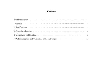
1. Contents
Brief Introduction・・・・・・・・・・・・・・・・・・・・・・・・・・・・・・・・・・・・・・・・・・・・・・・・・・・・・・・・ 1
1. General・・・・・・・・・・・・・・・・・・・・・・・・・・・・・・・・・・・・・・・・・・・・・・・・・・・・・・・・・・・・・・ 2
2. Specifications・・・・・・・・・・・・・・・・・・・・・・・・・・・・・・・・・・・・・・・・・・・・・・・・・・・・・・・・・ 3
3. Controllers Function・・・・・・・・・・・・・・・・・・・・・・・・・・・・・・・・・・・・・・・・・・・・・・・・・・・・ 10
4. Instructions for Operation・・・・・・・・・・・・・・・・・・・・・・・・・・・・・・・・・・・・・・・・・・・・・・・ 20
5. Performance Test and Calibration of the Instrument・・・・・・・・・・・・・・・・・・・・・・・・・・ 35
2. 1
Brief Introduction
Thank you for purchasing the 20MHz/15MHz oscilloscope.
Please read the manual carefully prior to use and keep it well then.
The instrument is produced strictly according to the standards for quality and all the elements are
selected carefully.
After-sales Service: If there is anything wrong with the instrument, please contact our sales center
as soon as possible.
Caution: Only the oscilloscope is in the specified condition, can it be in good working state.
During carriage, the trace of the instrument might slant slightly. If so, please adjust the trace knob
on the front panel to make the trace parallel with the horizontal scale.
3. 2
1. General
20MHz/15MHz series oscilloscope is a portable kind of oscilloscope for two traces. The
bandwidth of 20MHz is 0~20MHz. And 15MHz is of long persistence and slow sweeping with its
bandwidth of 0~15MHz, its vertical deflection factor is 5mV/div and to 1mV/div by Magnification.
Full bandwidth sweeping circuit is used in the sweeping system. The flexible and convenient
triggering mode has the functions for selecting signals from one channel or triggered by Ext signals.
And there is another function of ALT trigger to observe signals from two irrelative channels.
The instrument has the functions of TV-V synchronization and trigger-lock to observe all
kinds of signals stably. And from the terminal for trigger input, CH1 and CH2 signals can be output
along with the triggering channel to connect the Ext frequency counter. 15MHz has the lowest rate
of 10s/div and the longest time is 250s every time.
The instrument is of easy operation with comfortable controllers. Its reasonable structure and
technology makes it conveniently to repair and calibrate.
4. 3
2. Specifications
Item Specification
2.1 Y Deflection Factor
20MHz 15MHz
Operating mode Y1、Y2、ALT、CHOP、ADD、X-Y
Deflection Factor
(Y1 or Y2)
5mV/div~10V/div in 1-2-5 sequence, altogether 11 steps. Error ±5%
MAG Rate ×5 Error ±5%
Frequency Bandwidth
AC: 10Hz~20MHz -3dB
DC: 0~20MHz -3dB
AC: 10Hz~15MHz -3dB
DC: 0~15MHz -3dB
Frequency Bandwidth
by MAG
AC: 10Hz~5MHz -3dB
DC: 0~5MHz -3dB
Rising time ≤18ns, ≤70ns by MAG ≤24ns, ≤70ns by MAG
Overshot ≤5%
5. 4
Item Specification
20MHz 15MHz
Damp ≤5%
Coupling Mode AC、⊥、DC
Input Implement 1±5%MΩ∥≤30pF (direct) 10±5%MΩ∥≤23pF (by probe)
Max Safe Voltage 400V(DC+ACp-p)
Slope Inverting Y2 only
2.2 Triggering System
20MHz 15MHz
Triggering Source Y1、Y2、ALT、POWER、EXT
Coupling AC/DC(EXT)、NORM/TV
Polarity +、-
Synchronized Frequency
Range
Auto: 50Hz~20MHz Auto: 50Hz~15MHz
7. 6
Item Specification
2.3 Horizontal System
20MHz 15MHz
Sweep mode AUTO、TRIG、LOCK、SINGLE
Sweep time Factor
0.1μs/div~0.2s/div
in 1-2-5 sequence
altogether 20 steps
Error ±5%
0.1μs/div~10s/div
in 1-2 (2.5) -5 sequence
altogether 29 steps
Error ±5% in slow sweep
MAG ×5 Error ±10%
2.4 X-Y Mode
20MHz 15MHz
Signal Input X-Axis: Y1 Y-Axis: Y2
Deflection Factor Same as Y1
Frequency Response AC: 10Hz~1MHz -3dB DC: 0~1MHz –3dB
Input Implement Same as Y1
8. 7
Item Specification
20MHz 15MHz
Max Safe Voltage Same as Y1
X-Y Phase Difference ≤3°(DC~50kHz)
2.5 Z-Axis System
20MHz 15MHz
Min Input Level TTL Level
Max Input Voltage 50V(DC+ACp-p)
Input Resistance 10kΩ
Input Polarity Low level to brighten
Frequency Range DC ~5MHz
9. 8
Item Specification
2.6 Signals for Probe Calibration
20MHz 15MHz
Waveform Square wave
Amplitude 0.5±2% Vp-p
Frequency 1±2%kHz
2.7 CRT
20MHz 15MHz
Persistence Middle persistence Long persistence
Working Area 8cm×10cm (1cm=1div)
10. 9
Item Specification
2.8 Power Supply
20MHz 15MHz
Power 220±10%V
Frequency 50±5%Hz
Power Consumption About 35VA
2.9 Physical Characteristics
20MHz 15MHz
Weight 7.2kg
Dimension 320mm×130mm×400mm
11. 10
3. Description of operating controls
3.1 Position Figure of Controllers
Diagram 3-1 Front Panel of 20MHz Oscilloscope
13. 12
Diagram 3-3 Rear Panel
Z AXIS
INPUT
35 33
TRIGGER SIGNAL
OUTPUT
34
WARNING
TO AVOID ELECTRIC SHOCK PROTECTIVE GROUNDING CONNECTOR
IN THE POWER CORD MUST BE CONNECTED TO GROUND
THIS INSTRUMENT CONTAINS NO OPERATOR SERVICEABLE PARTS
INSIDE;REFER SERVICING TO SERVICE TRAINED PERSONNEL ONLY.
DISCONNECT INPUT POWER BEFORE REPLACING FUSE
FOR CONTINUED FIRE PROTECTION USE MANUAL
SPECIFIED TYPE /RATING FUSE ONLY
CONFORMS TO EN61010-1 CAT Ⅱ 600V
!
INPUT:
230V±10%
50Hz±2Hz,
FUSE:
250V F0.5A
35W
LVD
&
EMG
PLEASE READ MANUAL FOR SAFETY
14. 13
3.2 Controllers Function
No. Name Function
(1) POWER Push it down to connect the power and the indicator is on.
(2) INTENSITY Adjust the intensity and turn it clockwise, the trace is brightened.
(3) FOCUS Adjust the focus of CRT and make it be a small and clear dot.
(4) TRACE
ROTATION
Adjust the trace to be parallel with the horizontal scale.
(5) PROBE
ADJUST
One square wave signal with the amplitude of 0.5V and the frequency of
1Hz is output from the terminal and used to adjust the Y-axis deflection
factor and sweep time factor.
(6) AC、⊥、DC Select the inputting coupling mode of Vertical Channel 1. AC: DC part
of the signal is separated then AC part can be observed; DC: The signal
is coupled directly with the channels to observe the DC part of the signal
or when the frequency of the measured signal is very low. And GND is
grounded to determine the trace position when the input terminal is of
zero level.
15. 14
No. Name Function
(7) CH1 (X) Has two functions. It can be used as the input terminal of Vertical
Channel 1 in normal use and it also can be used as the signal input
terminal of Horizontal Channel in X-Y mode.
(8) VOLTS/DIV Select the vertical deflection factor. Altogether 11 steps from 5mV/div.
Select the proper step according to the voltage amplitude of the
measured signal.
(9) VARIABLE Adjust the vertical deflection factor continuously. And the range is no
less than 2.5 times. Turn it to the end clockwise to make it be in the
calibrated position. Then the voltage value can be read out by the
position of VOLTS/DIV and the displayed amplitude.
(10) PULL ×5 Push it down and the gain is magnified to 5 times.
(11) POSITION Adjust the trace position vertically.
16. 15
No. Name Function
(12) MODE Select the working mode in the vertical system.
CH1: Signals on CH1 are displayed only.
CH2: Signals on CH2 are displayed only.
ALT: Observe signals from two channels at the same time. The signals
are displayed alternatively. The mode is usually used at high sweep rate.
CHOP: The signals from two channels are displayed in chopping mode.
It is used to observe the signals at the same time at slow sweep rate.
ADD: Display the adding sum of the signals from two channels. When
CH2 polarity is switched on, the two signals are subtracted.
CH2 Phase-inversion: The signal on CH2 is normal when the knob is
switched off and it would be phase inverted when the knob is switched
on.
(13) AC、⊥、DC Used on CH2 and the functions are the same as (6)
(14) CH2 PLUG Input terminal of CH2 and used as Y input when in X-Y mode.
17. 16
No. Name Function
(15) POSITION Adjust the trace position vertically.
(16) CH2 SWITCH Same as (8)
(17) VARIABLE Same as (9)
(18) CH2 MAG Same as (10)
(19) POSITION Adjust the trace position horizontally.
(20) SLOPE Select the measured signal to be triggered in rising slope or in dropping
slope.
(21) LEVEL Adjust the measured signal to be triggered in one level.
(22) SWEEP
MODE
Select the sweeping mode.
AUTO: Sweeping trace would display when there is no triggering signal;
and there is one, it automatically changes to Trigger Sweep Mode, then
adjust LEVEL to make the waveform display on the screen stably. The
mode is properly used to observe the signals with the frequency over
50Hz.
18. 17
No. Name Function
NORM: No trace would display when there is no triggering signals. If
there is one and the LEVEL is in proper position, the circuit is triggered
to sweep. And it is used to observe signals with
the frequency lower than 50Hz.
LOCK: The waveform can stably display on the screen without adjusting
the LEVEL in LOCK mode.
SINGLE: Used to produce the single sweep. Push down the RESET, and
the circuit is in SINGLE mode. When there is a triggering signal, it will
sweep for once. And the RESET should be pushed down for another
sweep.
(23) TRIG’D
READY
The indicator would be on in two cases: In non-single mode, it means
that the sweep circuit is in triggered mode; and in single mode, it means
that the sweep circuit is ready, and then if there is one input signal, it
will sweep for once and the indicator would be off.
19. 18
No. Name Function
(24) SEC/DIV Select the proper step according to the frequency of the measured
signals. When it is in VARIABLE, the time factor can be read out by the
scale position and the distance between the waves in the horizontal axis.
(25) VARIABLE Adjust the sweep rate continuously and the range is no less than 2.5
times. Rotate it to the end clockwise to the calibrated position.
(26) MAG ×5 Push it down, then the horizontal sweep rate is magnified 5 times.
(27) SLOWSWEEP Used to observe signals with low frequency.
(28) TRIGGER
SOURCE
Used to select different trigger sources.
CH1: The trigger signal is from CH1 in DUAL and from the displayed
channel in SINGLE.
CH2: The trigger signal is from CH1 in DUAL and from the displayed
channel in SINGLE.
ALT: The trigger signal is alternatively from two Y channels in ALT to
observe two signals from two irrelative channels.
POWER: The signal is from power.
EXT: The signal is from the input terminal.
20. 19
No. Name Function
(29) ⊥ The grounded end for the instrument.
(30) AC/DC Coupling mode of external trigger signals. The switch should be in DC
position when the EXT trigger source is selected and the frequency is
very low.
(31) NORM/TV Generally the switch is in NORM position and if TV signals are
measured it should be in TV position.
(32) EXT INPUT The trigger signal is input from the terminal.
(33) Z INPUT For the signal for INTE modulating.
(34) TRIGGER
SIGNAL
OUTPUT
Output CH1 or CH2 signal of 100mV/div with the trigger signal and be
convenient for external frequency counter.
(35) POWER PLUG
WITHFUSE
For the power line of the instrument.
21. 20
4. Operating Methods
4.1 Safety Check
4.1.1The working condition and the power voltage should meet the requirements of the technical
specifications.
4.1.2It is suggested that the instrument should be put in a ventilate place for several hours and
connected with power for one or two hours when it is first used or after storage for a long time.
4.1.3Don’t plug off the cooling hole. Note if the cooling hole is in normal state in continuous usage.
Otherwise, the too high temperature would damage the instrument and shorten the usage life.
4.2 Check for Instrument’s working state
Check if the instrument is in normal working state according to the following steps.
4.2.1Check for the body
Set the relative controllers to the positions as the following table:
22. 21
Table 4-1
Name Position Name Position
INTENSITY In the middle INPUT COUPLING DC
FOCUS In the middle SWEEP MODE Auto
POSITION In the middle SLOPE
MODE CH1 SEC/DIV 0.5ms
VOLTS/DIV 0.1V TRIGGER SOURCE CH1
VARIBALE To the end clockwise COUPLING AC norm
Turn on the power and the indicator is on. After a short time for pre-warming, there is a trace
appeared on the screen. Adjust INTE and FOCUS to make it clear.
Connect the signal of the instrument to Y1 by cable and adjust LEVEL to make the waveform
stable. Set X-POSITION and Y-POSITION to make the displayed waveform be the same as the
following Figure 4-1. Check CH2 using the same method.
23. 22
4.2.2Check for the probe
Connect the probe to two Y input terminals separately. Set VOLTS/DIV to 10mV and attenuate
the probe to ×10, then the waveform shown as Figure 4-1 should appear in the middle of the
screen. If there is any overshot or dropping down, adjust the trimmer on the probe to get the best
waveform shown as Figure 4-4.
Proper Compensation Overshot Waveform Dropping
Figure 4-1 Figure 4-2 Figure 4-3
0
10
100
90
0
10
100
90
0
10
100
90
24. 23
After these jobs are all finished, it is to say that the instrument is in normal working state and
can be used for measurement.
Figure 4-4
4.3 Measuring
4.3.1Voltage Measuring
Generally, rotate VOLTS/DIV to the calibrated position clockwise, then work out the
voltage value of the measured signals directly by the indicated value on VOLTS/DIV.
Since there are DC and AC parts in the measured signal, test should be done according to the
following steps.
a.AC Voltage Measuring:
调整元件TRIMMER
25. 24
If AC part of the signal is measured only, set Y Coupling mode to AC. Adjust VOLTS/DIV to
make the displayed waveform in the middle of the screen. Then rotate LEVEL to make the
waveform stable. Separately adjust Y Position and X Position to read out the waveform displayed
easily, shown as Figure 4-5. With the value indicated by VOLTS/DIV and the distance shown
vertically on the axis, calculate the voltage value by the following formula:
Vp-p=V/DIV×H(DIV)
Veffect=Vp-p/2√2
26. 25
VOLTS/DIV: 2V Vp-p=4.6×2-9.2V
Figure 4-5 AC Voltage Measuring
If the probe used is magnified 10, then the value calculated should time 10.
b. DC Voltage Measuring
If the DC part of a signal is measured, first set Y Coupling mode to GND and adjust Y Position
to make the sweep baseline to be a proper position, then set Y Coupling mode to DC to adjust
LEVEL to synchronize the waveforms. With the vertical distance from the waveform to the basic
0
10
100
90
A
B
Vp-p
27. 26
sweep baseline, read out each voltage value of the signal shown as Figure 4-6.
VOLTS/DIV: 0.5V Vp-p=3.7×0.5=1.85V
Figure 4-6 DC Voltage Measuring
4.3.2 Time Measuring
When the signal cycle or the time factor between two points is measured, operate as said above.
After the waveform is synchronized, time the value indicated by SEC/DIV using the horizontal
0
10
100
90 测量后
测量前
DC Voltage
(After Deflection)
Zero Level
28. 27
distance between two points or the signal cycle. If one part of the signal is measured, pull out MAG
knob to magnify 5. Adjust X Position to move the waveform to the proper position for observation.
Then the value measured should be divided 5.
Calculate the time intervals by the following formula:
Time interval (S)=[Distance between two points (DIV)×Sweep Time Factor (TIME/DIV)]/
Magnification Factor horizontally
Example 1: In Figure 4-7, the horizontal distance between Point A and B is 8 DIV, the sweep
time factor is set to 2ms/div, Horizontal magnification is ×1, then:
Time Interval=8DIV×2ms/DIV/1-16ms
29. 28
Figure 4-7 Measurement of Time Interval
Example 2: In Figure 4-8, the horizontal distance from 10% of the rising slope (Point A) to
90% (Point B) is 1.8DIV, set the sweep rate to 1μs/DIV, the magnification factor is ×5, then:
Rising Time=1.8DIV×1μs/5=0.36μs
0
10
100
90 A B
水平距离
Horizontal
Distance
30. 29
Figure 4-8 Measurement of Rising Time
4.3.3 Frequency Measurement
As to the frequency measurement of the repeated signals, first measure out the signal cycle,
then work it out as following:
f(Hz)=1/T(S)
If the frequency of the measured signal is very high, even if SEC/DIV is set to the fastest step,
0
10
100
90
水平 距 离
B
A
Horizontal
Distance
31. 30
the displayed waveform is still very close. Calculate the value with the cycles displayed in 10DIV
on X-axis for higher accuracy:
f(Hz)=N(cycles)/Values on SEC/DIV×10
4.3.4 Phase or time difference of two relative signals
According to the frequency of the two relative signals, select the proper sweep rate and set
Vertical Mode to ALT or CHOP、Trigger Source as the basic channel. Adjust LEVEL to get stable
waveform. Calculate the time difference with the horizontal difference between the two points on
the two waveforms:
Time Difference=Horizontal Distance(DIV)×Sweep Time Factor(TIME/DIV) /Horizontal
Magnification Factor
In Figure 4-9, the sweep time factor is set to 50μs/DIV, the horizontal magnification factor is
set to ×1, the horizontal distance between the two measured signals is 1.5 DIV, then:
Time Difference=1.5DIV×50μs/DIV/1=75μs
32. 31
Figure 4-9 Time Measurement of Two Relative Signals
If the phase difference between two signals is measured, first get stable waveforms using the
above method, then adjust VOLTS/DIV and VARIABLE of two channels to make the displayed
amplitude be equal. Adjust SEC/DIV in order that the horizontal distance of the measured cycle
displayed on the screen is some integer, then the phase angle is 360°/Horizontal distance of one
cycle(DIV). The horizontal distance of another channel times the phase angle of every division, the
0
10
100
90
A B
参考波形 延迟波形
水平差距Horizontal
Distance
Reference Waveform Delay Waveform
33. 32
result is the phase difference of two relative signals.
Example: In Figure 4-10, the horizontal distance between two measured points on the
waveform is 1 DIV, work out the phase difference using the following formula:
Phase Difference=1DIV×40°/DIV=40°
Figure 4-10 Phase Difference Measurement of two relative Signals
4.3.5 Measurement of Two Irrelative Signals
If two irrelative signals should be measured, set Vertical Mode to ALT and push down CH1 and
0
10
100
90
A
B
参考波形 延迟波形
水平差距Horizontal
Distance
Reference Waveform Delay Waveform
34. 33
CH2, then adjust LEVEL to get synchronized waveforms.
Points for attention:
a.The frequency of the measured signal should not be too low for the mode can be only used
when Vertical Mode is set to ALT. Or the alternative shooting would appear on the two channels.
b. If there is no signal input from one channel, synchronization cannot be got.
4.3.6 TV Signal Measurement
There is a circuit for separating TV-V synchronized signals inside 20MHz oscilloscope. If
TV-V signal is observed, push down the trigger-coupling switch TV. Select the proper triggering
slope according to the slope of the measured TV signal. Adjust LEVEL to get stable
synchronization of TV-V signal.
If TV-H signal is measured, get their synchronization in NORM mode.
4.3.7 X-Y Mode
In some special cases, the trace rotation should be controlled by external signals or X-axis
should be taken as the input terminal for the measured signal, such as: EXT sweep signal、
observation of Lishayu Diagram or used as displaying device for other equipments.
X-Y Mode Operation: Rotate SEC/DIV counterclockwise to the end to X-Y position. Input
X-axis signal from CH1 OR X terminal and read out the deflection factor indicated value by
35. 34
VOLTS/DIV of the channel. But X-axis sensitivity magnification is controlled by Horizontal
Magnification ×5.
4.3.8 External Intensity Control
The modulating signal for adjust INTE can be input from Z-axis Plug on the rear panel. The
slope is that the negative level brightens and positive level disappears. It is often used when one part
of the measured waveform should be marked with INTE.
36. 35
5. Performance Test and Calibration of the Instrument
In order to keep the instrument to be in the best working state after repair or used for a long
time, it should be thoroughly checked and calibrated. And the positions of the elements needing
calibration are as Figure 5-1 shown.
5.1 Calibration of DC Power
Standard Voltage Permitted Range Calibrating Element
+5V ±0.2V 5N3
+9V ±0.2V 5N1
-9V ±0.2V 5N2
+150V ±5V 5R5
+230V ±10V
-1500V ±50V 5R9
37. 36
Figure 5-1 Position Diagram of Elements needing Calibration
5.2 Calibration of CRT Display System
5.2.1 Adjust the controllers on the operating panel to get sweep baseline on the screen at
``
`
7R9 7R7 7R13 2C2 1R29 2C7
5R27
5R29
5R43
3R54R54
4R53
4C29
1C17
4C204R13
1C18
1R84
1R83
1R57
4R9
4R2
1R77
1C8
1R79
1R80
1R81
38. 37
moderate sweep speed. Rotate INTE potential to the point on one third of the full, adjust 5R27 to
get the persistence. Then move the sweep baseline to the up and bottom line, adjust 5R29 in order
that there is no clear distortion of the waveform.
5.2.2 Rotate SEC/DIV counterclockwise to X-Y mode, adjust POSITION to get one bright dot
displayed on the screen with adjusting FOCUS and 5R43 at the same time, then the trace would be
fine and round.
5.3 Adjustment of Probe Calibrating System Signals
Input the signal of standard amplitude and the signal for probe calibration to the same channel
separately. Measure out their difference by comparison. Adjust 7R13 to make the difference the
smallest. Then adjust 7R9 to get the symmetrical waveform. Test its frequency by a frequency
counter. Adjust 7R7 to get the smallest difference.
5.4 Adjustment of Vertical System
5.4.1 Calibration of DC Symmetry
One controller knob on the operating panel. The sweep baseline of Y1 channel is displayed on
the screen. Adjust 1R77 to get the smallest position in vertical axis when VARIABLE is rotated.
Calibrate DC symmetry of Y2 channel by the same method. 1R81 should be adjusted.
5.4.2 Calibrate Y Gain
39. 38
Vertical Mode is set to Y1, and VOLTS/DIV is set to 0.1V. Rotate VARIABLE clockwise to
the end. Input the signal for probe calibration. Adjust 1R79 to get the displayed amplitude be 5DIV.
Switch VOLTS/DIV to 0.5V, push down Y1×. Then adjust 1R80 to get the displayed amplitude be
5DIV. Calibrate Y2 Gain using the same method by adjusting 1R83 and 1R84.
5.4.3 Calibration for Y-Axis Attenuate Frequency Compensation
Input standard square wave of 1kHz to two vertical channels. According to the attenuated waveform
shown on Figure 5-2, adjust the relative elements from small to big to get correct compensation.
41. 40
5.4.4 Calibration of Vertical Instantaneity
Set VOLTS/DIV of two vertical channels to 5mV, rotate VARIABLE clockwise to the end.
Input a square waveform with its rising time ≤1ns to the vertical channels, connect a terminal
resistance of 50Ω to the input terminal of the channel. Adjust the signal amplitude to get the
displayed amplitude be 5DIV. Repeat adjusting 1C8 (CH1)、1C17、1C18 (CH2)、2C2、2C7 to get
the best compensation shown as Figure 5-3, the rising time is ≤18ns.
Figure 5-3 Check for Vertical Instantaneity
0
10
100
90
B
A
≤5%
≤5%
≤18ns
42. 41
5.5 Calibration of Horizontal System
5.5.1 Calibration of Sweep Rate
Set SEC/DIV to 0.5ms, rotate VARIABLE clockwise to the end. Input a standard timebase
signal of 0.5ms, adjust 4R53 to get one cycle per DIV on the screen. Push down MAG ×5 and
adjust 4R54 to get one cycle per 5DIV on the screen.
Spring out MAG ×5, switch SEC/DIV to 0.2ms. the signal would change with it. Adjust 4C20
to get one cycle per DIV displayed on the screen. Check every sweep sequence to make the
accuracy of each sequence more than ±5%.
When the sweep rate is set as very fast, adjust 4C29 to get compensation at the beginning.
Please be careful for all these adjustments interact with each other.
5.6 Adjustment of X-Y Mode
5.6.1 Calibration of X-Axis Symmetry
Set SEC/DIV to X-Y mode. Adjust X POSITION. The cursor would move out of the screen
from left or right, or adjust 4R2.
5.6.2 X Gain Calibration
Set CH1 (X) VOLTS/DIV to 0.1V and input the standard calibrating signal. Adjust 4R9 to get
two cursors with its distance 5DIV horizontally displayed on the screen.
43. 42
The standard used in the instrument:
EN61010-1(1993) Safety requirements for electrical equipment for measurement, control,
and laboratory use
EN-IEC61326-1(1997) EMC requirements for electrical equipment for measurement and
laboratory
The enterprise has passed ISO9001 International Quality System Attestation, the products has been
designed and manufactured according to ISO9001.
Ⅰ
44. 43
Matters needing attention
Please read the following matters needing attention to avoid body damage and prolong the usage
life. The instrument can only be used in specified conditions and only qualified technicians can
repair the machine.
Fire and body damage protection
・Use proper power lines. Only power lines those are specified for the instrument and in the
specified country can be used.
・The instrument should be grounded. The instrument is grounded through the grounding lead of
power lines. The grounding conductor should be grounded to the earth. The grounding terminal on
front panel is connected to the instrument to avoid electric shock and body damage. Be sure that the
instrument is safely grounded before it is connected with any plugs.
・Don’t operate the instrument without covers. Please don’t operate the instrument if its covers
are moved away.
・Use proper fuses. Only the fuses those are specified for the instrument can be used.
・Don’t use the instrument if it is doubt that something is wrong with it. If it is doubt that there
is anything wrong with the instrument, let those specified technicians check the instrument.
・If the oscilloscope is used to measure the voltage in the electric net, some additional measures
should be adapted beforehand. If the probe were connected to the electric net directly, the probe or
Ⅱ
45. 44
the inner circuit of the oscilloscope would be damaged.
Prolong the working life
Storage & usage
・Don’t use the instrument in very cold or hot condition. The working temperature is 0℃~40℃.
Don’t move the instrument from very cold places to very hot places. Or the hydrosphere would
condense inside the instrument and on the screen.
・Don’t put the instrument in very wet places or the places of much dust. The best relative humidity
for usage is 35%—90%.
・Don’t put the instrument in vibrating places or the places of strong magnetic field.
Operation
・The ventilating holes on the instrument cannot be plugged or inserted with metal or leads.
・Don’t put the instrument upside down or pull the instrument with the probes or connecting lines.
・Don’t put electric irons on the surface or frame of the instrument.
Clearing Use soft cloths with neutro-detergent to clean the rust or dust. And the detergent of high
volatility such as benzene cannot be used.
Calibration Period In order to maintain this equipment in stable and efficient operating condition,
calibrate the equipment after every 1,000 hours operating time, or every 1 year, whichever is
shorter.
Ⅲ
Ⅲ
46. 45
The following symbols maybe appear in this manual or the product:
No. Symbol Explanation No. Symbol Explanation
1 AC 7 OFF (power)
2 ~ DC 8 +、- Positive、Negative
3 GND 9 Electric shock warning
4 Protective grounding 10 ! Warning
5 Connected to Frame 11 Push switch controlling in
6 ON (power) 12 Push switch controlling out
Ⅳ