
Recommended
Recommended
More Related Content
What's hot
What's hot (20)
Similar to Eaton Vickers V10 and V20 Hydraulic Vane Pumps
Similar to Eaton Vickers V10 and V20 Hydraulic Vane Pumps (20)
Recently uploaded
Recently uploaded (20)
Eaton Vickers V10 and V20 Hydraulic Vane Pumps
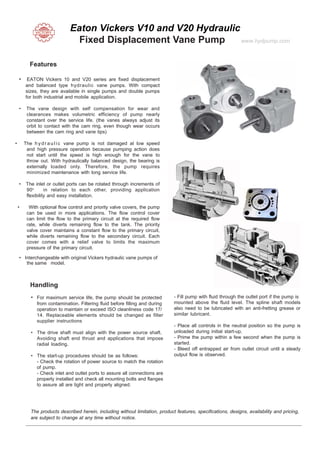
- 1. Eaton Vickers V10 and V20 Hydraulic Fixed Displacement Vane Pump www.hydpump.com Features • EATON Vickers 10 and V20 series are fixed displacement and balanced type hydraulic vane pumps. With compact sizes, they are available in single pumps and double pumps for both industrial and mobile application. • The vane design with self compensation for wear and clearances makes volumetric efficiency of pump nearly constant over the service life. (the vanes always adjust its orbit to contact with the cam ring, even though wear occurs between the cam ring and vane tips) • The h yd r a u l i c vane pump is not damaged at low speed and high pressure operation because pumping action does not start until the speed is high enough for the vane to throw out. With hydraulically balanced design, the bearing is externally loaded only. Therefore, the pump requires minimized maintenance with long service life. • The inlet or outlet ports can be rotated through increments of 90o in relation to each other, providing application flexibility and easy installation. • With optional flow control and priority valve covers, the pump can be used in more applications. The flow control cover can limit the flow to the primary circuit at the required flow rate, while diverts remaining flow to the tank. The priority valve cover maintains a constant flow to the primary circuit, while diverts remaining flow to the secondary circuit. Each cover comes with a relief valve to limits the maximum pressure of the primary circuit. • Interchangeable with original Vickers hydraulic vane pumps of the same model. Handling • For maximum service life, the pump should be protected from contamination. Filtering fluid before filling and during operation to maintain or exceed ISO cleanliness code 17/ 14. Replaceable elements should be changed as filter supplier instructions • The drive shaft must align with the power source shaft. Avoiding shaft end thrust and applications that impose radial loading. • The start-up procedures should be as follows: - Check the rotation of power source to match the rotation of pump. - Check inlet and outlet ports to assure all connections are properly installed and check all mounting bolts and flanges to assure all are tight and properly aligned. - Fill pump with fluid through the outlet port if the pump is mounted above the fluid level. The spline shaft models also need to be lubricated with an anti-fretting grease or similar lubricant. - Place all controls in the neutral position so the pump is unloaded during initial start-up. - Prime the pump within a few second when the pump is started. - Bleed off entrapped air from outlet circuit until a steady output flow is observed. The products described herein, including without limitation, product features, specifications, designs, availability and pricing, are subject to change at any time without notice.
- 2. For more technical information, please contact us. Ordering Code and Specifications Single Pump V20(F) - 1P11S - 1C(8)-(H)-(L) Model V10, V20 Cover Omit - Standard Cover F - Flow Control Cover P - Priority Valve Cover Mounting 1 - 2-Bolt Flange Inlet Port Connection S - 1.3125”-12 Str. thd. (V10) - 1.625”-12 Str. thd. (V20) P - 1.00” NPT (V10) - 1.25” NPT (V20) B - 1.00” BSP (V10) - 1.25” BSP (V20) T - 1.1875”-12 Str. thd. (V10) Shaft Rotation (Viewed from shaft end) Omit - Turn right L - Turn left Pressurer Setting for Flow control and Priority Valve Cover bar (psi) A - 17 (250) F - 103 (1500) B - 34 (500) G - 121 (1750) C - 52 (750) H - 138 (2000) D - 69 (1000) J - 155 (2250) E - 86 (1250) K - 172 (2500) Flow rate Setting for Flow control and Priority Valve Cover L/min (USgpm) 2 - 7.6 (2) 6 - 22.7 (6) 3 - 11.4 (3) 7 - 26.5 (7) 4 - 15.2 (4) 8 - 30.3 (8) 5 - 19.0 (5) Delivery (USgpm at 1200 rpm) V10 - 1, 2, 3, 4, 5, 6, 7 V20 - 6, 7, 8, 9, 11, 12, 13 Outlet Port Connection V10 and V20 S - .750”-16 Str. thd. (V10) - 1.0625”-12 Str. thd. (V20) P - .500” NPT (V10) - .750” NPT (V20) B - .500” BSP (V10) - .750” BSP (V20) V10F, V10P, V20F, and V20P S - .750”-16 Str. thd. for outlet and 1.0625”-12 Str. thd. for tank port (V20F) Outlet Port Position (Viewed from cover end) A - Opposite inlet B - 90o CCW from inlet C - Inline with inlet D - 90o CW from inlet Shaft 1 - Straight keyed 3 - Threaded with woodruff key 6 - Woodruff key stub (V20 only) 11 - Splined 12 - Splined (V10 only) 15 - Splined (V20 only) 38 - Splined P - .750”-16 Str. thd. for outlet and .500” NPT for tank port (V10F and V20F) T - .750”-16 Str. thd. for outlet and tank port (V10F) - .750”-16 Str. thd. for primary outlet and tank port and .875”-14 Str. thd. for secondary outlet (V20P) K - .5625”-18 Str. thd. for primary outlet and tank port and .750”-16 Str. thd. for secondary outlet (V10P) Model Series Ring Size Delivery at 1200 r/min & 7 bar (100 psi) USgpm Geometric Displacement cm 3 /r (in 3 /r) Delivery at 1500 r/min & 7 bar (100 psi) L/min (USgpm) Maximum Pressure bar (psi) Maximum Speed rpm Minimum Speed rpm Weight kg (lb) V10 V10F V10P 1 2 3 4 5 6 7 3.3 (0.20) 6.6 (0.40) 9.8 (0.60) 13.1 (0.80) 16.4 (1.00) 19.5 (1.19) 22.8 (1.39) 4.70 (1.25) 9.40 (2.50) 14.20 (3.75) 18.90 (5.00) 23.60 (6.25) 28.40 (7.50) 33.10 (8.75) 172 (2500) 172 (2500) 172 (2500) 172 (2500) 172 (2500) 152 (2200) 138 (2000) 4800 4500 4000 3400 3200 3000 2800 650 650 650 650 650 650 650 4.5 - 6.8 (10 - 15) V20 V20F V20P 6 7 8 9 11 12 13 19.5 (1.19) 22.8 (1.39) 26.5 (1.62) 29.7 (1.81) 36.4 (2.22) 39.0 (2.38) 42.4 (2.59) 28.39 (7.50) 33.11 (8.75) 37.85 (10.00) 42.57 (11.25) 52.04 (13.75) 56.77 (15.00) 61.50 (16.25) 172 (2500) 172 (2500) 172 (2500) 172 (2500) 172 (2500) 152 (2200) 152 (2200) 3400 3000 2800 2800 2500 2400 2400 650 650 650 650 650 650 650 7.3 - 8.2 (16 - 18)
- 3. V2010 douoble vane pump V10 vane pump V20 vane pump V2010 1F 11B 2B 11CC 12 R V10 1B 3B 1D 20 V20 1E11S 23B 11 V2010 1F 11B 2B 1AA 12 R V10 1B 4B 11A 20L V20 1P13S 1C 11 V2010 1F 11B 2B 1CC 12 R V10 1P1P 1C20 V20 1B 11B 11C 11 V2010 1F 11B 3B 1AA 12 R V10 1B 1B 11A 20 V201B 11B 15A11 V2010 1F 11B 3B 1B A 12 R V10 1B 1B 1A 20 V20 1B 11B 1A 11 V2010 1F 11B 3B 1CC 12 R V10 1B 2B 11A 20 V20 1B 11B 1B 11 V2010 1F 11B 3B 1DD 12 R V10 1B 2B 11C 20 V20 1B 11B 1B 11 V2010 1F 11B 4B 1AA 12 R V10 1B 2B 11C 20L V20 1B 11B 1C 11 V2010 1F 11B 4B 1AC 12 R V10 1B 2B 1A 20 V20 1B 11B 38C 11 V2010 1F 11B 5B 1AA 12 R V10 1B 2B 1A 20L V20 1B 11B 62C 11 V2010 1F 11B 5B 1B B 12 R V10 1B 2B 1C 20 V20 1B 11B 62C11 V2010 1F 11B 5B 1CC 12 R V10 1B 2B 1D 20 V20 1B 11B 6C11 V2010 1F 11B 7 1AA 12 R V10 1B 2B 38C 20 V20 1B 12B 1A 11 V2010 1F 11S3S 11AA 12 R V10 1B 3B11A20 V20 1B 12B 1C 11 V2010 1F 12B 2B 1AA 12 R V10 1B 3B11B 20 V201B 13B 11C11 V2010 1F 12B 2B 1CC 12 R V10 1B 3B 11C 20 V201B 13B 15A11 V2010 1F 12B 3B 1AA 12 R V101B 3B11C20L V20 1B 13B 15C 11 V2010 1F 12B 4B 1AA 12 R V10 1B 3B 1A 20 V20 1B 13B 1A 11 V2010 1F 13B 2B 1AA 12 R V10 1B 3B 1A 20L V20 1B 13B 1A 11L V2010 1F 13B 2B 1AD 12 R V10 1B 3B 1C 20 V20 1B 13B 1C 11 V2010 1F 13B 2B 1CC 12 R V101B 3B 38C20 V20 1B 13B 1D 11 V2010 1F 13B 2B 1DA 12L V101B 3B38C20L V201B 13B 3C11 L V2010 1F 13B 3B 1AA 12 R V10 1B 4B 11A 20 V20 1B 13B 62A 11 V2010 1F 13B 3B 1CC 12 R V10 1B 4B 11C 20 V20 1B 13B 62C 11 V2010 1F 13B 4B 1AA 12 R V10 1B 4B 1A 20 V20 1B 5B 1C11 V2010 1F 13B 4B 1B B 12 R V10 1B 4B 1A 20L V201B 6B11C11 V2010 1F 13B 4B 1CC 12 R V10 1B 4B 1B 20 V20 1B 6B 1A 11 V2010 1F 13B 5B 1AA 12 R V10 1B 4B 1C 20 V20 1B 6B1A11 L V2010 1F 13B 5B 1AC 12 V10 1B 4B 38C20 V20 1B 6B1B 11 V2010 1F 13B 5B 1AD 12 R V10 1B 5B 11C 20 V20 1B 6B 1C 11 V2010 1F 13S1S 1B A12 V10 1B 5B 11C 20L V201B 6B 3A 11 V2010 1F 13S6S 1AA 12 R V10 1B 5B 1A 20 V20 1B 6B 3C 11 V2010 1F 5B3B 1CC 12 R V10 1B 5B 1A20L V20 1B 7B 1A 11 V2010 1F 6B2B 1AA 12 R V10 1B 5B 1B 20 V20 1B 7B 1A 11L V2010 1F 6B4B 1CC 12 R V10 1B 5B 1C 20 V20 1B 7B 1B 11 V20101F 6B6B1CC12R V10 1B 5B 1D 20 V20 1B 7B 1C 11 V2010 1F 7B2B 1AA 12 R V10 1B 5B 38C 20 V20 1B 7B 1C 11L V2010 1F 7B2B 1CC 12 R V10 1B 5B 41B 20L V20 1B 7B 3C 11 V2010 1F 7B3B 1AA 12 R V10 1B 5B 41B 20L V20 1B 7B 62A 11 V2010 1F 7B3B 1CC 12 R V10 1B 5B 41B 20R V20 1B 8B 1A 11 V2010 1F 7B4B 1AA 12 R V10 1B 5B 41D 20L V20 1B 8B 1A11L V2010 1F 7B5B 1AA 12 R V10 1B 5B 41D 20R V20 1B 8B 1B 11 V2010 1F 7B5B 1CC 12 R V10 1B 6B 11A 20 V20 1B 8B 1C 11 V2010 1F 7B6B 1AA 12 R V10 1B 6B 11C 20 V20 1B 8B 1D11 V2010 1F 7S3R 11DC12L V10 1B 6B 11C 20L V20 1B 8B 62A 11 V2010 1F 8B2B 1AA 12 R V10 1B 6B 1A 20 V20 1B 9B 1A 11 V2010 1F 8B3B 1AA 12 R V10 1B 6B1A20L V20 1B 9B 1A 11L V2010 1F 8B3B 1CC 12 R V10 1B 6B1B 20 V20 1B 9B 1B 11 V2010 1F 8B4B 1AA 12 R V10 1B 6B1B 20L V20 1B 9B 1C 11 V2010 1F 8B4B 1AB 12 R V10 1B 6B 1C 20 V20 1B 9B 1D 11 V2010 1F 8B4B 1CC 12 R V10 1B 7B 11A 20 V201 B9B62A11 V2010 1F 8B4B 1DD 12L V10 1B 7B 11C 20 V20 1B 9B 62C 11 V2010 1F 8B5B 1AA 12 R V10 1B 7B 1A 20 V20 1B 9B6A11 V2010 1F 8B5B 1CC 12 R V10 1B 7B 1A 20L V20 1P11P 1A 11 V2010 1F 8B6B 1AA 12 R V10 1B 7B 1B 20 V20 1P11P 1C 11 V2010 1F 8S2S 1B B 12 R V10 1B 7B 1C 20 V20 1P11P 3C 11 V20101F 9B2B1AA12L V10 1P1P 11C20 V20 1P11S 1A 11 V2010 1F 9B2B 1AA 12 R V10 1P1P 11C20L V20 1P11S 1C 11 V2010 1F 9B2B 1CC 12 R V10 1P1P 1A20 V20 1P13P 1A11 Vickers V10 V20 Single and doulbe vane pump
- 4. V2010 1F 9B3B 1AA 12 R V10 1P2P 1A 20 V20 1P13P 1A11L V2010 1F 9B3B 1CC 12 R V10 1P2P 1C 20 V20 1P13P 1C 11 V2010 1F 9B4B 1AA 12 R V10 1P 3P 12C 20 V20 1P13P 1C11L V2010 1F 9B5B 1AA 12 R V10 1P3P 1A 20 V20 1P13S 11C11 LH V2010 1F 9B5B 1CC 12 R V10 1P3P 1C 20 V20 1P6P 1A 11 V2010 1F 9B6B 1CC 12 R V10 1P4P 1A 20 V20 1P7P 1C 11 V2020 1F 11B 11B 1AA 30 V10 1P4P 1C 20 V20 1P7S 1A11 V2020 1F 11B 11B 1CC 30 V10 1P5P 1A 20 V20 1P8P 1A 11 V2020 1F 11B 6B1AA30 V10 1P5P 1C 20 V20 1P8P 1C 11 V2020 1F 11B 7B 1AA 30 V10 1P6P 1A 20 V20 1P8S 1C11 V20201F 11B 7B1CC30 V10 1P7P 1C 20 V20 1P9P 1C 11 V2020 1F 11B 8B 1AA 30 V10 1S2S 11A20L V20 1P9S 1A 11 V2020 1F 11B 8B 1CC 30 V10 1S3S 11A 20 V20 1S10S23C 11 V2020 1F 11B 9B 1AA 30 V10 1S3S 1C 20 V20 1S13S 15C 11 V2020 1F 12B 6B 1CC30L V10 1S4S 1C 20 V20 1S13S 1C 11 V20201F 13B 11B 100AA 30L V10 1S5S 11C20 V20 1S13S 1C11L V2020 1F 13B 11B 1AA 30 V10 1S5S 1C 20 V20 1S13S 6D 11L V2020 1F 13B 11B 1AA 30L V10 1S7S 1A20 V20F 1S10S23C 11 V2020 1F 13B 11B 1CC 30 V10F 1P7P 38D5F 20 V20F 1S13S 15C 11 V2020 1F 13B 6B 1AA 30 V10F 1B 6B 11C 20 V20F 1B 8B 1D11 V2020 1F 13B 7B1AA30 V10F 1B 6B 11C 20L V20F 1B 8B 62A 11 V2020 1F 13B 7B 1CC 30 V10F 1B 6B 1A 20 V20F 1B 9B 1A 11 V2020 1F 13B 8B 1AA 30 V10F1B 6B1A20L V20F 1B 9B 1A 11L V2020 1F 13B 9B 1AA30 V10F1B 6B1B 20 V20F 1B 9B 1B 11 V2020 1F 13B 9B 1CC 30 V10F1B 6B1B 20L V20F 1B 9B 1C 11 V2020 1F 13S9S 1CC30 V10F 1B 6B 1C 20 V20F 1B 9B 1D 11 V2020 1F 7B6B 1AA 30 V10F 1B 7B 11A 20 V20F1 B9B62A11 V2020 1F 7B7B 1AA 30 V10F 1B 7B 11C 20 V20F 1B 9B 62C 11 V2020 1F 7B7B 1CC 30 V10F 1B 7B 1A 20 V20F1B 9B6A11 V2020 1F 8B6B 1AA30 V10F 1B 7B 1A 20L V20F 1P11P 1A 11 V2020 1F 8B7B 11CC 30 V10F 1B 7B 1B 20 V20F 1P11P 1C 11 V2020 1F 8B8B 1AA 30 V10F 1B 7B 1C 20 V20F 1P11P 3C 11 V2020 1F 8B8B 1CC 30 V10F 1P1P 11C20 V20F 1P11S 1A 11 V20201F 8B8B1DD30L V10F 1P1P 11C20L V20F 1P11S 1C 11 V2020 1F 8S7S 1AA30 V10F 1P1P 1A20 V20F 1P13P 1A11 V2020 1F 9B7B 1AA 30 V10F 1P2P 1A 20 V20F 1P13P 1A11L V2020 1F 9B7B 1CC 30 V10F 1P2P 1C 20 V20F 1P13P 1C 11 V2020 1F 9B8B 1AA30 V10F 1P 3P 12C 20 V20F 1P13P 1C11L V2020 1F 9B9B 1AA 30 V10F 1P3P 1A 20 V20F 1P13S 11C11 V2020 1F 9S11S 11CC30 V10F 1P3P 1C 20 V20F 1P6P 1A 11 V2020F 1F 11S8T 11AC3H 30 V10F 1P4P 1A 20 V20F 1P7P 1C 11 V2020F 1F 11S8T 11DC4H 30 V10F 1P4P 1C 20 V20F 1P7S 1A11 V2020F 1F 11S8T 11DC4H 30 V10F 1P5P 1A 20 V20F 1P8P 1A 11 V2020F 1F 7S6T 11DC3H 30R V10F 1P5P 1C 20 V20F 1P8P 1C 11 V2020F 1F 9S7T 11DC4H 30R V10F 1P6P 1A 20 V20F 1P8S 1C11 V2020F 1F 9S8T 11B C3H 30 R V10F 1P7P 1C 20 V20F 1P9P 1C 11