2. 1
A First for Slider-type ROBO Cylinders!
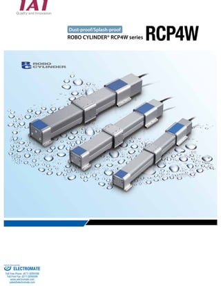
Dust-proof/Splash-proof Performance of IP65,
Plus At-will Installation Configuration Flexibility
1 Dust-proof/Splash-proof Performance of IP65
A special structure where the base is positioned upside down to position the opening at the bottom
which achieves high dust-proof/splash-proof performance of IP65 for the first time with slider-type
ROBO Cylinders.
First digit
Features
IP Marking
IP Classes
Protection against the human body and solid objects
Protection against the intrusion of water
I P
IP class Description Applicable IAI products
IP67
Solid objects Fully protected against the entry of powder dust
into the equipment.
Water Even when the equipment is submerged in water,
water does not enter the equipment.
IP65
Solid objects Fully protected against the entry of powder dust
into the equipment.
Water The equipment receives no harmful effect even
when directly hit by water jets from any direction.
IP54
Solid objects Dust that would affect the operation of the
equipment does not enter the equipment.
Water
The equipment receives no harmful effect even
when contacted by water splashes from any
direction.
IP50
Solid objects Dust that would affect the operation of the
equipment does not enter the equipment.
Water The equipment is not protected against water.
Slider type
RCP2W-SA16C
Slider type
RCP4W
Slider type
ISWA/ISPWA
Pulse motor rod type
RCP2W-RA4C/RA6C
SCARA robot
IX-NNW
High-thrust rod type
RCP2W-RA10C
24-V servo motor rod type
RCAW-RA3/RA4
200-V servo motor rod type
RCS2W-RA4
Small gripper (dust-proof type)
RCP2W-GR
First digit
Second digit
Sold & Serviced By:
ELECTROMATE
Toll Free Phone (877) SERVO98
Toll Free Fax (877) SERV099
www.electromate.com
sales@electromate.com
3. 2
RCP4W
2 Compact
3
4
5
IAI’s splash-proof single-axis robots (ISWA series) have been made smaller to approx. 60% in cross-section
area ratio while keeping the excellent splash-proof performance of ISWA robots. (60% is based on
comparison of ISWA-S and RCP4W-SA5C)
ISWA RCP4W
Type L Type M Type S SA7C SA6C SA5C
(Actuator width) (Actuator width) (Actuator width) (Actuator width) (Actuator width) (Actuator width)
Mount on the Wall or Hang from the Ceiling
Wall-mounting brackets and ceiling-mounting brackets are available as options, which significantly
increase the freedom of installation.
Installable on All Four Sides
of the Top, Bottom, Left and
Right of the Table
The table, positioned in a manner wrapping around
the actuator, has tapped holes on all four sides of the
top, bottom, left and right to increase the freedom of
actuator installation.
Choice of Grease
You can select either industrial grease (Daphne Eponex
No. 2) (standard) or food grade grease (Medallion FM No.
1) for the guides and ball screw in the actuator.
w
Stroke (mm)
100 to 1200
(Available in 50
increments)
100 to 1000
(Available in 50
increments)
100 to 600 (Available
in 50 increments)
100 to 700 (Available
in 50 increments)
100 to 600 (Available
in 50 increments)
100 to 500 (Available
in 50 increments)
Maximum speed
(mm/s)
1000 1000 800 530 400 330
Ceiling mount (bracket on the left)
(Option code: HFL)
Wall mount sideways on the left
(Option code: TFL)
Ceiling mount (bracket on the right)
(Option code: HFR)
Wall mount sideways on the right
(Option code: TFR)
Top side of the table
Right side of the table
Standard grease
Industrial
grease
Daphne Eponex
No. 2
Optional
Food grade
grease
Medallion
FM No. 1
Selectable
Left side of the table
Bottom side of the table
Sold & Serviced By:
ELECTROMATE
Toll Free Phone (877) SERVO98
Toll Free Fax (877) SERV099
www.electromate.com
sales@electromate.com
4. 3
Specification List
Series Type
Actuator
width
(mm)
System Configuration * For details on each device, refer to the RCP4 catalog.
PLC
5m
Take note that, with the RCP4W series, the horizontal payload,
the dynamic allowable moments, the overhang load length
and the maximum stroke vary depending on whether the
actuator is operated with its brackets on both ends fixed
(both ends fixed) or with only the motor-side mounting
bracket fixed in a cantilever configuration (cantilever).
Base Specifications (Both Ends Fixed)
Cantilever
Motor
type
Ball
screw
lead
(mm)
Maxi-mum
speed
(mm/s)
Acceleration
(G)
Horizontal payload (kg) Positioning
repeatability
(mm)
Dynamic allowable
moment (N•m)
Overhang
load
length
(mm)
Stroke (mm) Page
Rated
Maxi-mum
Rated
acceleration
Maximum
acceleration Ma Mb Mc
RCP4W
SA5C 55 35
10 330
0.3 0.6
5 2
±0.02
3.4 4.9 8 125
100 to 500 (Available in
50-mm increments)
P5
5 165 10 4
SA6C 62 42
12 400 7.5 3
4.7 6.7 11 150
100 to 600 (Available in
50-mm increments)
P7
6 200 15 6
SA7C 77 56
16 530 10 4
6.1 8.8 16.8 175
100 to 700 (Available in
50-mm increments)
P9
8 265 20 8
Series Type
Actuator
width
(mm)
Motor
type
Ball
screw
lead
(mm)
Maxi-mum
speed
(mm/s)
Acceleration
(G)
Horizontal payload (kg) Positioning
repeatability
(mm)
Dynamic allowable
moment (N•m)
Overhang
load
length
(mm)
Stroke (mm) Page
Rated
Maxi-mum
Rated
acceleration
Maximum
acceleration Ma Mb Mc
RCP4W
SA5C 55 35
10 330
0.3 0.6
1.5 0.5
±0.02
1.7 2.5 4 75
150 max.
P5
5 165 2 1
SA6C 62 42
12 400 3 1.5
2.4 3.4 5.5 90 P7
6 200 4.5 2.5
SA7C 77 56
16 530 4.5 3
3.1 4.4 8.4 105 P9
8 265 7 4
(Both ends fixed) (Cantilever)
Option
Touch-panel teaching pendant
<Model number: CON-PTA/CON-PDA/
CON-PGA>
Option
Option
Supplied with the actuator
Supplied with the controller
Supplied with the simple
absolute specification
PC software
24-VDC power supply
Integrated motor/encoder cable
PIO cable
Absolute battery unit
Simple absolute battery
RS232 connection type
<Model number: RCM-101-MW>
USB connection type
<Model number: RCM-101-USB>
<Model number: PS-241
(100-V input)>
<Model number: PS-242
(200-V input)>
Standard cable
<Model number: CB-CA-MPA >
Robot cable
<Model number: CB-CA-MPA -RB>
Standard length: 1m / 3m / 5m
<Model number: CB-PAC-PIO020>
Standard length: 2m
<Model number SEP-ABU>
<Model number AB-7>
Actuator RCP4W series
Controller
PCON-CA
Sold & Serviced By:
ELECTROMATE
Toll Free Phone (877) SERVO98
Toll Free Fax (877) SERV099
www.electromate.com
sales@electromate.com
5. 4
RCP4W
Model number
Actuator
RCP4W I P3
Series Type code Ball screw
Applicable
lead
Stroke
(mm)
Motor
type
controller
Cable Options
length
Encoder
type
SA5C Actuator width 55 mm
SA6C Actuator width 62 mm
SA7C Actuator width 77 mm
N No cable
P 1 m
S 3 m
M 5 m
X
Length
designation
R Robot cable
A1 Cable exit from the left
A3 Cable exit from the right
AL Additional alumite coating
GE
Food grade grease (edible
grease)
NM Non-motor side specification
HFL Ceiling mount (left)
HFR Ceiling mount (right)
TFL
Wall mount sideways on
the left
TFR
Wall mount sideways on the
right
35P 35 motor
42P 42 motor
56P 56 motor
5 Lead 5
6 Lead 6
8 Lead 8
10 Lead 10
12 Lead 12
16 Lead 16
I Incremental P3 PCON-CA
Actuator Options
100 100mm
~
~
700 700mm
(Can be set in 50-mm increments.)
Optional Cable Exit Direction
Code: A1, A3
You can select one of the following three cable exit directions.
If no direction is specified, the cable is exited from the rear.
Exit from the right
side face
Option code: A3
Exit from the left
side face
Option code: A1
Exit from the rear
(standard)
Option code: (Blank)
Food Grade Grease (Edible Grease)
Code: GE
Normally industrial grease is applied to the guides and ball screw of the
actuator. You can change this grease to food grade grease (edible grease).
Actuator Mounting Bracket
You can change the bracket for securing the actuator so that
the actuator can be installed directly on the ceiling or wall
surface (left or right).
Code: HFL, HFR, TFL, TFR
Horizontal mount
(standard)
Option code: (Blank)
Ceiling mount
(bracket installed
on the left)
Option code: HFL
Handling Precautions
Additional Alumite Coating
Code: AL
The actuator is coated with alumite, but alumite
has been removed in the machined areas of the
table and front/rear mounting brackets. This option
adds alumite coating to these areas. (This option is
recommended if the actuator will come in contact
with water.)
Non-motor side Specification
You can change the normal slider position of the
actuator (motor side) to the non-motor side.
Code: NM
* Right and left of the wall mount represent the directions as viewed from the motor side.
Refer to P. 11 and 12 for detailed drawings.
Ceiling mount
(bracket installed
on the right)
Option code: HFR
Wall mount sideways
on the left
Option code: TFL
Wall mount sideways
on the right
Option code: TFR
1. This actuator cannot be used in applications where it comes in direct contact with food which will be sold.
2. Keep the acceleration/deceleration at or below the maximum value. If the actuator is operated beyond the maximum acceleration/deceleration
(0.6 G), abnormal noise/vibration, failure or shorter life may result.
3. Keep the allowable load moments and overhang load length within the allowable values. If the actuator is operated beyond the allowable values,
abnormal noise/vibration, failure or shorter life may result.
4. The actuator must be installed horizontally. It can be hung from the ceiling or mounted on the wall only when a dedicated bracket is used.
5. If the actuator is used in an environment subject to powder dust or water splashes, supply air from the air supply port provided on the rear of the
actuator (air purge). For the amount of air to be supplied, etc., refer to the page of the specific model.
6. Consult IAI on a special environment (such as when a chemical coolant other than water is used).
Sold & Serviced By:
ELECTROMATE
Toll Free Phone (877) SERVO98
Toll Free Fax (877) SERV099
www.electromate.com
sales@electromate.com
6. 5
RCP4W-SA5C
ROBO Cylinder Splash-proof slider type Actuator width: 55 mm
Pulse motor Coupling specification
Payload by Acceleration/Deceleration
With the RCP4W series, the payload remains the same
even when the speed is raised.
However, the payload will drop if the acceleration is
raised. Check on the table below.
25
20
15
10
5
4
8
4
6
10
5
3 2
Lead 5
Lead 10
0
0.0 0.1 0.2 0.3 0.4 0.5 0.6
Diagram of Acceleration/Deceleration vs. Payload
1
[Cantilever]
1.5
1
11.2.2
0.7 0.5
2
Lead 5
Lead 10
1.5 1.5
Actuator Specifications
Leads and Payloads Stroke and Maximum Speed
Options Actuator Specifications
(unit: mm/s)
L
Overhang load lengths
L
Allowable load moment directions
~
~
~
~
~
~
~
~
Ma Mb Mc Ma Mc
Model number Lead
(mm)
Maximum horizontal payload (kg) Maximum
push force
(N)
Positioning
repeatability
(mm)
Stroke
Supported on (mm)
both ends Cantilever
RCP4W-SA5C-I-35P-10- 1 -P3- 2 - 3 10 5 1.5 66.9
±0.02
100 to 500
(in 50-mm
RCP4W-SA5C-I-35P-5- 1 -P3- 2 - 3 5 10 2 147.9 increments)
Stroke (mm) Standard price
100 -
150 -
200 -
250 -
300 -
350 -
400 -
450 -
500 -
Item Description
Drive system Ball screw φ8 mm, rolled C10
Positioning repeatability ±0.02mm
Lost motion 0.1 mm or less
Static allowable
moment
Supported on both ends Ma: 5.9 N•m Mb: 8.4 N•m Mc: 13.7 N•m
Cantilever Ma: 2.9 N•m Mb: 4.2 N•m Mc: 6.8 N•m
Dynamic allowable
moment (*)
Supported on both ends Ma: 3.4 N•m Mb: 4.9 N•m Mc: 8.0 N•m
Cantilever Ma: 1.7 N•m Mb: 2.5 N•m Mc: 4.0 N•m
Overhang load
length
Supported on both ends 125mm or less
Cantilever 75 mm or less
Protective structure IP65 (with air purge)
Ambient operating temperature, humidity 0 to 40°C, 85% RH or less (Non-condensing)
Name Option code See page Standard price
Cable exit from the left side face A1 P4
-
Cable exit from the right side face A3 P4
Additional alumite coating AL P4 -
Food grade grease (edible grease) GE P4
-
Non-motor side specification NM P4
Ceiling mount (bracket mounted on the left) HFL P4
Ceiling mount (bracket mounted on the right) - HFR P4
Wall mount sideways on the left TFL P4
Wall mount sideways on the right TFR P4
(*) Based on 5,000 km of traveling life
Notes
on
selection
(1) This actuator is designed exclusively for horizontal installation. It cannot be installed vertically.
When hanging the actuator from the ceiling or mounting it on the wall, be sure to do so using
an optional dedicated bracket.
(2) The payload varies depending on the acceleration/deceleration. The upper limit of
acceleration/deceleration is 0.6 G.
(3) The cable joint connector is not splash-proof, so install the connector in a location where it
will not come in contact with water.
(4) Refer to the page at right for the air tube length and air flow rate when implementing air purge.
100 to 500
(in 50-mm increments)
10 330
5 165
35P: Pulse motor
I: Incremental size 35
specification
P3:PCON-CA Refer to the option
list below.
100 : 100mm
500 : 500mm
(Can be set in
50-mm
increments.)
* Also select code “I”
for the simple absolute
specification.
10 : 10mm
5 : 5mm
SA5C
Type
I
Encoder
type
35P
Motor type
P3
Applicable
Lead Stroke controller Cable length Options
RCP4W
Series
8
6
4
2
0
0.0 0.1 0.2 0.3 0.4 0.5 0.6
* The RCP4W can be
operated only with
the PCON-CA
Model
Specification
Items
~
N: None
P: 1 m
S: 3 m
M: 5 m
X : Length designation
R : Robot cable
Diagram of Acceleration/Deceleration vs. Payload
[Supported at Both Ends]
Payload (kg)
Payload (kg)
Acceleration/deceleration (G)
Acceleration/deceleration (G)
Legend 1 Stroke 2 Cable length 3 Options
Stroke
Lead
Type Cable symbol Standard price
Standard type
P (1m) -
S (3m) -
M (5m) -
Special length
X06 (6m) X10 (10m) -
X11 (11m) X15 (15m) -
X16 (16m) X20 (20m) -
Robot cable
R01 (1m) R03 (3m) -
R04 (4m) R05 (5m) -
R06 (6m) R10 (10m) -
R11 (11m) R15 (15m) -
R16 (16m) R20 (20m) -
1 Stroke
3
2 Cable length
Sold & Serviced By:
ELECTROMATE
Toll Free Phone (877) SERVO98
Toll Free Fax (877) SERV099
www.electromate.com
sales@electromate.com
7. 6
Materials of Main Components
Base Extruded aluminum (A6063) Surface treatment: Alumite coating
Table Extruded aluminum (A6063) Surface treatment: Alumite coating (excluding machined areas)
Mounting bracket (front/rear) Extruded aluminum (A6063) Surface treatment: Alumite coating (excluding machined areas)
Side cover Extruded aluminum (A6063) Surface treatment: Alumite coating
Motor cover Die-cast aluminum (ADC12) Surface treatment: Alumite coating + Paint
Front cover Die-cast aluminum (ADC12) Surface treatment: Alumite coating + Paint
Seal Urethane rubber (U)
Actuator cable Polyvinyl chloride (PVC) * High flex type cable
Air purge joint Polyphenylene sulfide (PPS)
2
3
4
5
* Alumite coating has been removed in the machined areas of the table 2 and mounting bracket 3 . To add alumite coating to
these areas, specify the "Additional alumite coating (code: AL)" option.
22.5 7.5 35 7.5 30 30
L
2-M3, depth 3 2-φ4H7, depth 4
4-M4, depth8
4-M3, depth 7
A 61
45 10 STROKE 50 29 90
5 5
25
7.5 35 7.5
ME SE
5 5
Dimensional Drawings
5 5
5 10 20 10 5
45
10
70
50
B
D
C
5 35
12.5 20
22.5
75
41 22.5
5
85
7.5
25
20
25
(2m)
Cable exit from the left side face
Air supply port φ6
for air purge Motor height:
(17)
(17)
55
70
CAD drawings can be downloaded
from the website.
Applicable Controller
Dimensions and Mass by Stroke
2-φ3H7, depth 5
8-M3, depth 6
RCP4W series actuators can be operated with the controllers indicated below. Select the type
according to your intended application.
Title External view Model number Features Maximum number of
Cable exit from the
right side face
positioning points Input power Power supply capacity Standard
price
56
Reference
page
Positioner type
(NPN specification) PCON-CA-35PI-NP- -0-
Register positions to move the
actuator into the controller
beforehand, and specify the number
corresponding to each desired
position to operate the actuator.
512 points
DC24V
Rated: 3.5 A
Maximum: 4.2 A
-
P13
Positioner type
(PNP specification) PCON-CA-35PI-PN- -0-
Pulse-train type
(NPN specification) PCON-CA-35PI-PLN- -0- The actuator can be operated freely
via pulse-train controller from an
external output device.
— -
Pulse-train type
(PNP specification) PCON-CA-35PI-PLP- -0-
Stroke 100 150 200 250 300 350 400 450 500
L 385 435 485 535 585 635 685 735 785
A 324 374 424 474 524 574 624 674 724
B 256.5 306.5 356.5 406.5 456.5 506.5 556.5 606.5 656.5
C 221.5 271.5 321.5 371.5 421.5 471.5 521.5 571.5 621.5
D 204 254 304 354 404 454 504 554 604
Mass (kg) 2.8 2.9 3.1 3.2 3.4 3.5 3.7 3.8 4.0
* See P11 for the dimensional drawing for
the ceiling mount specification. See P12 for
the dimensional drawing for the wall
mount specification.
*1 Connect the motor and encoder cables.
*2 During home return, be careful to avoid interference from
peripheral objects because the slider travels until the
mechanical end.
*3 Reference position for calculating moments.
• The above correlation diagram assumes an air tube of 6 mm in outer diameter
and 4 mm in inner diameter. (A joint of 6 mm in outer diameter is used on the
actuator side.)
• Use the correlation diagram as a reference to determine an appropriate pressure
and air tube length in such a way that the air flow rate will become 40 NL/min or
more (clean dry air).
Note on Push-motion Operation
When performing push-motion operation, make sure the reactive
moment generated by the push force does not exceed 80% of the
dynamic allowable moment (Ma or Mb) specified in the catalog.
In push-motion operation, the travel speed is fixed at 25 mm/s.
200
180
160
140
120
100
80
60
40
20
0
0 5 10 15 20 25
400
350
300
250
200
150
100
50
0
10 20 30 40 50 60 70 80
(Note) These actuators cannot be operated with controllers
other than the PCON-CA.
1
6
7
8
9
Correlation Diagram of Air Tube
Length vs. Air Flow Rate Push Force of RCP4W-SA5
Air tube length (m) Current-limiting value (%)
Air flow rate (NL/min)
Push force (N)
Pressure: 0.3 MPa
Pressure: 0.2 MPa
Pressure: 0.1 MPa
Lead 5
Lead 10
35 (reamed hole pitch ±0.02)
25 (reamed hole pitch ±0.02)
22.5
(from the actuator mounting surface)
2-φ4H7, depth 4
(same on the opposite side)
4-M4, depth 6
(same on the opposite side)
Cable joint
connector *1
Slider width: 70
Bracket width: 67
Actuator height: 63.5
Slider height: 65
Reference position
for moment offset *3
Home
(100 or more)
Cable exit from the left side face
Cable exit from the right side face
2-φ4.1, depth 4
30 (reamed hole pitch ±0.02)
2-φ4H7, depth 4 8-M4, through
8-φ4.5 hole
75 (reamed hole pitch ±0.02)
Sold & Serviced By:
ELECTROMATE
Toll Free Phone (877) SERVO98
Toll Free Fax (877) SERV099
www.electromate.com
sales@electromate.com
8. 7
RCP4W-SA6C
ROBO Cylinder Splash-proof slider type Actuator width: 62 mm
Pulse motor Coupling specification
Payload by Acceleration/Deceleration
With the RCP4W series, the payload remains the same
even when the speed is raised.
However, the payload will drop if the acceleration is
raised. Check on the table below.
Notes
on
selection
(1) This actuator is designed exclusively for horizontal installation. It cannot be installed vertically.
When hanging the actuator from the ceiling or mounting it on the wall, be sure to do so using
an optional dedicated bracket.
(2) The payload varies depending on the acceleration/deceleration. The upper limit of
acceleration/deceleration is 0.6 G.
(3) The cable joint connector is not splash-proof, so install the connector in a location where it
will not come in contact with water.
(4) Refer to the page at right for the air tube length and air flow rate when implementing air purge.
25
20
15
10
5
0
15
12
9
Lead6
Lead162
7.5 7.5 6
5.5
4 3
0.0 0.1 0.2 0.3 0.4 0.5 0.6
Diagram of Acceleration/Deceleration vs. Payload
[Cantilever]
3.5
2.5
2.5
1.5
3
2
4.5
3
4.5
3
Lead6
Lead12
Actuator Specifications
Leads and Payloads Stroke and Maximum Speed
Options
Actuator Specifications
(unit: mm/s)
L
Overhang load lengths
L
Allowable load moment directions
~
~
~
~
~
~
~
~
Ma Mb Mc Ma Mc
Model number Lead
(mm)
Maximum horizontal payload (kg) Maximum
push force
(N)
Positioning
repeatability
(mm)
Stroke
Supported on (mm)
both ends Cantilever
RCP4W-SA6C-I-42P-12- 1 -P3- 2 - 3 12 7.5 3 82.8
±0.02
100 to 600
(in 50-mm
RCP4W-SA6C-I-42P-6- 1 -P3- 2 - 3 6 15 4.5 179.5 increments)
Stroke (mm) Standard price
100 -
150 -
200 -
250 -
300 -
350 -
400 -
450 -
500 -
550 -
600 -
Item Description
Drive system Ball screw φ10 mm, rolled C10
Positioning repeatability ±0.02mm
Lost motion 0.1 mm or less
Static allowable
moment
Supported on both ends Ma: 8.5 N•m Mb: 12.2 N•m Mc: 19.9 N•m
Cantilever Ma: 4.3 N•m Mb: 6.1 N•m Mc: 10.0 N•m
Dynamic allowable
moment (*)
Supported on both ends Ma: 4.7 N•m Mb: 6.7 N•m Mc: 11.0 N•m
Cantilever Ma: 2.4 N•m Mb: 3.4 N•m Mc: 5.5 N•m
Overhang load
length
Supported on both ends 150mm or less
Cantilever 90 mm or less
Protective structure IP65 (with air purge)
Ambient operating temperature, humidity 0 to 40°C, 85% RH or less (Non-condensing)
Name Option code See page Standard price
Cable exit from the left side face A1 P4
-
Cable exit from the right side face A3 P4
Additional alumite coating AL P4 -
Food grade grease (edible grease) GE P4
-
Non-motor side specification NM P4
Ceiling mount (bracket mounted on the left) HFL P4
Ceiling mount (bracket mounted on the right) - HFR P4
Wall mount sideways on the left TFL P4
Wall mount sideways on the right TFR P4 (*) Based on 5,000 km of traveling life
100 to 600
(in 50-mm increments)
12 400
6 200
I: Incremental
specification
P3:PCON-CA Refer to the option
list below.
100 : 100mm
600 : 600mm
(Can be set in
50-mm
increments.)
* Also select code “I”
for the simple absolute
specification.
SA6C
Type
I
Encoder
type
42P
Motor type
P3
Applicable
Lead Stroke controller Cable length Options
RCP4W
Series
8
6
4
2
0
0.0 0.1 0.2 0.3 0.4 0.5 0.6
* The RCP4W can be
operated only with
the PCON-CA
Model
Specification
Items
~
N: None
P: 1 m
S: 3 m
M: 5 m
X : Length designation
R : Robot cable
Diagram of Acceleration/Deceleration vs. Payload
[Supported at Both Ends]
Payload (kg)
Payload (kg)
Acceleration/deceleration (G)
Acceleration/deceleration (G)
Legend 1 Stroke 2 Cable length 3 Options
Stroke
Lead
Type Cable symbol Standard price
Standard type
P (1m) -
S (3m) -
M (5m) -
Special length
X06 (6m) X10 (10m) -
X11 (11m) X15 (15m) -
X16 (16m) X20 (20m) -
Robot cable
R01 (1m) R03 (3m) -
R04 (4m) R05 (5m) -
R06 (6m) R10 (10m) -
R11 (11m) R15 (15m) -
R16 (16m) R20 (20m) -
1 Stroke
3
2 Cable length
42P: Pulse motor
size 42
12 : 12mm
6 : 6mm
Sold & Serviced By:
ELECTROMATE
Toll Free Phone (877) SERVO98
Toll Free Fax (877) SERV099
www.electromate.com
sales@electromate.com
9. 8
Materials of Main Components
Base Extruded aluminum (A6063) Surface treatment: Alumite coating
Table Extruded aluminum (A6063) Surface treatment: Alumite coating (excluding machined areas)
Mounting bracket (front/rear) Extruded aluminum (A6063) Surface treatment: Alumite coating (excluding machined areas)
Side cover Extruded aluminum (A6063) Surface treatment: Alumite coating
Motor cover Die-cast aluminum (ADC12) Surface treatment: Alumite coating + Paint
Front cover Die-cast aluminum (ADC12) Surface treatment: Alumite coating + Paint
Seal Urethane rubber (U)
Actuator cable Polyvinyl chloride (PVC) * High flex type cable
Air purge joint Polyphenylene sulfide (PPS)
2
3
4
5
* Alumite coating has been removed in the machined areas of the table 2 and mounting bracket 3 . To add alumite coating to
these areas, specify the "Additional alumite coating (code: AL)" option.
L
7.5 45 7.5
4-M3, depth 8
A 61
45 10 STROKE 60 29 90
5 5
30
7.5 45 7.5
ME SE
30 30
30
5 5
22.5
5 5
12.5
5
25
12.5
5
B
70 10
50
35 D
20
C
5
12.5
22.5
5
85
95
9.5
20
45
30
(2m)
Cable exit from the
right side face
Air supply port φ6
for air purge
(17)
(17)
62
80
47.5 26.0
Dimensional Drawings
Applicable Controller
(reamed hole
pitch ±0.02)
2-φ3H7, depth 5
8-M3, depth 6
Dimensions and Mass by Stroke
RCP4W series actuators can be operated with the controllers indicated below. Select the type
according to your intended application.
Title External view Model number Features Maximum number of
positioning points Input power Power supply capacity Standard
price
Motor height:
65
Reference
page
Positioner type
(NPN specification) PCON-CA-42PI-NP- -0-
Register positions to move the
actuator into the controller
beforehand, and specify the number
corresponding to each desired
position to operate the actuator.
512 points
DC24V
Rated: 3.5 A
Maximum: 4.2 A
-
P13
Positioner type
(PNP specification) PCON-CA-42PI-PN- -0-
Pulse-train type
(NPN specification) PCON-CA-42PI-PLN- -0- The actuator can be operated freely
via pulse-train controller from an
external output device.
— -
Pulse-train type
(PNP specification) PCON-CA-42PI-PLP- -0-
Stroke 100 150 200 250 300 350 400 450 500 550 600
L 395 445 495 545 595 645 695 745 795 845 895
A 334 384 434 484 534 584 634 684 734 784 834
B 266.5 316.5 366.5 416.5 466.5 516.5 566.5 616.5 666.5 716.5 766.5
C 231.5 281.5 331.5 381.5 431.5 481.5 531.5 581.5 631.5 681.5 731.5
D 214 264 314 364 414 464 514 564 614 664 714
Mass (kg) 3.9 4.1 4.3 4.5 4.7 4.9 5.1 5.3 5.5 5.8 6.0
* See P11 for the dimensional drawing for
the ceiling mount specification. See P12 for
the dimensional drawing for the wall
mount specification.
*1 Connect the motor and encoder cables.
*2 During home return, be careful to avoid interference from
peripheral objects because the slider travels until the
mechanical end.
*3 Reference position for calculating moments.
• The above correlation diagram assumes an air tube of 6 mm in outer
diameter and 4 mm in inner diameter. (A joint of 6 mm in outer
diameter is used on the actuator side.)
• Use the correlation diagram as a reference to determine an
appropriate pressure and air tube length in such a way that the air
flow rate will become 40 NL/min or more (clean dry air).
Note on Push-motion Operation
When performing push-motion operation, make sure the reactive
moment generated by the push force does not exceed 80% of the
dynamic allowable moment (Ma or Mb) specified in the catalog.
In push-motion operation, the travel speed is fixed at 20 mm/s.
200
180
160
140
120
100
80
60
40
20
0
0 5 10 15 20 25
400
350
300
250
200
150
100
50
0
10 20 30 40 50 60 70 80
(Note) These actuators cannot be operated with controllers
other than the PCON-CA.
1
6
7
8
9
Correlation Diagram of Air Tube
Length vs. Air Flow Rate Push Force of RCP4W-SA6
Air tube length (m) Current-limiting value (%)
Air flow rate (NL/min)
Push force (N)
Pressure: 0.3 MPa
Pressure: 0.2 MPa
Pressure: 0.1 MPa
Lead 56
Lead 102
2-M3, depth 4
2-φ5H7, depth 5
4-M4, depth8
45 (reamed hole pitch ±0.02)
30 (reamed hole pitch ±0.02)
25 (from the actuator mounting surface)
2-φ5H7, depth 5
(same on the opposite side)
4-M5, depth 8
(same on the opposite side)
Cable joint
connector *1
Slider width: 80
Bracket width: 77
Actuator height: 73.5
Slider height: 75
Reference position
for moment offset *3
Home
(100 or more)
Cable exit from the
left side face
Cable exit from the
left side face
Cable exit from the
right side face
85
2-φ5.1, depth 5
37 (reamed hole pitch ±0.02)
2-φ5H7, depth 5
8-M4, through
8-φ5.5 hole
Sold & Serviced By:
ELECTROMATE
Toll Free Phone (877) SERVO98
Toll Free Fax (877) SERV099
www.electromate.com
sales@electromate.com
10. 9
RCP4W-SA7C
ROBO Cylinder Splash-proof slider type Actuator width: 77 mm
Pulse motor Coupling specification
Payload by Acceleration/Deceleration
With the RCP4W series, the payload remains the same
even when the speed is raised.
However, the payload will drop if the acceleration is
raised. Check on the table below.
25
20
15
10
5
0
20
16
12
10 8
4
6
8
Lead68
Lead16
0.0 0.1 0.2 0.3 0.4 0.5 0.6
Diagram of Acceleration/Deceleration vs. Payload
4
3
[Cantilever]
6
4
7
5
4.5
7
4.5
3.5
Lead8
Lead16
Actuator Specifications
Leads and Payloads Stroke and Maximum Speed
Options
Actuator Specifications
(unit: mm/s)
L
Overhang load lengths
L
Allowable load moment directions
~
~
~
~
~
~
~
~
Ma Mb Mc Ma Mc
Model number Lead
(mm)
Maximum horizontal payload (kg) Maximum
push force
(N)
Positioning
repeatability
(mm)
Stroke
Supported on (mm)
both ends Cantilever
RCP4W-SA7C-I-56P-16- 1 -P3- 2 - 3 16 10 4.5 161.9
±0.02
100 to 700
(in 50-mm
RCP4W-SA7C-I-56P-8- 1 -P3- 2 - 3 8 20 7 337.9 increments)
Stroke (mm) Standard price
100 -
150 -
200 -
250 -
300 -
350 -
400 -
450 -
500 -
550 -
600 -
650 -
700 -
Item Description
Drive system Ball screw φ12 mm, rolled C10
Positioning repeatability ±0.02mm
Lost motion 0.1 mm or less
Static allowable
moment
Supported on both ends Ma: 11.7N•m Mb: 16.6 N•m Mc: 31.8 N•m
Cantilever Ma: 5.8 N•m Mb: 8.3 N•m Mc: 15.9 N•m
Dynamic allowable
moment (*)
Supported on both ends Ma: 6.1 N•m Mb: 8.8 N•m Mc: 16.8 N•m
Cantilever Ma:3.1 N•m Mb: 4.4 N•m Mc: 8.4 N•m
Overhang load
length
Supported on both ends 175 mm or less
Cantilever 105 mm or less
Protective structure IP65 (with air purge)
Ambient operating temperature, humidity 0 to 40°C, 85% RH or less (Non-condensing)
Name Option code See page Standard price
Cable exit from the left side face A1 P4
-
Cable exit from the right side face A3 P4
Additional alumite coating AL P4 -
Food grade grease (edible grease) GE P4
-
Non-motor side specification NM P4
Ceiling mount (bracket mounted on the left) HFL P4
Ceiling mount (bracket mounted on the right) - HFR P4
Wall mount sideways on the left TFL P4
Wall mount sideways on the right TFR P4
(*) Based on 5,000 km of traveling life
Notes
on
selection
(1) This actuator is designed exclusively for horizontal installation. It cannot be installed vertically.
When hanging the actuator from the ceiling or mounting it on the wall, be sure to do so using
an optional dedicated bracket.
(2) The payload varies depending on the acceleration/deceleration. The upper limit of
acceleration/deceleration is 0.6 G.
(3) The cable joint connector is not splash-proof, so install the connector in a location where it
will not come in contact with water.
(4) Refer to the page at right for the air tube length and air flow rate when implementing air purge.
100 to 700
(in 50-mm increments)
16 530
8 265
I: Incremental
specification
P3:PCON-CA Refer to the option
list below.
100 : 100mm
700 : 700mm
(Can be set in
50-mm
increments.)
* Also select code “I”
for the simple absolute
specification.
SA7C
Type
I
Encoder
type
56P
Motor type
P3
Applicable
Lead Stroke controller Cable length Options
RCP4W
Series
8
6
4
2
0
0.0 0.1 0.2 0.3 0.4 0.5 0.6
* The RCP4W can be
operated only with
the PCON-CA
Model
Specification
Items
~
N: None
P: 1 m
S: 3 m
M: 5 m
X : Length designation
R : Robot cable
Diagram of Acceleration/Deceleration vs. Payload
[Supported at Both Ends]
Payload (kg)
Payload (kg)
Acceleration/deceleration (G)
Acceleration/deceleration (G)
Legend 1 Stroke 2 Cable length 3 Options
Stroke
Lead
Type Cable symbol Standard price
Standard type
P (1m) -
S (3m) -
M (5m) -
Special length
X06 (6m) X10 (10m) -
X11 (11m) X15 (15m) -
X16 (16m) X20 (20m) -
Robot cable
R01 (1m) R03 (3m) -
R04 (4m) R05 (5m) -
R06 (6m) R10 (10m) -
R11 (11m) R15 (15m) -
R16 (16m) R20 (20m) -
1 Stroke
3
2 Cable length
56P: Pulse motor
size 56
16 : 16mm
8 : 8mm
Sold & Serviced By:
ELECTROMATE
Toll Free Phone (877) SERVO98
Toll Free Fax (877) SERV099
www.electromate.com
sales@electromate.com
11. 10
Materials of Main Components
Base Extruded aluminum (A6063) Surface treatment: Alumite coating
Table Extruded aluminum (A6063) Surface treatment: Alumite coating (excluding machined areas)
Mounting bracket (front/rear) Extruded aluminum (A6063) Surface treatment: Alumite coating (excluding machined areas)
Side cover Extruded aluminum (A6063) Surface treatment: Alumite coating
Motor cover Die-cast aluminum (ADC12) Surface treatment: Alumite coating + Paint
Front cover Die-cast aluminum (ADC12) Surface treatment: Alumite coating + Paint
Seal Urethane rubber (U)
Actuator cable Polyvinyl chloride (PVC) * High flex type cable
Air purge joint Polyphenylene sulfide (PPS)
2
3
4
5
* Alumite coating has been removed in the machined areas of the table 2 and mounting bracket 3 . To add alumite coating to
these areas, specify the "Additional alumite coating (code: AL)" option.
2-M3, depth 4
22.5 7.5 55 7.5 30 30
10 STROKE
5 5
70 29 90
4-M3, depth 8
91
45
L
35
7.5 55 7.5
A
ME SE
35
5 5
5 5
5
70 10
15 30 15 5
5 35
D
20
5
B
C
12.5
22.5
100
110
9.5
45
20
35
(2m)
77
95
Air supply port φ6
for air purge
(17)
(17)
53.0 27.5
50
Dimensional Drawings
Applicable Controller
Lead8
Lead16
2-φ3H7, depth 5
8-M3, depth 6
Dimensions and Mass by Stroke
RCP4W series actuators can be operated with the controllers indicated below. Select the type
according to your intended application.
(reamed hole
pitch ±0.02)
Title External view Model number Features Maximum number of
Cable exit from the
right side face
positioning points Input power Power supply capacity Standard
price
Reference
page
Positioner type
(NPN specification) PCON-CA-56PI-NP- -0-
Register positions to move the
actuator into the controller
beforehand, and specify the number
corresponding to each desired
position to operate the actuator.
512 points
DC24V
Rated: 3.5 A
Maximum: 4.2 A
-
P13
Positioner type
(PNP specification) PCON-CA-56PI-PN- -0-
Pulse-train type
(NPN specification) PCON-CA-56PI-PLN- -0- The actuator can be operated freely
via pulse-train controller from an
external output device.
— -
Pulse-train type
(PNP specification) PCON-CA-56PI-PLP- -0-
Stroke 100 150 200 250 300 350 400 450 500 550 600 650 700
L 435 485 535 585 635 685 735 785 835 885 935 985 1035
A 344 394 444 494 544 594 644 694 744 794 844 894 944
B 276.5 326.5 376.5 426.5 476.5 526.5 576.5 626.5 676.5 726.5 776.5 826.5 876.5
C 241.5 291.5 341.5 391.5 441.5 491.5 541.5 591.5 641.5 691.5 741.5 791.5 841.5
D 224 274 324 374 424 474 524 574 624 674 724 774 824
Mass (kg) 5.9 6.2 6.5 6.8 7.1 7.4 7.6 7.9 8.2 8.5 9.8 9.0 9.3
* See P11 for the dimensional drawing for
the ceiling mount specification. See P12
for the dimensional drawing for the wall
mount specification.
*1 Connect the motor and encoder cables.
*2 During home return, be careful to avoid interference from
peripheral objects because the slider travels until the
mechanical end.
*3 Reference position for calculating moments.
• The above correlation diagram assumes an air tube of
6 mm in outer diameter and 4 mm in inner diameter.
(A joint of 6 mm in outer diameter is used on the
actuator side.)
• Use the correlation diagram as a reference to
determine an appropriate pressure and air tube
length in such a way that the air flow rate will become
40 NL/min or more (clean dry air).
Note on Push-motion Operation
When performing push-motion operation, make sure the reactive
moment generated by the push force does not exceed 80% of the
dynamic allowable moment (Ma or Mb) specified in the catalog.
In push-motion operation, the travel speed is fixed at 20 mm/s.
200
180
160
140
120
100
80
60
40
20
0
0 5 10 15 20 25
400
350
300
250
200
150
100
50
0
10 20 30 40 50 60 70 80
(Note) These actuators cannot be operated with controllers
other than the PCON-CA.
1
6
7
8
9
Correlation Diagram of Air Tube
Length vs. Air Flow Rate Push Force of RCP4W-SA7
Air tube length (m) Current-limiting value (%)
Air flow rate (NL/min)
Push force (N)
Pressure: 0.3 MPa
Pressure: 0.2 MPa
Pressure: 0.1 MPa
2-φ5H7, depth 5
4-M5, depth8
55 (reamed hole pitch ±0.02)
35 (reamed hole pitch ±0.02)
27 (from the actuator mounting surface)
2-φ5H7, depth 5
(same on the opposite side)
4-M5, depth 8
(same on the opposite side)
Cable joint
connector *1
Slider width: 95
Bracket width: 92
Actuator height: 80.5
Slider height: 82
Reference position
for moment offset *3
Home
(100 or more)
Cable exit from the
left side face
Cable exit from the
left side face
Cable exit from the
right side face
Motor height:
72
100
2-φ5.1, depth 5
52 (reamed hole pitch ±0.02)
2-φ5H7, depth 5
8-M5, through
8-φ5.5 hole
Sold & Serviced By:
ELECTROMATE
Toll Free Phone (877) SERVO98
Toll Free Fax (877) SERV099
www.electromate.com
sales@electromate.com
12. 11
Dimensions of the Ceiling Mount Specification
7.5 35 7.5
(reamed hole pitch ±0.02)
L
25
2-φ4H7, depth 4
70
A 61
55
35
RCP4W-SA5C
85
22.5
12.5 20
45 10 STROKE 50 29 90
5 5
25
19
7.5 35 7.5
25
64
1.5
63.5
ME SE ME
45
20
10
50
70
B
C
5 35 D
5
5 10 20 10 5
25
(reamed hole pitch ±0.02)
30
16
30 30
7.5 30
16
(17)
36
35
36
95
6
2-φ5H7, depth 5
80
(reamed hole pitch ±0.02)
2-φ5.1, depth 5 2-φ5H7, depth 5
L
7.5 45 7.5
30
A 61
2-M3, depth6
62
10 STROKE 60 29 90
45
5 5
30
21.5
7.5 45 7.5
22.5
73.5
1.5
73.5
ME SE ME
5
45
50 20
70 10
B
C
D
12.5 20
5 35
95
16
30 30
12.5
5
25
12.5
5
7.5 30
16
(17)
40.5
(reamed hole pitch ±0.02)
40
40.5
105
95
45
30
6
30
37
55 7.5
35
2-φ5H7, depth 5
55
7.5
95 10
50
(reamed hole pitch ±0.02)
A 91
2-M3, depth6
45 10 STROKE
70
29 90
5 5
35
7.5 55 7.5
L
1.5
21.5
86
80.5
ME SE ME
45
20
70
B
C
D
20
35
22.5
12.5
5
5
110
77
15 30 15 5
35
5
(17)
30 30
16
7.5 30
48 16
(reamed hole pitch ±0.02)
47.5
48
120
86
6
110
35
52
RCP4W-SA6C
RCP4W-SA7C
The dimensions shown assume that the ceiling mount option
(code: HFR/HFL) is selected.
* The bracket is mounted on the right (code: HFR) in this
drawing. When the bracket is mounted on the left
(code: HFL), the positions of the mounting holes
remain the same and the bracket on the side simply
moves to the left.
Stroke 100 150 200 250 300 350 400 450 500
L 385 435 485 535 585 635 685 735 785
A 324 374 424 474 524 574 624 674 724
B 256.5 306.5 356.5 406.5 456.5 506.5 556.5 606.5 656.5
C 221.5 271.5 321.5 371.5 421.5 471.5 521.5 571.5 621.5
D 204 254 304 354 404 454 504 554 604
Mass (kg) 2.8 2.9 3.1 3.2 3.4 3.5 3.7 3.8 4.0
* The bracket is mounted on the right (code: HFR) in this
drawing. When the bracket is mounted on the left
(code: HFL), the positions of the mounting holes
remain the same and the bracket on the side simply
moves to the left.
Stroke 100 150 200 250 300 350
L 395 445 495 545 595 645
A 334 384 434 484 534 584
B 266.5 316.5 366.5 416.5 466.5 516.5
C 231.5 281.5 331.5 381.5 431.5 481.5
D 214 264 314 364 414 464
Mass (kg) 3.9 4.1 4.3 4.5 4.7 4.9
Stroke 400 450 500 550 600
L 695 745 795 845 895
A 634 684 734 784 834
B 566.5 616.5 666.5 716.5 766.5
C 531.5 581.5 631.5 681.5 731.5
D 514 564 614 664 714
Mass (kg) 5.1 5.3 5.5 5.8 6.0
* The bracket is mounted on the right (code: HFR) in this
drawing. When the bracket is mounted on the left
(code: HFL), the positions of the mounting holes
remain the same and the bracket on the side simply
moves to the left.
Stroke 100 150 200 250 300 350 400
L 435 485 535 585 635 685 735
A 344 394 444 494 544 594 644
B 276.5 326.5 376.5 426.5 476.5 526.5 576.5
C 241.5 291.5 341.5 391.5 441.5 491.5 541.5
D 224 274 324 374 424 474 524
Mass (kg) 5.9 6.2 6.5 6.8 7.1 7.4 7.6
Stroke 450 500 550 600 650 700
L 785 835 885 935 985 1035
A 694 744 794 844 894 944
B 626.5 676.5 726.5 776.5 826.5 876.5
C 591.5 641.5 691.5 741.5 791.5 841.5
D 574 624 674 724 774 824
Mass (kg) 7.9 8.2 8.5 8.8 9.0 9.3
Actuator
mounting surface
Slider height: 65
4-M4, depth 6
8-M5, through
Depth 8
4-M4, depth 6 (same
on the opposite side)
8-M3, depth 6
2-M3, depth 6
2-φ4H7, depth 4 (same
on the opposite side)
2-φ3H7, depth 5
2-φ5.1, depth 5
2-φ5H7, depth 5
85
(reamed hole pitch ±0.02)
8-φ5.5 hole
Bracket Slider width: 70
Home
(100mm or more to
a bend in the cable)
Cable exit from the left
Cable exit from the left
Cable exit from the right
Air supply port φ6
for air purge
(reamed hole pitch ±0.02)
Dimensions and Mass by Stroke
Dimensions and Mass by Stroke
Dimensions and Mass by Stroke
Actuator
mounting surface
Slider height: 75
4-M5, depth 8
8-M5, through
4-M5, depth 8 (same
on the opposite side)
8-M3, depth 6
2-M3, depth 6
2-φ5H7, depth 5 (same
on the opposite side)
2-φ3H7, depth 5
(reamed hole pitch ±0.02)
8-φ5.5 hole
Bracket Slider width: 80
Home Cable exit from the left
Cable exit from the left
Cable exit from the right
Air supply port φ6
for air purge
(reamed hole pitch ±0.02)
Actuator
mounting surface
Slider height: 82
4-M5, depth 8
8-M5, through
4-M5, depth 8 (same
on the opposite side)
8-M3, depth 6
2-M3, depth 6
2-φ5H7, depth 5 (same
on the opposite side)
2-φ3H7, depth 5
2-φ5.1, depth 5
2-φ5H7, depth 5
(reamed hole pitch ±0.02)
8-φ5.5 hole
Bracket Slider width: 95
Home
Cable exit from the left
Cable exit from the left
Cable exit from the right
Air supply port φ6
for air purge
2-M3, depth6
(reamed hole pitch ±0.02)
(100mm or more to
a bend in the cable)
(100mm or more to a bend in the cable)
Sold & Serviced By:
ELECTROMATE
Toll Free Phone (877) SERVO98
Toll Free Fax (877) SERV099
www.electromate.com
sales@electromate.com
13. 12
Dimensions of the Wall Mount Specification
35 2-φ4H7, depth 4
(reamed hole pitch ±0.02) 4-M4, depth6
10 200
485
25
424 61
5 5
7.5
ME SE ME
25
(reamed hole pitch ±0.02)
22.5 356.5
5
85
45 50 29 90
20
10
30 30
50
70
7.5 35 7.5
12.5 20 321.5
5 35 304
5
7.5
9
7.5
30 30
12
7.5 35 7.5
21.5
4
7.5 30
12
(reamed hole pitch ±0.02)
(17)
5 10 20 10 5
24
6
10
39
66.5
74
21.5 10
95
30
45
16
55
70
16
25
42.5
25
RCP4W-SA5C
5
STROKE
5
10
95
2-φ5H7, depth 5
60 29 90
A
45
61
L
ME SE ME
7.5 45 7.5
16
5
20
50
70 10
(reamed hole pitch ±0.02)
B
C
D
20
7.5
22.5
12.5
5 35
8.5
16
5
10
8.5
30 30
12
7.5 45 7.5
3.5
21
7.5 30
12
12.5
5
25
12.5
5
25
(17)
11
43.5
6
62
21 10.5
Slider height:
63.5
80
Slider height:
73.5
105
30
30
30
30 30
45
30
44.5
RCP4W-SA6C
30
STROKE
10
7.5 55 7.5
29 90
5 5
7.5 30
16
ME SE ME
35
(reamed hole pitch ±0.02)
22.5 B
70
7.5 55 7.5
A
45
L
91
5
50 20
70 10
C
D
20
35
12.5
5
16
7.5
5 110
8.5
10
8.5
3.5
12
30 30
23.5
12
5 15 30 15 5
(reamed hole
pitch ±0.02)
(17)
25
120
Slider height:
80.5
29
11
10.5
6
51
95
77
35
35
30 30
45
35
54.5
30
RCP4W-SA7C
The dimensions shown assume that the wall mount option
(code: TFR/TFL) is selected.
* The actuator is mounted sideways on the right
(code: TFR) in this drawing. When the actuator
is mounted sideways on the left (code: TFL),
the actuator mounting surface comes to the
left side.
Cable exit from the left Cable exit from the right
Dimensions and Mass by Stroke
Stroke 100 150 200 250 300 350 400 450 500
L 385 435 485 535 585 635 685 735 785
A 324 374 424 474 524 574 624 674 724
B 256.5 306.5 356.5 406.5 456.5 506.5 556.5 606.5 656.5
C 221.5 271.5 321.5 371.5 421.5 471.5 521.5 571.5 621.5
D 204 254 304 354 404 454 504 554 604
Mass (kg) 2.8 2.9 3.1 3.2 3.4 3.5 3.7 3.8 4.0
* The actuator is mounted sideways on the right
(code: TFR) in this drawing. When the actuator
is mounted sideways on the left (code: TFL),
the actuator mounting surface comes to the
left side.
Wall-mounted
on the left
Cable exit from the left Cable exit from the right
Dimensions and Mass by Stroke
Stroke 100 150 200 250 300 350
L 395 445 495 545 595 645
A 334 384 434 484 534 584
B 266.5 316.5 366.5 416.5 466.5 516.5
C 231.5 281.5 331.5 381.5 431.5 481.5
D 214 264 314 364 414 464
Mass (kg) 3.9 4.1 4.3 4.5 4.7 4.9
Stroke 400 450 500 550 600
L 695 745 795 845 895
A 634 684 734 784 834
B 566.5 616.5 666.5 716.5 766.5
C 531.5 581.5 631.5 681.5 731.5
D 514 564 614 664 714
Mass (kg) 5.1 5.3 5.5 5.8 6.0
* The actuator is mounted sideways on the right
(code: TFR) in this drawing. When the actuator
is mounted sideways on the left (code: TFL),
the actuator mounting surface comes to the
left side.
Wall-mounted
on the left
Cable exit from the left Cable exit from the right
Dimensions and Mass by Stroke
Stroke 100 150 200 250 300 350 400
L 435 485 535 585 635 685 735
A 344 394 444 494 544 594 644
B 276.5 326.5 376.5 426.5 476.5 526.5 576.5
C 241.5 291.5 341.5 391.5 441.5 491.5 541.5
D 224 274 324 374 424 474 524
Mass (kg) 5.9 6.2 6.5 6.8 7.1 7.4 7.6
Stroke 450 500 550 600 650 700
L 785 835 885 935 985 1035
A 694 744 794 844 894 944
B 626.5 676.5 726.5 776.5 826.5 876.5
C 591.5 641.5 691.5 741.5 791.5 841.5
D 574 624 674 724 774 824
Mass (kg) 7.9 8.2 8.5 8.8 9.0 9.3
8-M5, through
4-M4, depth 6 (same
on the opposite side)
2-M3, depth 6
2-φ5.1, depth
5 (same on the
opposite side)
85
Air supply port φ6
for air purge
2-φ5H7, depth 5
(same on the opposite side)
2-φ4H7, depth 4(same
on the opposite side)
8-φ5.5 hole
Home
Cable exit from the left
Actuator
mounting surface
2-M3, depth 6
2-M3, depth 6
8-M3, depth 6
2-M3, depth 6
2-φ3H7, depth 5
Wall-mounted
on the right
30
(reamed hole pitch ±0.02)
95
(reamed hole
pitch ±0.02)
8-M5, through
4-M5, depth 8 (same
on the opposite side)
2-M3, depth 6
Air supply port φ6
for air purge
2-φ5H7, depth 5
(same on the opposite side)
2-φ5H7, depth 5(same
on the opposite side)
8-φ5.5 hole
Home
Cable exit from the left
Actuator
mounting surface
2-M3, depth 6
2-M3, depth 6
8-M3, depth 6
2-M3, depth 6
2-φ5H7, depth 5
2-φ5H7, depth 5
45
(reamed hole pitch ±0.02)
4-M5, depth8
Wall-mounted
on the right
37
(reamed hole pitch ±0.02)
Actuator: 74.5
Slider: 83.5
2-φ5.1, depth 5 (from
the opposite side)
110
8-M5, through
4-M5, depth 8 (same
on the opposite side)
2-M3, depth 6
Air supply port
φ6 for air purge
2-φ5H7, depth 5
(same on the opposite side)
2-φ5H7, depth 5 (same
on the opposite side)
8-φ5.5 hole
Home
Cable exit from the left
Actuator
mounting surface
2-M3, depth 6
2-M3, depth 6
8-M3, depth 6
2-M3, depth 6
2-φ3H7, depth 5
55
(reamed hole pitch ±0.02) 4-M5, depth8
Wall-mounted
on the right
52
(reamed hole pitch ±0.02)
Actuator: 89.5
Slider: 98.5
2-φ5.1, depth 5
(from the opposite side)
(100mm or more to
a bend in the cable)
(100mm or more to
a bend in the cable)
(100mm or more to
a bend in the cable)
Sold & Serviced By:
ELECTROMATE
Toll Free Phone (877) SERVO98
Toll Free Fax (877) SERV099
www.electromate.com
sales@electromate.com
14. 13
List of Models
ROBO Cylinder Position Controller PowerCON 150 <PCON-CA>
Series Type Motor type Encoder type I/O type I/O cable length Power supply
CA Controller with I Incremental
0 DC24V
(Blank) Screw fastening specification
DN DIN rail mounting specification
high-output driver
20P 20 frame pulse motor
20SP
20 frame pulse motor
(RCP3-RA2A high-thrust
type dedicated)
28P 28 frame pulse motor
28SP 28 frame pulse motor
(RCP2-RA3C dedicated)
35P 35 frame pulse motor
42P 42 frame pulse motor
56P 56 frame pulse motor
0 No cable
2 2m
3 3m
5 5m (Blank) Incremental specification
AB Simple absolute specification
(With absolute battery)
ABU Simple absolute specification
(With absolute battery unit)
ABUN Simple absolute specification
(No absolute battery)
NP PIO (NPN) specification
PLN Pulse-train (NPN) specification
PN PIO (PNP) specification
PLP Pulse-train (PNP) specification
DV DeviceNet connection specification
CC CC-Link connection specification
PR PROFIBUS-DP connection specification
CN CompoNet connection specification
ML MECHATROLINK connection specification
EC EtherCAT connection specification
EP EtherNet/IP connection specification
voltage
Simple absolute
specification
Actuator mounting
specification
PCON CA I 0
*If a network connection
specification (I/O type-
DV, CC, PR, CN, ML, EC
or EP) is selected, the
I/O cable length
becomes "0" (no cable).
*The mounting specification for the absolute battery unit
(screws mounting or DIN rail mounting) conforms to the
mounting specification for the controller.
Model Number
* The RCP4W can be operated only with the PCON-CA.
Positioner / Pulse-train Type
Controller with High-output Driver for RCP4W
<Power CON 150>
Refer to the RCP4 catalog for details on this controller.
External view
I/O type Positioner
type
Pulse-train
type
Field network type
DeviceNet
connection
specification
CC-Link
connection
specification
PROFIBUS-DP
connection
specification
CompoNet
connection
specification
MECHATROLINK
connection
specification
EtherCAT
connection
specification
EtherNet/IP
connection
specification
I/O type model number NP/PN PLN/PLP DV CC PR CN ML EC EP
Incremental specification – – – – – – – – –
Simple
absolute
specification
with absolute battery – – – – – – – – –
with absolute battery unit – – – – – – – – –
No absolute battery – – – – – – – – –
Standard price
Sold & Serviced By:
ELECTROMATE
Toll Free Phone (877) SERVO98
Toll Free Fax (877) SERV099
www.electromate.com
sales@electromate.com
15. 14
External Dimensions
Incremental specication Screw fastening specication Incremental specication
Incremental specication Screw fastening specication Incremental specication
35
ø5
178.5
ø5
170.5
35
5
84.8
69.1
178.5
170.5
5
Simple absolute specication With absolute battery
35
178.5
185
(5)
93.3
77.6
8.5
178.5
Simple absolute specication With absolute battery
84.8
69.1
Simple absolute specication With absolute battery
ø5
178.5
ø5
35
170.5
35
Absolute battery
Absolute battery
* The absolute battery
i s installed on the
left side when the
controller is viewed
f rom the front side.
Simple absolute specication With absolute battery
Absolute battery
* The absolute battery
is installed on the
left side when the
c ontroller is viewed
84.8
69.1
Screw fastening specication
178.5
170.5
* The absolute battery
is installed on the
left side when the
c ontroller is viewed
84.8
69.1
5 from the front side.
(58)
104 from DIN
rail center
35
178.5
185
(5)
93.3
77.6
4
8.5
* The absolute battery
i s installed on the
left side when the
controller is viewed
f rom the front side.
5 from the front side.
(58)
178.5
Simple absolute specication With absolute battery unit Simple absolute specication With absolute battery unit
104 from DIN
rail center
Simple absolute specication With absolute battery unit Simple absolute specication With absolute battery unit
35
ø5
178.5
ø5
170.5
35
5
84.8
69.1
178.5
170.5
5
84.8
69.1
Specification Table
Screw fastening specication
DIN rail mounting specication
35.4 (DIN rail width: 35mm)
35.4
DIN rail mounting specication
DIN rail mounting specication
DIN rail mounting specication
(DIN rail width: 35mm)
104 from DIN
rail center
4
Screw fastening specication DIN rail mounting specication
Screw fastening specication DIN rail mounting specication
73.5
66.2
(7.3)
ø5
130
122
73.5
66.2
(7.3)
130
* The above absolute battery
unit comes with the controller.
122
ø5
5
15
30
35
35
178.5
(5) 185
93.3
77.6
93.3
77.6
8.5
8.5
104 from DIN
rail center
4
(DIN rail width: 35mm)
104 from DIN
rail center
35.4
* The above absolute battery
unit comes with the controller.
5
15
30
178.5
(5) 185
4
Item Description
Number of controlled axes 1 axis
Power supply voltage 24VDC ± 10%
Load
RCP4W Motor
capacity
type 35P, 42P, 56P Rated 3.5 A / maximum 4.2 A (Note 1)
* The above absolute
battery unit comes
w ith the controller.
(DIN rail width: 35mm)
* The above absolute
battery unit comes
w ith the controller.
50 from DIN
rail center
72.2
66.2 (6)
DIN securing tab
moving width: 5mm
(DIN rail width: 35mm)
Absolute
battery
(10) 100
110
35.4
5
30
Heat output RCP4W 8W
Rush current (Note 2) 8.3A
Actuator cable length 20m max.
External interface PIO specification Dedicated 24-VDC signal input/output (NPN or PNP selected) --- Up to 16 input points,
up to 16 output points / Cable length: 10 m max.
Data setting/input method PC software, touch-panel teaching pendant, teaching pendant
Data retention memory Position data and parameters are saved in the non-volatile memory (rewrite life: unlimited)
Number of positions in positioner mode Standard 64 points, maximum 512 points (PIO specification)
Note) Positioning points vary depending on the selected PIO pattern.
Pulse-train interface
Input pulse
Differential method (line driver method): 200 kpps max. / Cable length: 10 m max.
Open collector method: Not supported (Note 3)
Command pulse magnification
(electronic gear ratio: A/B)
1/50 A/B 50/1
Setting range of A and B (set by parameters): 1 to 4096
Feedback pulse output None
LED display (installed on the front panel)
SV (green)/ALM (red): Servo ON/alarm generation
STS0 to 3: Status indication
RDY (green)/ALM (red): Absolute function normal/absolute function abnormal (simple absolute specification)
1,0 (green) (red): Absolute function status indication (simple absolute specification)
Isolation resistance 500 VDC, 10 M Ω or more
Mass
(Note 4)
Incremental specification Screw fastening type: 250g or less DIN rail securing type: 285g or less
Simple absolute specification (190g of battery weight included) Screw fastening type: 450g or less DIN rail securing type: 485g or less
Environment
Ambient operating temperature 0 to 40°C
Ambient operating humidity 85%RH or less (non-condensing)
Operating ambience Not exposed to corrosive gases
(Note 1) The value increases by 0.3 A for the field network specification.
(Note 2) After the power is turned on, rush current will flow for approx. 5msec (at 40°C). Take note that the rush current varies depending on the impedance of
the power-supply line.
(Note 3) If the host implements open collector output, use the separately sold AK-04 (optional) to convert the signals to differential output signals.
(Note 4) The value increases by 30g for the field network specification.
(DIN rail width: 35mm)
(DIN rail width: 35mm)
50 from DIN
rail center
104 from DIN
rail center
35.4
DIN securing tab
moving width: 5mm
Absolute
battery
Absolute battery
(10) 100
110
35.4
35.4 (DIN rail width: 35mm)
35.4
5
72.2
30
66.2 (6)
35
185
(5)
93.3
77.6
8.5
35
(5)
93.3
77.6
8.5
185
4
4
Sold Serviced By:
ELECTROMATE
Toll Free Phone (877) SERVO98
Toll Free Fax (877) SERV099
www.electromate.com
sales@electromate.com